OSF POOL-Control-250 User manual

Installation and operating manual
-250
400V filter control unit
Item No.: 3100000440
Specifications:
Dimensions:
220mm x 220mm x 100mm
Operational voltage:
400V/50Hz
Control system power consumption:
ca. 10VA
Switching capacity:
Pump:
max. 3.0 kW (AC3)
Heater:
max. 2A
Dosing system:
max. 8A
Protection class:
IP 40
Surrounding
temperature
0-40°C
Humidity:
max. 80% rel. F., non-condensing!

PC-250 Filter control unit operating manual Page: 2 (24
Contents
Function:...............................................................................................................................................4
Front panel displays and controls:.......................................................................................................5
LCD display.....................................................................................................................................................5
Selecting operating mode ...............................................................................................................................5
Pump indicator lamp......................................................................................................................................6
Heater indicator lamp.....................................................................................................................................6
Solar heater......................................................................................................................................................6
Backflushing process indicator lamp............................................................................................................6
Selecting the temperature...............................................................................................................................6
Switching on frost protection mode ..............................................................................................................6
Setting the time................................................................................................................................................7
Programming the timer..................................................................................................................................7
Delete rinsing time:........................................................................................................................................................ 7
Programming backflushing............................................................................................................................8
Deleting switching times:............................................................................................................................................... 8
Start backflushing process manually............................................................................................................8
Info key.............................................................................................................................................................8
Installation ............................................................................................................................................9
Electrical power supply.........................................................................................................................9
Mains connection when using 400V 3-phase pump:..................................................................................10
Mains connection when using 230 V AC pump:........................................................................................10
Heater connection .........................................................................................................................................10
Level regulation and backflushing control.................................................................................................11
Dosing system connection.............................................................................................................................12
Temperature sensor connection...................................................................................................................12
Setting motor protection .....................................................................................................................12
Starting the backflushing process ......................................................................................................12
Balancing the temperature controller................................................................................................13
Temperature sensor resistance...........................................................................................................13
Fuses....................................................................................................................................................13
Service terminal............................................................................................................................13
Filter unit operating mode ...........................................................................................................................14
Heater operating mode.................................................................................................................................14
Water temperature .......................................................................................................................................15
Additional heater...........................................................................................................................................15
Solar................................................................................................................................................................15
Water..............................................................................................................................................................15

PC-250 Filter control unit operating manual Page: 3 (24
Set temperature.............................................................................................................................................15
Current...........................................................................................................................................................15
Motor protection...........................................................................................................................................15
Solar difference .............................................................................................................................................15
Solar additional temperature.......................................................................................................................16
Limit temperature.........................................................................................................................................16
Additional heater minimum time (hysteresis)............................................................................................16
Solar heater minimum time (hysteresis).....................................................................................................17
Filter pump run-on time...............................................................................................................................17
Heater priority circuit ..................................................................................................................................18
Solar heater priority circuit.........................................................................................................................18
Frost protection.............................................................................................................................................19
Pump time......................................................................................................................................................19
heater time.....................................................................................................................................................19
Solar time.......................................................................................................................................................19
Motor defect ..................................................................................................................................................19
Phase fields ....................................................................................................................................................19
Int. backflushing (intern) .............................................................................................................................19
Ext. Backflushing (extern)............................................................................................................................19
Forced switch-on of NR-12-TRS-2..............................................................................................................19
EUROTRONIK backflushing signal...........................................................................................................20
Interlocking....................................................................................................................................................20
Filter pump....................................................................................................................................................20
Solar operation..............................................................................................................................................20
Heater.............................................................................................................................................................21
Dosing unit.....................................................................................................................................................21
Backflushing valve........................................................................................................................................21
Rinsing valve..................................................................................................................................................22
Language........................................................................................................................................................22
Combination of PC-250 with NR-12-TRS-2 and Eurotronik-10......................................................23

PC-250 Filter control unit operating manual Page: 4 (24
Function:
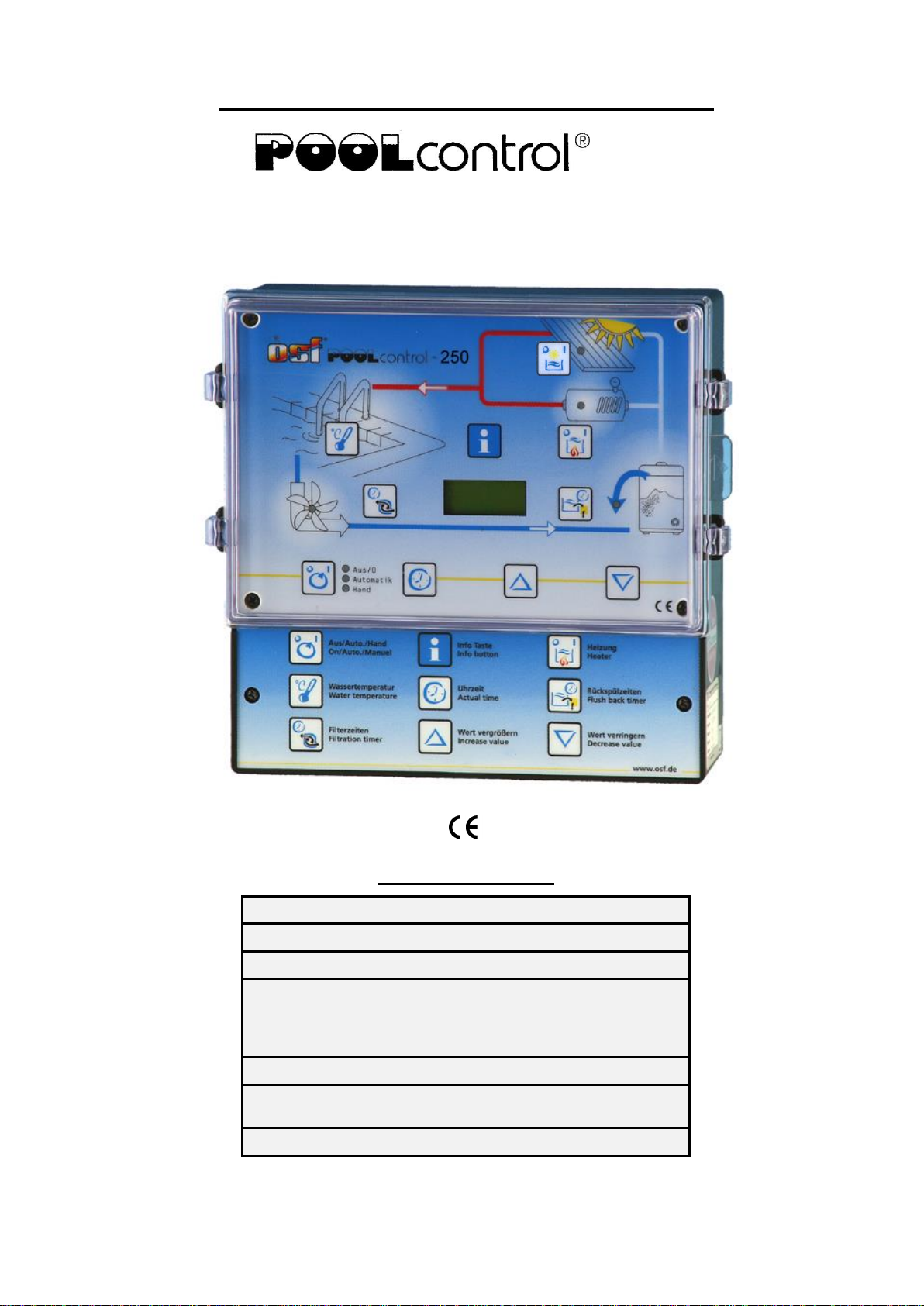
The PC-250 filter control unit enables
time-dependent switching on and off of a
400 V three-phase current pump or a 230
V alternating current filter pump in
accordance with a freely programmable
switching program.
Backflushing can be carried out both with
bar valves and with the
EUROTRONIK-10 backflushing control
system and 6-way valves.
heater of the swimming pool is controlled
by the electronic temperature regulation
system while the filter pump is running.
The heater is automatically switched off by
the internal interlock during filter pauses.
The required swimming pool water
temperature can be selected on the front
panel, or the heater can be switched off. A
floating contact (terminals 22 + 23) and a
voltage-carrying output (terminal U2) are
available for connecting the heater.
The microprocessor automatically
activates the solar temperature regulation
through the connection of a solar
temperature sensor (Art. No.
3100000030). Free solar energy will
therefore be given priority in heater the
swimming pool. The additional heater
(terminals U2 and N) will only be switched
on automatically if the solar unit is not
supplying any energy. The solar heater
and, simultaneously, the filter pump will
also start if solar energy is available
outside filter running times (timer off). The
solar temperature sensor is suitable for
operating solar absorbers through which
the swimming pool water flows directly.
This controller is not usable for other types
of solar collector.
Terminals for electronic level regulation
NR-12-TRS-2 (Art. No. 3030075020)
enable convenient automatic regulation of
the swimming pool water level. The filter
pump is also additionally protected against
damage which could be caused by filter
unit operation without water.
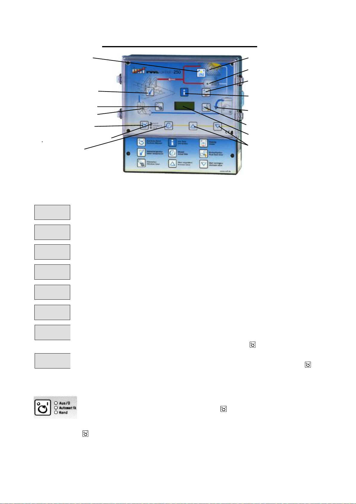
The INFO key on the front panel enables
reading out of various operating
parameters in addition to language
changeover.
Extra terminals enable the connection of
additional devices such as a dosing
system. Terminals 20 + 21 are floating,
and can therefore be used individually.
The relay contact between terminals 20
and 21 remains closed during the filter
periods, the relay contact is opened
outside these periods. This contact can be
loaded with a voltage of maximum 230 V
and a current of maximum 8 A.
The terminals for the coil earthing contact
enable the connection of a coil earthing
contact switch which is integrated in the
filter pump motor windings. If this contact
opens, for example due to excessive
motor winding warming, the filter pump will
be switched off automatically, and with it
the heater and dosing system. As soon as
the coil earthing contact closes once the
motor windings have cooled down, the
units will be started up again automatically.
Manual resetting is not necessary. The
terminals for the coil earthing contact are
provided with 230 V.
Operation of filter pump and heater is
displayed by indicator lamps in the front
panel, which means that checks can be
made at any time.
The filter pump is protected by an
electronic motor protection system (current
range infinitely variable up to 8A) against
overloading.

Front panel displays and controls:
solar button ON/OFF
adjust temperature
adjust switching times
control light filter pump
select operating mode
control lights operating mode
art
set time
adjust backflushing
control light solar heating
control light heating
heating ON/OFF
LCD
adjustment buttons
info Button
control light backflushing
LCD display
LCD display
23,4
14:46
°C
Normal operating display with current water temperature and time.
Auffang-
behälter
The filter pump is switched on by the NR-12-TRS-2 level regulation system.
6-Wege
Spülung
The filter pump is switched on by the EUROTRONIK-10 backflushing
control system.
Pumpe
gesperrt
The filter pump is switched off by the EUROTRONIK-10 or the NR-12-TRS-
2 level regulation system.
Rück-
spülen
The filter pump is switched on because backflushing is taking place using
the bar valve connected.
Klar-
spülen
The filter pump is switched on because rinsing is taking place using the bar
valve connected.
Motor-
schutz
The filter pump has been switched off by the electronic motor protection
system. Once the pump has cooled down and the cause of overloading has
been rectified, it can be switched on again using the key.
Phase
fehlt
The filter pump is switched off because current is not flowing in all 3 phases
of the 3-phase current network. It can be switched on again using the key
once the error has been rectified.
Selecting operating mode
The control system can be switched off or you can select between manual
and automatic operating mode using the key. Caution! This does not
mean that the control system has been switched to voltage-free! The
operating mode selected is displayed using the indicator lamps next to the
key.

PC-250 Filter control unit operating manual Page: 6 (24
Pump indicator lamp
This indicator lamp displays filter pump operation. You can see the pump
operating mode from the lamp colour:
Off: the filter pump is switched off
Green: the filter pump is in operation
Red: the pump has been temporarily switched off by the NR-12-TRS-2
level regulation system or the EUROTRONIK-10 backflushing system, the
motor protection has triggered or it was switched off by phase fields.
Heater indicator lamp
This indicator lamp displays heater operation. You can see the heater
operating mode from the lamp colour:
Off: the heater is off
Green: the heater is in operation
Red: the additional heater is blocked.
Use the key to block or release the heater. The solar heater is not
switched using this key.
Solar heater
If a solar sensor has been connected to the control system, this indicator
lamp is used to show the current operating status of the solar heater.
Backflushing process indicator lamp
This indicator lamp always illuminates if backflushing or rinsing using the
bar valve is taking place.
Selecting the temperature
Use the key to select the swimming pool water temperature.
1. Press the key the display shows
2. Use the and keys to set the required temperature between 0 °C and
40 °C.
3. Press the key again to save the required temperature. If no key is
pressed for more than 10 seconds during temperature setting, the last
temperature selected is saved automatically and the normal operating
display will be shown again.
Switching on frost protection mode
If you press the , and keys simultaneously, frost protection mode is
selected and the display shows
1. Use the and keys to switch frost protection mode on or off.
2. Press the key again to save the required operating mode . If frost
protection mode has been switched on, the display will show:
24,5
Wasser:
°C
aus
Frost.
utz mode
Frostsch

PC-250 Filter control unit operating manual Page: 7 (24
Setting the time
Use the key to set the current time:
1. Press the key the display shows
Sa 14:46
Uhrzeit
, the minute display
blinks.
2. You can now use the and keys to set the minutes.
3. Press the key the hour display blinks.
4. You can now use the and keys to set the hours.
5. Press the key the weekday display blinks.
6. You can now use the and keys to set the weekday.
Press the key again to save the time. If no key is pressed for more than
10 seconds during setting, the last time displayed is saved automatically
and the normal operating display will be shown again.
Programming the timer
Use the key to program the built-in timer, whereby the switch-on time and
the associated switch-off time must always be entered as pairs.
1. Press the key the display shows
-----
1.
if no switching time
has yet been programmed.
2. If you press one of the or keys, or if a switching time has already
been programmed, the display shows
0:00
0:00
1.
, the minute display of
the top time (switch-on time) blinks. Note: if you press the key, the
current time will be taken over.
3. You can now use the and keys to set the required switch-on time
minutes.
4. Press the key again the hours in the switch-on time blink
5. You can now use the and keys to set the required switch-on time
hours.
6. Press the key again the minutes in the switch-off time blink
7. You can now use the and keys to set the required switch-off time
minutes. Note: if you press the key, the current time can be taken
over, if you press the and keys simultaneously the switch-on time
set previously will be taken over.
8. Press the key again the hours in the switch-off time blink
9. You can now use the and keys to set the required switch-off time
hours.
10.Further switching times can now be programmed as in points 1-9.
11.Press the key again to save the switching time. If no key is pressed
for more than 10 seconds during setting, the last switching time
displayed is saved automatically and the normal operating display will
be shown again.
Delete rinsing time:
If switching times have already been programmed, you can use the key

PC-250 Filter control unit operating manual Page: 8 (24
to delete them.
1. Press the key as often as required until the switching time to be
deleted is displayed
10:00
16:00
3.
2. The switching time is deleted if you press the and keys
simultaneously.
Note:
If you press the key, the current time is taken over.
Programming backflushing
Use the key to control backflushing using the bar valve.
1. Once the key has been pressed the first time, you can use the and
keys to set the backflushing duration
10 Sek.
Rückspül
.
2. Once the key has been pressed the next time, you can use the and
keys to set the rinsing duration
10 Sek.
Klarspül
.
3. Once the key has been pressed again, you can set the time of the
rinsing process
Mo 16:00
1. Start
.
In the first stage, the and keys are used to set the minutes.
If you press the key, the current time is taken over.
4. Press the key again the hours in the switch-on time blink
You can now use the and keys to set the hours.
5. Press the key again the switch-on time weekday blinks.
You can now use the and keys to set the weekday.
6. Further start times can be programmed in the same manner as
described in points 1 to 5.
Deleting switching times:
If you press the and keys simultaneously, the rinsing time shown in the
display will be deleted.
Note:
If you press the key, the current time is taken over.
Start backflushing process manually
If the backflushing key is pressed for 3 seconds without interruption, the
backflushing process will start. Backflushing will not start unless a
backflushing duration has been entered.
Info key
If you press the INFO key, the program version number will be displayed
:
If the info key is pressed several times successively, the following information
can be called up.
1) Language
PC250
ver.1.xx

PC-250 Filter control unit operating manual Page: 9 (24
The current language is displayed. If you press the and keys, you can
switch between the German and English languages. The language
displayed will be saved automatically.
2) Solar temperature
3) Water temperature
4) Filter pump operating status
5) Additional heater operating status
6) Solar heater operating status
7) Filter pump operating hours counter
8) Additional heater operating hours counter
9) Solar heater operating hours counter
10) Motor protection
The trigger current set for the motor protection system is visible in the
display.
2 facilities are available for setting the motor protection system.
a) The current motor current is accepted and saved if the filter pump is
running and the and keys are pressed simultaneously. (The starting
current delay factor is automatically declared.)
b) If you press the or keys, the filter pump current consumption
can be set manually. The current displayed will be saved automatically.
11) Quit info mode
To quit the information mode, press the Info key for 3 seconds without
interruption.
If the Info key is not pressed for a longer period, the device switches back
to the normal operating display automatically.
Installation
The controller must be protected against moisture in accordance with its protection class,
and the fixed to a plain, fireproof support with suitable loading capacity and must be out of
the reach of children. You should avoid direct sunlight, UV radiation and formation of
condensate due to temperature variations. The device must be powered via a multi-pole
main switch with a contact opening width of at least 3mm and a residual current circuit
breaker with IFN30mA . The device must be isolated before opening the housing.
Electrical power supply
Electrical power supply connections, in addition to alignment and service work, may only be
carried out by approved electricians. The attached circuit diagrams and all applicable safety
regulations must be observed. All conductive components must be included in the
equipotential bonding.
NTC
sensor
Water
temp.
PC-250
Filter pump
400V
max. 8A
Solar
Actuator
Aktive
NTC
sensor
Solar
temp.
Dosing system
floating
max. 8A
L1
L2
L3
N
Mains
3 / N / PE
400V 50Hz
30
31
32
33
U1
W1
V1
WSK
U2
U3
U4
U5
U6
2
3
4
5
11
12
13
14
20
21
22
23
Heater floating
max. 8A
M
3~
Winding
protection
contact
N
N
N
N
EUROTRONIK-
10
Level regulation
NR-12-TRS-2
Heater 230V 2A
Backflushing 230V 2A
Rinsing230V 2A
*Remove bridge if
connecting NR-12-TRS-2 or
Eurotronik-10
!
*
*
All components must be included in the equipotential bonding!

PC-250 Filter control unit operating manual Page: 10 (24
Mains connection when using 400V 3-phase pump:
Pool-Control-250
Wicklungs-
3M
W1V1U1L1 L3L2 NWSK
FI-Schalter schutz-
max. B16A
Vorsicherungen
400V max. 8A
Filterpumpe
Netz 3/N/
400/230V 50Hz
25A/0,03A kontakt
The bridge fitted in the works between the terminals labelled WSK must be removed if a
pump with coil earthing contact is connected. If no such connection is made, it must remain
fitted. These terminals carry mains voltage!
Mains connection when using 230 V AC pump:
Pool-Control-250
Wicklungs-
1
M
W1V1U1L3L2L1 NWSK
schutz-
230V max. 8A
Filterpumpe
max. B16A
Vorsicherung
FI-Schalter
Netz 1/N/
230V 50Hz
25A/0,03A
N
kontakt
The bridge fitted in the works between the terminals labelled WSK must be removed if a
pump with coil earthing contact is connected. If no such connection is made, it must remain
fitted. These terminals carry mains voltage!
The motor current must be fed using all 3 switching contacts in the filter control unit so that
the electronic motor protection works correctly (terminals L2 and L3 in addition to U1 and
V1 bridged, pump connected to W1).
Heater connection
Floating contact (e.g. for
boiler control)
230V heater (e.g. circulation
pump)
Solar heater
PC-250
max. 8A
22
23
Heizung
potentialfrei
PC250
max. 2A
U2
Heizung 230V
N
PC-250
U5
N
6
2
3
U6
Stellantrieb 230V
Solar-

PC-250 Filter control unit operating manual Page: 11 (24
The floating relay contact between terminals 22 and 23 can be loaded with a voltage of
maximum 230 V and a current of maximum 8 A.
If the heater requires 230 V, it can be connected to terminal U2. Terminals are also
available for the heater N connection.
A 230 V solar actuating drive can be connected to terminals U5 and U6 for operating
the solar heater. When operating solar heater, terminal U5 carries the mains voltage and
terminal U6 is voltage-free. If the solar heater is not being operated, terminal U5 remains
voltage-free and terminal U6 carries the mains voltage. These contacts may the loaded
with a maximum 230 V/1.5A.
Level regulation and backflushing control
Filtersteuerung PC-30
NR-12-TRS-2
steuerung
Auffangbehälter-
11
12
13
14
11
12
13
14
U3
N
Rückspülventil
230V
max.2A
EUROTRONIK-10
2
3
4
5
2
3
4
5
Rückspülsteuerung
U4
N
Klarspülventil
230V
max.2A
A 230 V bar valve for backflushing can be connected to terminals U3 and N.
A 230 V bar valve for rinsing can be connected to terminals U4 and N.
Both valves will be controlled by the internal backflushing controller.
Heater and dosing systems are blocked during the backflushing and rinsing processes.
Either bar valves or a EUROTRONIK-10 can be used for backflushing or rinsing.
The bridge fitted in the works between terminals 13 and 14 must be removed if level
regulation system NR-12-TRS-2 is connected. The bridge can remain between these
terminals if no level regulation system is connected. Terminals 11 and 12 remain unused in
this case. These terminals carry mains voltage!
The bridge fitted in the works between terminals 3and 5must be removed if a
EUROTRONIK-10 system is connected. The bridge can remain between these terminals if
no EUROTRONIK-10 system is connected. Terminals 2and 4remain unused in this case.
These terminals carry mains voltage!
Opening any of the contacts between terminals 13 and 14 or 3 and 5 causes filter pump,
dosing systems and heater to be turned off immediately.
Closing any of the contacts between terminals 2 and 4 or 11 and 12 causes forced
switching on of the filter pump, whereas heater and dosing systems are switched off.

PC-250 Filter control unit operating manual Page: 12 (24
Dosing system connection
PC-250
20
21
Dosiertechnik
(potentialfrei)
max. 230V / 8A
There is a floating relay contact between terminals 20
and 21. This can, for example, be used for activation of
the dosing system (the contact remains closed during
filter operation).
This contact can be loaded with a maximum of 230 V/8A.
Temperature sensor connection
Schwimmbad
Temperaturfühler
30
31
Fühler
Solar-
32
33
Filtersteuerung PC-250
-Tauchhülse
The swimming pool temperature sensor is connected to terminals 30 and 31. The
temperature sensor is supplied with a cable length of 1.5 m as standard. If required, this
can be lengthened to maximum 20 m (cross-section minimum 0.5 mm²) with a 2-core
cable. You should avoid routing the sensor cable near power cables to prevent possible
interference.
Since precise temperature control can only be achieved with good heat transfer between
temperature sensor and swimming pool water, an immersed sleeve R ½" (Art. No.
3200200003) should be built into the piping system. The sensor polarity is as required.
A solar temperature sensor (Art. No. 3100000030) can be additionally connected to
terminals 32 and 33. The temperature sensor is supplied with a cable length of 20 m as
standard. If required, this can be lengthened to maximum 50 m (cross-section minimum
0.5mm²) with a 2-core cable. You should avoid routing the sensor cable near power cables
to prevent possible interference. The solar temperature sensor should be connected at the
solar collector output and must have good heat contact to the returning water flow. The
temperature at the temperature sensor installation site may not exceed 80 °C.
Setting motor protection
Please see the Info key information in menu command 10.
Starting the backflushing process
If the backflushing key is pressed for 3 seconds without interruption, the backflushing
process will start. Backflushing will not start unless a backflushing duration has been
entered.
Submerged sleeve

PC-250 Filter control unit operating manual Page: 13 (24
Balancing the temperature controller
The electronic temperature regulator and the temperature
centre are balanced with one another in the works. If one of
the sensors is replaced, or if a sensor cable is extended, a
new balance must be carried out if necessary using the
potentiometers in the controller. Turning the water
temperature sensor potentiometer clockwise causes an
increase in the water temperature displayed. If the solar
sensor potentiometer is turned clockwise, a higher collector
temperature is displayed. Since the solar temperature
regulation only works correctly with precisely balanced
sensors, this balance should only be carried out by a trained
service technician.
Temperature sensor resistance
Both temperature sensors have the resistance
values listed to the right.
Fuses
The electronic control system is protected by a 0.25A fine-wire
fuse on the PCB in the inside of the device. The short-circuit
protection for the filter pump must be provided by a backup
fuse of maximum 16A on site.
Service terminal
An osf service terminal (Art. No. 3010000900) can be
connected to this control system for optimum control system
settings for a wide range of swimming pool equipment and for
assisting in initial startup and fault diagnosis. The socket for
this is located on the rear of the top PCB inside the device.
Before opening the housing and plugging in the service
terminal, you must ensure that the control system has
been isolated from the mains! Once the control system has
been switched on, the service terminal display shows the first
4 lines of the diagnosis text, e.g.:
Filterbetrieb
Temp. erreicht
Wasser: 23,0°
Solar: 38,4°
Betriebsart der Filteranlage
Betriebsart der Heizung
gemessene Wassertemperatur
gemessene Kollektortemperatur
Temperature Resistance
20°C 5800 Ohm
25°C 4600 Ohm
30°C 3700 Ohm

PC-250 Filter control unit operating manual Page: 14 (24
Further lines can be called up using the and keys. Values in the top line can be
changed by pressing the key if necessary.
Filter unit operating mode
This line displays the current filter unit operating mode.
The following displays are possible:
Control system off
Use the key to switch the control system off.
Filter unit off
The filter unit is switched off.
Filter operation
The filter unit is switched on using the timer or the key
on the front cover.
Run-on time
The filter pump continues running when the heater is
switched off.
Forced switching
The filter pump is either switched on by the
EUROTRONIK-10 backflushing controller or the NR-12-
TRS-2 level regulation system.
Priority circuit
Outside the set filter times, the filter pump is switched on
by the temperature regulation system because this works
in the priority circuit.
Pump blocked
The filter pump is switched off temporarily by the
EUROTRONIK-10 or the NR-12-TRS-2 level regulation
system.
Backflushing
The filter pump is switched on because backflushing is
taking place using the bar valve.
Rinsing
The filter pump is switched on because rinsing is taking
place using the bar valve.
Frost protection
mode
The filter pump is in frost protection operating mode.
Heater operating mode
This line displays the current temperature regulation operating mode.
The following displays are possible:
Controller off
Use the key to switch the heater off.
Add. heater off
The heater is switched off outside the filter times.
Heater blocked
The heater is switched off because the EUROTRONIK forced
switching has occurred.
Temp. reached
The heater is switched off because the set temperature has
been reached.
Add. heater on
The heater is switched on because the water temperature is
below the set temperature.
Solar heater on
The solar heater is switched on because the water
temperature is below the set temperature and the collector is
warmer than the swimming pool water.
Frost hazard
The heater is switched on in frost protection operating mode.

Water temperature
The current water temperature is
displayed in this line. If the display
does not agree with the actual
temperature, it can be readjusted
using the adjuster on the printed
circuit board (see temperature
regulation section). Turn the adjuster
in a clockwise direction to increase
the displayed value. "Sensor break"
will be displayed if the temperature
sensor is defective. Caution: If both
temperature sensors are at the
same temperature, the solar
sensor must never display a
higher value than the water
temperature sensor otherwise the
solar heater will not switch off.
Solar temperature
The current collector temperature is
displayed in this line. If the display
does not agree with the actual
temperature, it can be readjusted
using the adjuster on the printed
circuit board (see temperature
regulation section). Turn the adjuster
in a clockwise direction to increase
the displayed value. "-----" will be
displayed if the temperature sensor is
defective. Caution: If both
temperature sensors are at the
same temperature, the solar
sensor must never display a
higher value than the water
temperature sensor otherwise the
solar heater will not switch off.
Additional heater
The additional heater operating status is displayed in this line.
Solar
The solar heater temperature is displayed in this line.
Water
The temperature at the water temperature sensor is displayed in this line.
Set temperature
The set temperature is displayed in this line, and this is set using the key in the
front cover.
Current
The filter pump current consumption for each phase is displayed in this line.
Motor protection
The triggering current for the motor protection is displayed in this line.
Solar difference
This line displays how much warmer the solar collector needs to be than the
swimming pool water before the solar heater is switched on.
Solar-
differenz
Kollektortemperatur
Wassertemperatur
Solarheizung aus
Solarh. ein
Solarheizung aus
Solarh. ein
Solar-
differenz
This value can be adjusted to meet the requirements of the relevant solar equipment
if it is displayed in the top line of the service terminal.

PC-250 Filter control unit operating manual Page: 16 (24
1. Once the key has been pressed, the filter unit is switched off and the display
shows the following:
Solardiff.: °
Differenztemp.
zwischen Wasser
und Kollektor
3
2. Now use the and keys to change the temperature difference. The smallest
adjustable value is 0.5°, the largest 10°.
3. If you press the key again, the normal diagnosis display appears and the filter
unit continues to operate. The adjusted value will be saved automatically.
A temperature difference of 3° is set at the works.
Solar additional temperature
This line displays by how much the swimming pool set temperature may be
exceeded during solar heating in order to make optimal use of solar energy during
the day. This value can be adjusted to meet the requirements of the relevant
swimming pool if it is displayed in the top line of the service terminal.
1. Once the key has been pressed, the filter unit is switched off and the display
shows the following:
Solar-Zus.: °
Überheizen
des Wassers
bei Solarbetrieb
5,0
2. Now use the and keys to change the temperature difference. The smallest
adjustable value is 0°, the largest 15°.
3. If you press the key again, the normal diagnosis display appears and the filter
unit continues to operate. The adjusted value will be saved automatically.
A temperature difference of 5° is set at the works.
Limit temperature
This line displays at which maximum temperature the solar heater is to be switched
off automatically for safety reasons independent of the nominal value set. This value
can be adjusted to meet the requirements of the relevant swimming pool if it is
displayed in the top line of the service terminal.
1. Once the key has been pressed, the filter unit is switched off and the display
shows the following:
Grenztemp.: °
Maximal mögliche
Wassertemperatur
bei Solarbetrieb
40,0
2. Now use the and keys to change the limit temperature. The smallest
adjustable value is 30°, the largest 50°.
3. If you press the key again, the normal diagnosis display appears and the filter
unit continues to operate. The adjusted value will be saved automatically.
A temperature difference of 40° is set at the works. This limit temperature influences
the solar heater only.
Additional heater minimum time (hysteresis)
This line displays the minimum switching on or off durations for the additional heater
by the temperature regulation to avoid too short switching periods. This value can be

PC-250 Filter control unit operating manual Page: 17 (24
adjusted to meet the requirements of the relevant heater equipment if it is displayed
in the top line:
1. Once the key has been pressed, the filter unit is switched off and the display
shows the following:
Min.Heizen: s
Minimale
Einschaltzeit
der Heizung
120
2. Use the and keys to change the minimum time in stages of 10s. The smallest
adjustable value is 10s, the largest 1800s
3. If you press the key again, the normal diagnosis display appears and the filter
unit continues to operate. The adjusted value will be saved automatically.
The time set here only influences the temperature regulator behaviour. If the filter
pump is switched off, the additional heater is switched off without delays irrespective
of the holding time set. A minimum duration of 2 minutes is set at the works.
Solar heater minimum time (hysteresis)
This line displays the minimum switching on or off durations for the solar heater by
the temperature regulation to avoid too short switching periods. This value can be
adjusted to meet the requirements of the relevant solar equipment if it is displayed in
the top line:
1. Once the key has been pressed, the filter unit is switched off and the display
shows the following:
Min. Solar: s
Minimale
Einschaltzeit
der Solarheizung
120
2. Use the and keys to change the minimum time in stages of 10s. The smallest
adjustable value is 10s, the largest 1800s
3. If you press the key again, the normal diagnosis display appears and the filter
unit continues to operate. The adjusted value will be saved automatically.
The time set here only influences the temperature regulator behaviour. If the filter
pump is switched off, the heater is switched off without delays irrespective of the
holding time set. A minimum duration of 2 minutes is set at the works.
Filter pump run-on time
This line displays for how long the filter pump runs on after the additional heater has
been switched off. This value can be adjusted to meet the requirements of the
relevant filter unit if it is displayed in the top line:
1. Once the key has been pressed, the filter unit is switched off and the display
shows the following:
Nachlauf: s
Nachlaufzeit der
Filterpumpe nach
d. Zusatzheizung
10
2. Now use the and keys to change the warm-up time. The smallest adjustable
value is 0s, the largest 1800s
3. If you press the key again, the normal diagnosis display appears and the filter
unit continues to operate. The adjusted value will be saved automatically.
Filter pump run-on is switched off at the works (run-on time = 0).

PC-250 Filter control unit operating manual Page: 18 (24
Heater priority circuit
This line displays whether the temperature regulation system has priority over the
filter time settings. Using the priority circuit, the filter pump can be switched on by the
temperature regulation system even outside the set filter times. The temperature
regulation only works during the filter times without the priority circuit.
The following displays are possible:
Priority OFF
The additional heater only works during the filter times.
Priority ON
The temperature regulation also works outside the filter
times. If the water temperature falls below the set
temperature, the filter pump and the additional heater are
switched on automatically .
If the priority circuit is displayed in the top line of the service terminal it can be
switched on or off.
1. Once the key has been pressed, the filter unit is switched off and the display
shows the following:
Vorrang: AUS
Vorrangschaltung
der Zusatz-
heizung
2. Use the key to switch the priority circuit on, and the key to switch it off.
3. If you press the key again, the normal diagnosis display appears and the filter
unit continues to operate.
The additional heater priority is switched off at the works.
Solar heater priority circuit
This line displays whether the solar heater has priority over the filter time settings.
Using the priority circuit, the filter pump can be switched on by the temperature
regulation system even outside the set filter times. The temperature regulation only
works during the filter times without the priority circuit.
The following displays are possible:
Prior.Solar OFF
The solar heater only works during the filter times.
Prior. Solar ON
The solar heater also works outside the filter times. The
filter pump and solar heater are switched on automatically
in sunshine.
If the priority circuit is displayed in the top line of the service terminal it can be
switched on or off.
1. Once the key has been pressed, the filter unit is switched off and the display
shows the following:
Vorr. Solar EIN
Vorrangschaltung
der Solar-
heizung
2. Use the key to switch the priority circuit on, and the key to switch it off.
3. If you press the key again, the normal diagnosis display appears and the filter
unit continues to operate.
The solar heater priority is switched on at the works.

PC-250 Filter control unit operating manual Page: 19 (24
The following lines are used for manual activation of the output relay.
Frost protection
This line displays the current frost protection function switch-on temperature. This
value can be adjusted to meet the requirements of the relevant filter unit if it is
displayed in the top line:
1. Once the key has been pressed, the filter unit is switched off and the display
shows the following:
Frostsch.:
Einschalttemp.
des Frost-
schutzes
°C
2. Now use the and keys to change the temperature. The smallest adjustable
value is -3°, the largest 5°.
3. If you press the key again, the normal diagnosis display appears and the filter
unit continues to operate. The adjusted value will be saved automatically.
4. A switch-on temperature of 0° is set at the works.
Pump time
This line displays the total operating hours for the filter pump.
heater time
This line displays the total operating hours for the additional heater.
Solar time
This line displays the total operating hours for the solar heater.
Motor defect
This line displays the number of "motor protection" error messages.
Phase fields
This line displays the number of "phase fields" error messages.
Int. backflushing (intern)
This line displays how often a backflushing process has been started by bar valves.
Ext. Backflushing (extern)
This line displays how often a backflushing process has been started by the
EUROTRONIK-10.
The following lines enable the service technician to carry out an examination of the input
signals and filter control unit output relay.
Forced switch-on of NR-12-TRS-2
This line displays whether the NR-12-TRS-2 level regulation system is subject to
forced switch-on.
The following displays are possible:
Forced switch-
onOFF
No forced switch-on, or terminals 11 and 12 not
connected.

PC-250 Filter control unit operating manual Page: 20 (24
Forced switch-on ON
Forced switch-on requested, or terminals 11 and 12
connected.
EUROTRONIK backflushing signal
This line displays whether the EUROTRONIK-10 switches the filter pump on during
backflushing or rinsing.
The following displays are possible:
EUROTRONIK OFF
no switch-on command from EUROTRONIK
EUROTRONIK ON
The EUROTRONIK has switched the filter pump on
EUROTRONIK OFF
The EUROTRONIK has switched the filter pump off
Interlocking
This line displays whether the filter unit has been switched off either by the
EUROTRONIK, NR-12-TRS-2 or the coil earthing contact.
The following displays are possible:
Interlock OFF
The pump is switched off (one of the contacts is open).
Interlock ON
Pump operation has been enabled (all interlock contacts
are closed)
Filter pump
When the filter pump operating status is displayed in the top line of the service
terminal, the pump can be switched on or off manually.
1. Once the key has been pressed, the filter unit is switched off and the the
following is displayed:
Filterpumpe: AUS
Pumpe kann von
Hand geschaltet
werden!
2. Use the key to switch the filter pump on, and the key to switch it off. Caution!
the electronic motor protection does not function in this operating mode!
3. If you press the key again, the normal diagnosis display appears and the filter
unit continues to operate.
Solar operation
When the solar heater operating status is displayed in the top line of the service
terminal, it can be switched on or off manually.
1. Once the key has been pressed, the filter unit is switched off and the the
following is displayed:
Solaranlage
HANDBETRIEB
Stellantrieb: AUS
Pumpe: AUS
2. Use the key to switch the solar heater on, and the key to switch it off. When
the solar heater is switched on, the following is displayed:
Solaranlage
HANDBETRIEB
Stellantrieb: EIN
Pumpe: AUS
Table of contents
Other OSF Control Unit manuals
Popular Control Unit manuals by other brands

National Instruments
National Instruments C Series Getting started guide

Buderus
Buderus Logamatic 4323 operating instructions

RADEMACHER
RADEMACHER ReWiSo Installation and operating instructions

Honeywell
Honeywell V5197A1011 Product data

Silicon Laboratories
Silicon Laboratories Si8410 manual

Woodward
Woodward Large Electric Sonic Valve II Installation and operation manual