LEXPERT EMPHASY
7
5. ELECTRICAL CONNECTION
Connection to the electricity mains must be carried out by a qualified electrical installer.
This luminaire is designed for operating at a nominal voltage of 100 V - 240 V. It is fitted with a power supply cable (18 AWG yellow/green, brown and
blue cables). Check that the mains frequency and voltage correspond to those for which the luminaire is designed.
For your own safety, make sure the earth wire (yellow-green) is ALWA S connected to earth.
The power requirement is as following:
1. Turn the main power switch off first
2. Connect the conductors in the power cable to the distribution circuit as follows:
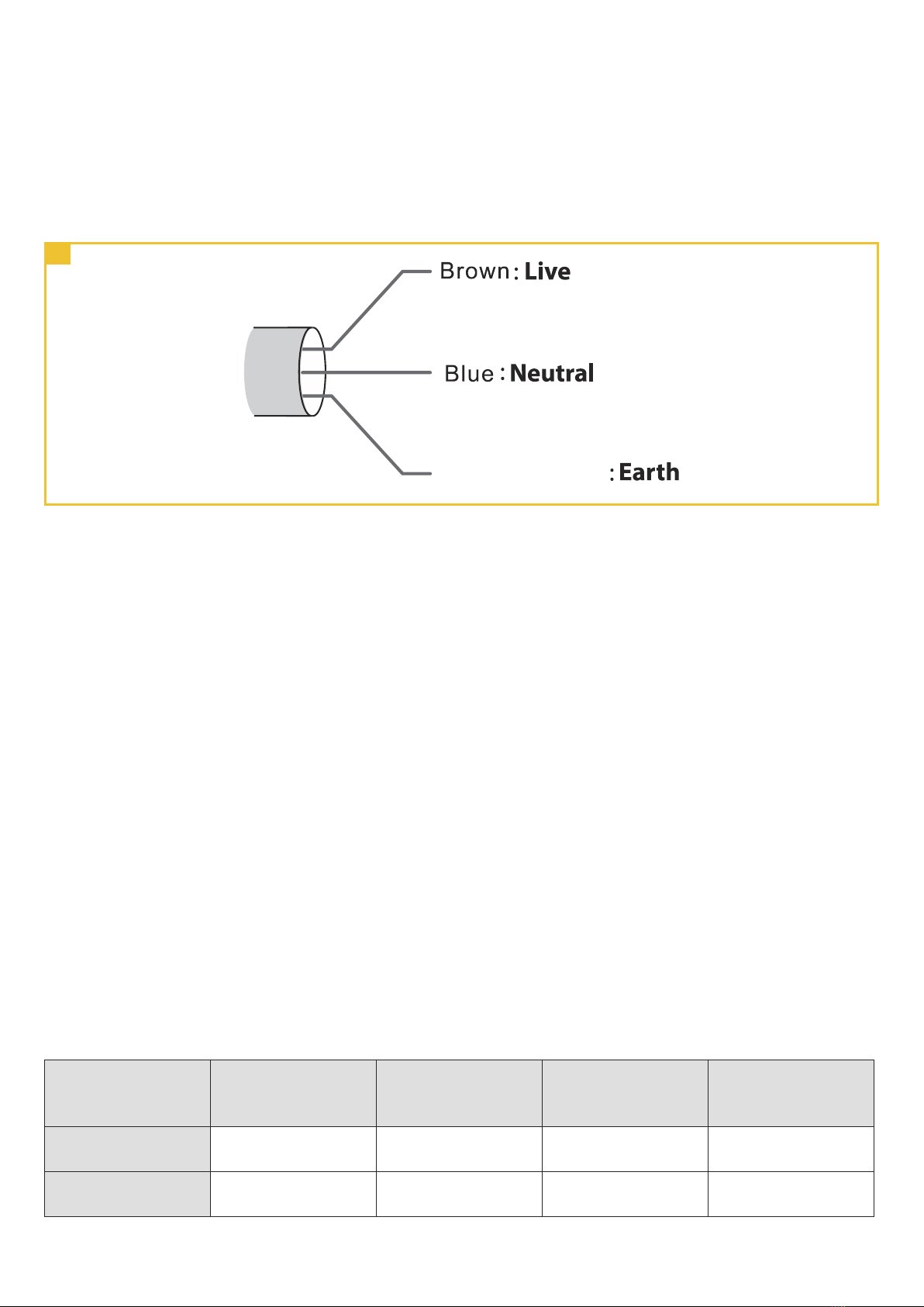
Connect the brown wire to live (one phase).
Connect the blue wire to neutral.
Connect the yellow/green wire to ground (earth).
3. Check that all installation work is completed and carry out appropriate tests and safety checks before applying power.
Important Remark
Power supply cables and other connections are essential for your equipment and contribute greatly to a safe and trouble-free operation.
1. Always hold the plug when disconnecting a cable, never pull the cable.
2. ever use cables or connections in bad condition, check them before installation and periodically thereafter.
3. ever tie power supply and data cables together.
5
Power cord colors - Fig. 5
6. DMX CONNECTION
Connect a female XLR5 cable into the luminaire’s DMX In input connector.
To send DMX 512 to another luminaire, connect a male XLR5 cable into the luminaire’s DMX Out connector.
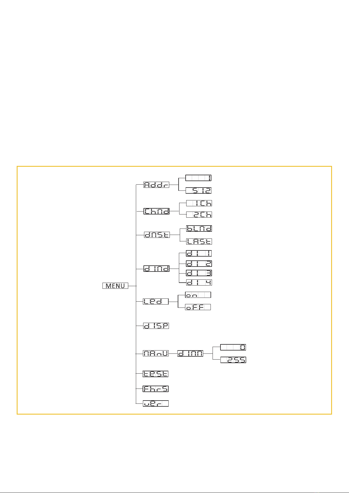
To control the units with a DMX 512 controller, you will need to set DMX address from 1 to 512 so that the units can receive DMX signal.
Press the ME U button up to when the DMX Address is showing on the display. Pressing the E TER button and the display will blink. Use the DOW /UP
button to change the DMX512 address. Once the address has been selected, press the E TER button to setup, to go back to the functions without any
change press the ME U button again. Hold and press the ME U button about one second or wait for one minute to exit the menu mode.
Please refer to the following diagram to address your DMX512 channel for the first 4 units:
Channel mode Unit 1
Address
Unit 2
Address
Unit 3
Address
Unit 4
Address
1 channels 1 2 3 4
2 channels 1 3 5 7