OSS EB3450 User manual

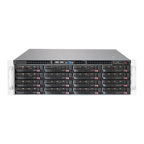
ExpressBox 3450
5 PCIe (3.0 x16) Slot Expansion Unit
5 Slot Gen 3 Expansion Chassis User Manual
SKU: EB3450
www.onestopsystems.com

One Stop Systems
EB3450 | 2
Table of Contents
Preface............................................................................................................................................................................................. 5
Advisories .............................................................................................................................................................................................. 5
Safety Instructions ................................................................................................................................................................................ 6
1 Introduction............................................................................................................................................................................... 8
1.1 EB3450 .................................................................................................................................................................................... 8
1.2 EB3450 Features .................................................................................................................................................................... 8
1.3 EB3450 Technical Specification.......................................................................................................................................... 9
1.4 Parts List ................................................................................................................................................................................ 10
1.5 Components of EB3450 unit.............................................................................................................................................. 11
1.6 Pre-Installation Information ............................................................................................................................................... 13
1.7 Tools Required for Installation ........................................................................................................................................... 13
2 Hardware Installation ............................................................................................................................................................. 14
2.1 Installation-Procedures Overview .................................................................................................................................... 15
2.2 Open Enclosure .................................................................................................................................................................. 16
2.3 Install Expansion Interface Card ...................................................................................................................................... 16
2.4 Install Host Interface Card................................................................................................................................................. 17
2.4.1 Low Profile Bracket Installation............................................................................................................................... 17
2.5 Connect Link Cables ........................................................................................................................................................ 20
2.5.1 Connect cables to expansion unit........................................................................................................................ 21
2.5.2 Connect cables to computer / server.................................................................................................................. 21
2.6. Cable Configurations ........................................................................................................................................................ 22
2.6.1 Cable configuration for EB3450 ............................................................................................................................. 24
2.7 Install GPU / PCIe cards..................................................................................................................................................... 25
2.7.1 PCIe card Memory Requirements ......................................................................................................................... 26
2.7.2 PCIe card Power Requirements............................................................................................................................. 27
2.7.3 K80 Installation .......................................................................................................................................................... 27
2.8 Connect Power Cord / Cable.......................................................................................................................................... 29
2.9 Connecting to Electrical Outlets...................................................................................................................................... 30
2.9.1 Use two separate circuit lines................................................................................................................................. 31
2.9.2 Don’t use multiple electrical outlets on one circuit line..................................................................................... 31
2.10 Power on EB3450 ........................................................................................................................................................... 33
2.11 Power on Computer ..................................................................................................................................................... 34
2.12 Hardware Check........................................................................................................................................................... 34
2.12.1 Check and verify Expansion and Host Cards LEDs ........................................................................................ 34
2.12.2 Check Front Panel Status................................................................................................................................... 35
2.12.3 Check Backplane LEDs ...................................................................................................................................... 35
2.13 Verify Installation............................................................................................................................................................ 36

One Stop Systems
EB3450 | 3
2.13.1 Windows ............................................................................................................................................................... 36
2.13.2 Slot# Assignment and Device# Designation.................................................................................................. 37
2.13.3 Linux....................................................................................................................................................................... 40
2.13.4 Slot# and port reference ................................................................................................................................... 42
3 Additional Technical Information.......................................................................................................................................... 46
3.1 EB3450 Configuration......................................................................................................................................................... 46
3.2 Backplane and LEDs .......................................................................................................................................................... 47
3.3 Card Slot Link LEDs.............................................................................................................................................................. 49
3.4 Interface Card and LEDs................................................................................................................................................... 50
3.5 Display Functions of Interface card LEDs........................................................................................................................ 51
3.6 Reset & Power Status LEDs ................................................................................................................................................ 52
3.7 Cooling Fans........................................................................................................................................................................ 53
3.7.1 How to Replace Fans.............................................................................................................................................. 53
3.7.2 Fan Specs .................................................................................................................................................................. 55
3.8 Power Supply unit ............................................................................................................................................................... 56
3.8.1 Power Supply Specifications................................................................................................................................... 56
3.8.2 AC Input..................................................................................................................................................................... 56
3.8.3 DC Output ................................................................................................................................................................. 57
3.8.4 DC Output Load Distributions................................................................................................................................. 57
3.8.5 Output Signals (Redundant System) ..................................................................................................................... 58
3.8.6 Environmental ........................................................................................................................................................... 59
3.9 EB3450 Power Consumption ............................................................................................................................................. 59
3.9.1 Power consumption breakdown per hardware ................................................................................................. 59
4 Express I/O Manager ............................................................................................................................................................. 60
4.1 Express I/O Management module................................................................................................................................... 60
4.2 Web Server and SNMP Features....................................................................................................................................... 60
4.3 Web Access and SNMP Configuration ........................................................................................................................... 60
4.3.1 Supported Internet Browser .................................................................................................................................... 61
4.4 To Access Express IO Manager / SNMP........................................................................................................................... 61
4.4.1 Connect Ethernet Cable ........................................................................................................................................ 61
4.4.2 Configure Network Setting...................................................................................................................................... 61
4.4.3 How to configure your network setting in Windows OS ..................................................................................... 62
4.4.4 How to configure your network setting in Linux / Ubuntu .................................................................................. 63
4.4.5 Launch Internet Browser.......................................................................................................................................... 64
4.4.6 Authentication Log-in.............................................................................................................................................. 64
4.4.7 Default Home Webpage ........................................................................................................................................ 65
4.5 Express IO Manager Webpage........................................................................................................................................ 65
4.5.1 HOME TAB .................................................................................................................................................................. 66
4.5.2 ADMINISTRATOR TAB ................................................................................................................................................ 66

One Stop Systems
EB3450 | 4
4.5.3 SNMP SETTINGS.......................................................................................................................................................... 66
4.5.4 ALARM SETTINGS ....................................................................................................................................................... 67
4.5.5 NETWORK ................................................................................................................................................................... 67
4.5.6 REMOTE MANAGEMENT........................................................................................................................................... 68
4.5.7 How to remote Turn ON and Off the chassis ....................................................................................................... 69
4.5.8 PCIe INFO................................................................................................................................................................... 69
4.5.9 Fan Control................................................................................................................................................................ 70
4.5.10 Fan Configuration ............................................................................................................................................... 71
4.6 Reset to Factory Default Values....................................................................................................................................... 71
4.6.1 How to reset the chassis to factory default parameters / values..................................................................... 72
4.7 How to Update the SNMP / NetBurner on Windows OS............................................................................................... 72
4.8 To Check and verify if the update................................................................................................................................... 75
4.9 Configure your SNMP Agent............................................................................................................................................. 76
4.10 Retrieving the MIB File................................................................................................................................................... 76
4.11 Accessing the various SNMP functions....................................................................................................................... 77
4.12 NetBurner Module ......................................................................................................................................................... 77
4.12.1 Replacing the NetBurner.................................................................................................................................... 77
4.12.2 NetBurner Installation.......................................................................................................................................... 80
4.12.3 Replacing the Interface Board ......................................................................................................................... 81
4.12.4 Interface Board Installation ............................................................................................................................... 82
5 Troubleshooting ........................................................................................................................................................................ 83
5.1 Locate the Problem ........................................................................................................................................................... 83
5.2 Computer Hangs During Power Up ................................................................................................................................. 83
5.3 Computer Doesn’t Detect Expansion Chassis ............................................................................................................... 83
5.4 Add-in card doesn’t work ................................................................................................................................................. 84
5.5 Windows Error Codes ......................................................................................................................................................... 84
6 Chassis Maintenance............................................................................................................................................................... 85
6.1 General Chassis Cleaning................................................................................................................................................. 85
6.2 Cleaning the Cooling fans................................................................................................................................................ 86
7 Frequently Asked Questions (FAQ) ......................................................................................................................................... 88
8 How to Get More Help.............................................................................................................................................................. 90
8.1 Contacting Technical Support......................................................................................................................................... 90
8.2 Returning Merchandise to OSS......................................................................................................................................... 90
Appendix A Compliance......................................................................................................................................................... 91

One Stop Systems
EB3450 | 5
Preface
Advisories
Five types of advisories are used throughout this manual to provide helpful information, or to alert you to the potential for hardware damage
or personal injury.
NOTE
Used to amplify or explain a comment related to procedural steps or text.
IMPORTANT
Used to indicate an important piece of information or special “tip” to help you
CAUTION
Used to indicate and prevent the following procedure or step from causing damage to the equipment.
WARNING
Used to indicate and prevent the following step from causing injury.
DANGER or STOP
Used to indicate and prevent the following step from causing serious injury or significant data loss
Disclaimer: We have attempted to identify most situations that may pose a danger, warning, or caution condition in this manual. However, OSS
does not claim to have covered all situations that might require the use of a Caution, Warning, or Danger indicator.

One Stop Systems
EB3450 | 6
Safety Instructions
Always use caution when servicing any electrical component. Before handling the OSS Expansion chassis, read the following instructions and
safety guidelines to prevent damage to the product and to ensure your own personal safety. Refer to the “Advisories” section for advisory
conventions used in this manual, including the distinction between Danger, Warning, Caution, Important, and Note.
Always use caution when handling/operating the computer. Only qualified, experienced, authorized electronics personnel should access the
interior of the computer and expansion chassis.
WARNING
Never modify or remove the radio frequency interference shielding from your workstation or expansion unit. To do so may
cause your installation to produce emissions that could interfere with other electronic equipment in the area of your
system.
When Working Inside a Computer
Before taking covers off a computer, perform the following steps:
1. Turn off the computer and any peripheral devices.
2. Disconnect the computer and peripheral power cords from their AC outlets or inlets in order to prevent electric shock or system
board damage.
In addition, take note of these safety guidelines when appropriate:
To help avoid possible damage to systems boards, wait five seconds after turning off the computer before removing a component,
removing a system board, or disconnecting a peripheral device from the computer.
When you disconnect a cable, pull on its connector or on its strain-relief loop, not on the cable itself. Some cables have a connector
with locking tabs. If you are disconnecting this type of cable, press in on the locking tabs before disconnecting the cable. As you pull
connectors apart, keep them evenly aligned to avoid bending any connector pins. Also, before connecting a cable, make sure both
connectors are correctly oriented and aligned.
CAUTION
Do not attempt to service the system yourself except as explained in this manual. Follow installation instructions closely.

One Stop Systems
EB3450 | 7
Protecting Against Electrostatic Discharge
Electrostatic Discharge (ESD) Warning
Electrostatic Discharge (ESD) is the enemy of semiconductor devices. You should always take precautions to eliminate any
electrostatic charge from your body and clothing before touching any semiconductor device or card by using an
electrostatic wrist strap and/or rubber mat.
Static electricity can harm system boards. Perform service at an ESD workstation and follow proper ESD procedures to reduce the risk of
damage to components. OSS strongly encourages you to follow proper ESD procedures, which can include wrist straps and smocks, when
servicing equipment.
You can also take the following steps to prevent damage from electrostatic discharge (ESD):
When unpacking a static-sensitive component from its shipping carton, do not remove the component’s anti-static packaging
material until you are ready to install the component in a computer. Just before unwrapping the anti-static packaging, be sure you
are at an ESD workstation or are grounded.
When transporting a sensitive component, first place it in an anti-static container or packaging.
•Handle all sensitive components at an ESD workstation. If possible, use anti-static floor pads and workbench pads.
•Handle components and boards with care. Do not touch the components or contacts on a board. Hold a board by its edges or by its
metal mounting bracket.

One Stop Systems
EB3450 | 8
1 Introduction
1.1 EB3450
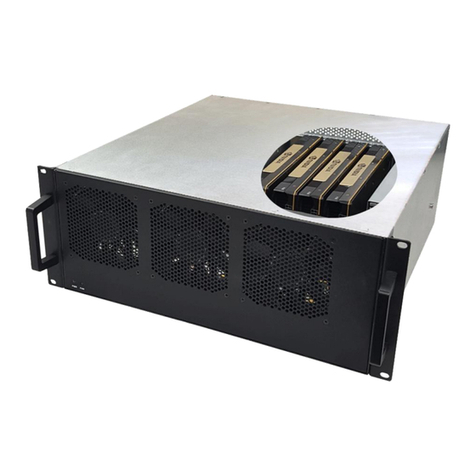
OSS ExpressBox 3450 is a 5-Slot PCI Express® Expansion System optimized for High Performance Computing (HPC) applications. Designed
specifically for GPUs, the EB3450 is equipped with OSS’s HPC backplane. . This backplane is not only PCIe Gen3, it is also x16 mechanical AND
electrical. Providing an x16 electrical backplane tremendously increases the amount of data communicated back to host computer as well as
card to card communication. The expansion system consists of a PCIe® Host Interface card, High Speed/HD IO cables, a 4U rack-mount chassis
containing a 5-Slot backplane and an Expansion Interface card, a hot swappable power supply, and high CFM cooling fans.
The ExpressBox 3450 comes with a network management interface, including a web based GUI and SNMP interface for monitoring the health of
the chassis. The design is optimized for HPC applications built with leading edge GPUs such as NVIDIA K-Series/GRID, AMD and coprocessors.
Designed for performance, the EB3450 actively directs air over the backplane. Power supplies are located underneath the chassis to ensure
maximum cooling is achieved through an unobstructed airflow path. This simple yet unique design is perfect for keeping high performance
cards operating properly even under heavy computing loads.
The small form factor allows you to bring HPC capabilities virtually anywhere. When space is a concern, the EB3450 is the perfect fit. For
ultimate customization, the EB3450 can be paired with OSS’s similarly sized expansion chassis, EB3400 or EB2400. The combination of high
speed I/O and HPC can transform any server into a fully specialized solution.
Product Name
Description
EB3450
5 peripheral slots and one host link slots (All Gen 3 x16)
1.2 EB3450 Features
•Easy “Plug and Play” installation
•PCI Express Gen 3 x16 or x8 interconnection
•All peripheral slots support full-length cards
•Status LEDs on backplane indicate active link, speed (Gen 3 or Gen 2, or Gen 1)
•Multiple power supply options with Auxiliary power connectors
•Industrial 4U rack-mount enclosure
•Chassis provides superior EMI control, vibration, shock and moisture resistance
•OSS Express I/O Manager with SNMP and built-in web graphical user interface
•Constant critical component monitoring
•Front panel status LED display

One Stop Systems
EB3450 | 9
1.3 EB3450 Technical Specification
MODEL
EB3450
- One five slot backplane mounted in 1/2 19" rack width chassis; Supports up to 4
GPUs + 1 single slot device
-Two 1200W/1500W (2400W/3000W total) PSUs. 1200W PSU per module@120V;
1500W @240V
HARDWARE
Backplane
EB3450: five peripheral slots and one host link slot (All Gen 3 x16)
Interconnect Bandwidth
PCIe Gen 3 x16: 128 Gbits/sec to all peripherals and host link
ENCLOSURE
Material
Steel Chassis
Dimension
8.5” Wide x 7.25” High (4U) x 20” Deep
HOST CONNECTION
Host side: Any PCIe based host-equipped
computer (preferably Gen 3 x16)
Expansion side: The host link is Gen 3 x16 capable and will train down to Gen 2 or 1 as
needed.
Switchless host link adapter design for minimal host/expansion latency
FANS
Two Fans
Dimension: 92mm X 92mm X 38mm Airflow: 185 CM ; fan speed adjustable through
Express I/O manager.
Speed: 11500 RPM Acoustical noise at 11500 rpm: 71 (Max) dB-A; lower db-A at lower
fan speeds.
POWER SUPPLY
1200W/1500W PSU
Additional Hot swappable 1200W/1500W AC power PSU can be ordered as spares.
The base EB 3450 is configured with full (2) PSUs
ENVIRONMENT
Ambient Temperature
0º to 50º C
Storage Temperature
-55º to 125º C
Relative Humidity
0% to 90% non-condensing
REGULATORY COMPLIANCE
FCC Class A Verified
RoHS Compliant
CE Certified
SUPPORTED OPERATING SYSTEMS
Windows
Mac OS
Linux
Solaris
Warranty
One year Warranty

One Stop Systems
EB3450 | 10
1.4 Parts List
#
Item Description
Quantity
1
Host Interface card
1
2
1or 2-meter High Speed / HD IO cable (specified at order
2
3
U.S. Standard 115V Power Cord
1 per supplied PSU
4
Expansion Interface card
1
5
Quick Start Guide
1
6
1200W/1500W Power Supply Modules (installed)
2
7
Fan (installed)
2

One Stop Systems
EB3450 | 11
1.5 Components of EB3450 unit
Once you have completed your inventory, your next step is to be familiarized with components of the OSS EB3450 expansion unit.
The expansion unit is composed of the following integral components.
1. Expansion Backplane
a. 5 PCIe x16 slot (electronic and mechanical)
b. Two designated Link-Up SLOTs for Interface card
c. Slot LEDs, Link and Activity LEDs (30 LEDs)
d. Thermistor control switch
2. Interface card
a. Expansion and Host mode DIP switch
b. Speed Toggle switches
c. Two Cable ports: one for x8 and the other is x16
3. Power Supply, redundant and hot-swappable
a. Power cord socket
b. LED status indicator
c. Locking Thumb screw
d. 9(6+2 pin) Auxiliary PCIe connectors
e. Hot swappable
4. Fans
a. 185 CFM
b. Air Flow: from outside going inside from front of chassis to rear
5. Express I/O management module
a. NetBurner
b. RJ45 port
Front panel:
1. Push button On/Off switch
2. Front Panel Status LED
3. Front Grill cover
Rear Panel:
1. PCI Express card slot opening
2. Interface card cable ports (x8 and x16)
3. Power Supply
4. Express I/O RJ-45 Ethernet port for management
5. Top cover thumb screws
6. Power Rating
7. Serial number

One Stop Systems
EB3450 | 12

One Stop Systems
EB3450 | 13
1.6 Pre-Installation Information
Before using the OSS Expansion chassis, you should perform the following steps:
•Inventory the shipping carton contents for all of the required parts
•Gather all of the necessary tools required for installation
•Read this manual
1.7 Tools Required for Installation
To complete the installation of the OSS product you will need a Phillips-head screwdriver and ESD wrist strap to prevent electrostatic discharge.

One Stop Systems
EB3450 | 14
2 Hardware Installation
The following steps will guide you through the installation of your OSS Expansion System.
CAUTION
Hardware installation shall be performed only by qualified service personnel.
Electrostatic Discharge (ESD) Warning
All add-in cards are susceptible to electrostatic discharge. When transporting the cards, it is best to carry the cards in anti-
static packaging. If you need to set a circuit card down, be sure to place it inside or on top of an anti-static surface. For
more information, see “Protecting Against Electrostatic Discharge” in the Preface.
WARNING
High voltages are present inside the expansion chassis when the unit’s power cord is plugged into an electrical outlet.
Disconnect the power cord from the AC outlet before removing the enclosure cover. Turning the system power off at the
power on/off switch does not remove power to components. High voltage is still present.
CAUTION
Before touching anything inside the enclosure, move to an ESD station and follow proper ESD procedures. Failure to do so
may result in electrostatic discharge, damaging the computer or its components. For more information, see “Protecting
Against Electrostatic Discharge” in the Preface.

One Stop Systems
EB3450 | 15
2.1 Installation-Procedures Overview
Below is the concise version on how to set up the EB3450.
1. Open Enclosure
2. Install Expansion Interface card (If not installed)
3. Install Host Interface card into host computer
4. Install Cable (Connect A to A and B to B on interface cards between the host and expansion chassis
5. Install PCIe cards, (see notes below)
6. Attach Power Cords
7. Connect to Electrical Outlet –verify adequate circuit capacity for wattage needed (this may require multiple circuits)
8. Turn on EB3450
9. Power on Computer
10. Hardware Check
11. Verify Installation (via Operating System)
NOTE
It is highly recommended to install any 3rd party PCIe cards / High Power PCIe cards after you have verified
and tested the OSS expansion is functional and there are no hardware failures.
When installing 3rd party PCIe card, start with one card first just to see if there are any software and hardware issues or incompatibility
problems that may occur. This way you can troubleshoot the problem more easily and efficiently. If everything works well and there are no
configuration issues, you can proceed with the installation of the remaining 3rd party PCIe cards.
Always refer to or read the “3rd party manufacturer installation guide” for further instructions.

One Stop Systems
EB3450 | 16
2.2 Open Enclosure
Loosen the thumbscrews that retain the top cover of the chassis and slide the lid towards you as shown below:
2.3 Install Expansion Interface Card
By default, the Expansion Interface card should already be installed in "SLOT 0-UPLINK” of the OSS Expansion board. It is set to “ON=EXP” and
configured as x16. User should not alter or change the settings of SW3. If you encounter problems, for troubleshooting purposes only check
SW3; verify the dipswitch is set to x16.
EB3450 comes with 1 Expansion Interface card. It is Gen3 x16; it has two available cable ports for linking either x8 or x16 connection.
If you need to replace or install the Expansion Interface card, follow the steps below:
1. Check the dipswitch (SW4), make sure it is set to be “ON=EXP” position. See above picture.
2. The chassis should be turned OFF.
3. Install the new Expansion Interface card.

One Stop Systems
EB3450 | 17
Plug-in the Expansion Interface card into PCIe slot#0. This is the designated slot for the Interface card. Installing the Interface card into a non-
designated slot can cause the system to malfunction.
2.4 Install Host Interface Card
Begin installation by powering down your host computer. Use the procedures for shutting down your operating system and shutting off power
to your system provided in your owner’s manual or system documentation.
2.4.1 Low Profile Bracket Installation
If your server or computer only accommodates a low profile case card , you have to change the existing mounting bracket on the Host interface
card to a low profile bracket that shipped with your system as shown below. Standard Interface card is mounted to a “full-height” bracket.
Remove the screws that hold the card to the bracket. Be sure you are using proper ESD procedures when completing this action.
Align and mount the low profile bracket.
Install the two mounting screws, do not tighten up the screws yet.
Plug in the two cables.
Alight the bracket and make the adjustment, then tighten up the screws.

One Stop Systems
EB3450 | 18
When the host computer is off and all power cords are disconnected from the AC outlet, remove the cover and prepare your host card for
insertion into a PCIe slot. Check the RED switch (SW4), Make sure it is set to OFF=HOST.
Note: The expansion chassis will NOT function if the red dipswitch on the Interface card is set to ON and the card is inserted into the host
computer. As shown from the picture above, the Host Interface card is set to OFF=HOST.
Install the two One Stop System PCIe host interface cards into the host computer. Use available x16 PCIe slot for both Host Interface cards.
Plug in the host card to the PCIe slot closest to the PCIe CPU, this allows the BIOS to enumerate the host card first. Secure it with a retaining
screw.

One Stop Systems
EB3450 | 19
There are 2 host cards available for this chassis. It is important to know how many lanes the host computer slot can support. The host card does
not need to be configured for the same number of lanes as the host computer slot.
The host card will train down to whatever the PCIe slot speed is that it recognizes. For example, if the host interface card is installed in a x8
lane card slot; leave the host card setting as is. The host computer dictates what link width and speed the expansion system will be operating.
IMPORTANT
There is no need to change the dipswitch setting when plugging in the Host Interface card into x4 or x8 PCIe slots. It is ok
to plug in the Host card into a PCIe slot with no identification whether it is GEN1, GEN2, x4 or x8. The host card will
instantly and automatically train down to whatever the speed is of the PCIe slot it recognizes.
DANGER or STOP
YOU MUST ONLY INSTALL THE PCIe HOST CARD INTO A PCI EXPRESS SLOT. Only use cards WITH brackets.
This will ensure that your PCIe host card can only be inserted into a PCIe slot. Although PCI Express cards without brackets
may fit into conventional PCI slots, you run the risk of damaging the PCI Express host card if you insert it into a PCI slot.
Please ensure that your host computer has PCI Express slots and install the host card only into a PCI Express slot.

One Stop Systems
EB3450 | 20
2.5 Connect Link Cables
The EB3450 expansion unit uses High Speed / High Density IO cables (HDLSP- High Density Low Skew Pair cable) that deliver superior
performance. It is an ideal solution for super-computing and data storage applications including servers, blade servers, and server clusters,
providing vast modularity between systems and subsystem.
The cable is available in 1-meter length.
Link Connectivity
Number of Cables
x16
Qty: 2 (Two High Speed / HD IO Cables is needed)
X8
Qty: 1 (One cable only)
Cable Specification
1
The cable provides easy interconnection for blazing system performance.
2
The cable system is also equipped with a rugged simple detent latching system allowing for the tightest cable placement.
Connect Cables to Expansion interface cards and connect the other end to Host interface cards.
•Be attentive which port to plug in the cable to.
•The interface card has two cable ports labeled with x8 A and x16 B.
•Connecting the cable to the wrong port will render the unit inoperable.
•One simple method to remember is to plug in the cable “A to A” and “B to B” ports.
CAUTION
Make sure to plug in the cable to the correct port. The Interface card has two cable ports labeled with x8 A and x16 B.
Connecting the cable to the wrong port can cause the system not to operate properly.
Table of contents
Other OSS Chassis manuals
