Thermo IEC FRENCH Press FA-078A User manual

OPERATION
MANUAL
OMFA078A
Revision 0
FRENCH® Press
Laboratory Press
Cat. No. FA-078A 120 VAC, 60 Hz
Cat. No. FA-078A-E 240 VAC, 50 Hz
Laboratory Press with Standard Pressure Cell
Cat. No. FA-080A 120 VAC, 60 Hz
Cat. No. FA-080A-E 240 VAC, 50 Hz
Laboratory Press with Mini Pressure Cell
Cat. No. FA-081A 120 VAC, 60 Hz
Cat. No. FA-081A-E 240 VAC, 50 Hz
300 Second Ave.
Needham Heights, MA 02494
Tel. (781) 449-8060 Toll Free: (800) 843-1113 Fax (781) 444-6743
Website: www.thermo.com
/
iec email: info
@
thermoiec.com
NOTE
This operator’s manual contains information, instructions and specifications for the FRENCH
Press and the 20K and 40K FRENCH Pressure Cell that were believed accurate at the time this
manual was written. However, as part of Thermo IEC’s on-going program of product
development, the specifications and operating instructions may be modified or changed from time
to time. Thermo IEC reserves the right to change such operating instructions and specifications.
Under no circumstances shall Thermo IEC be obligated to notify purchasers
of any future changes in either this or any other instructions or specifications relating to Thermo
IEC products, nor shall Thermo IEC be liable in any way for its failure to notify purchasers of such
changes.
GENERAL SAFETY NOTES USED IN THIS MANUAL
This symbol alerts you to important information about using the instrument. Be sure to
read and follow the associated instructions carefully.
This symbol alerts you to potential electrical hazards. Be sure that only qualified persons
perform the related procedures.
This symbol alerts you to a crushing pinch point, which can cause personal injury.
WARNING
Only Thermo IEC’s Pressure Cells should be used with the FRENCH
Press. Thermo IEC Pressure Cells are designed for, and must only be
used for, biological cell disruption. Use of the FRENCH Pressure Cells
and Press for other uses may create hazardous conditions resulting in
severe personal injury, death or property damage.
NOTE: The contact of the piston and the closure plug at high pressure can
damage the piston, closure plug, cell body, or all three. Damage caused by
piston/closure plug contact at high pressure is not covered by the product
warranty.
PRECAUTION: During the assembly and fill process, do not allow the piston to pick-up
granules (e.g., sand, glass, dirt, etc.). A contaminated piston will
irreversibly damage the inside of the cell.
WARNING: FRENCH Press and FRENCH Pressure Cells are to be used only with
samples of plant or animal cells. DO NOT put inappropriate materials (e.g.,
sand, glass, dirt, etc.) in the cell as this could result in an explosion,
causing bodily injury.

WARRANTY
Thermo IEC wants you (“Customer”) to be satisfied with the quality of your Thermo IEC FRENCH
Press and related accessories (the “Products”). Thermo IEC warrants that the Products will
operate substantially in conformance with our published specifications, when subjected to normal,
proper and intended usage by properly trained personnel, for a period of ninety (90) days from
the date of shipment from Thermo IEC (the “Warranty Period”). Thermo IEC agrees during the
Warranty Period, provided it is promptly notified in writing upon the discovery of any defect and
further provided that all costs of returning the defective Product to Thermo IEC are pre-paid by
Customer, to repair or replace, at Thermo IEC’s option, defective Products so as to cause the
same to operate in substantial conformance with said specifications. Replacement parts may be
new or refurbished, at the election of the Thermo IEC. All replaced parts shall become the
property of Thermo IEC. Lubricants, o-rings, nylon balls and other expendable items are
expressly excluded from the warranty. Thermo IEC’s sole liability with respect to equipment,
materials, parts or software furnished to Thermo IEC by third party suppliers shall be limited to
the assignment by Thermo IEC to Customer of any such third party supplier’s warranty, to the
extent the same is assignable. In no event shall Thermo IEC have any obligation to make
repairs, replacements or corrections required, in whole or in part, as the result of (i) normal wear
and tear, (ii) accident, disaster or event of force majeure, (iii) misuse, fault or negligence of or by
Customer, (iv) use of the Products in a manner for which they were not designed, (v) causes
external to the Products such as, but not limited to, power failure or electrical power surges, (vi)
improper storage of the Products or (vii) use of the Products in combination with equipment or
software not supplied by Thermo IEC. If Thermo IEC determines that Products for which
Customer has requested warranty services are not covered by the warranty hereunder, Customer
shall pay or reimburse Thermo IEC for all costs of investigating and responding to such request at
Thermo IEC’s then prevailing time and material rates. If Thermo IEC provides repair services or
replacement parts that are not covered by the warranty, Customer shall pay Thermo IEC
therefore at Thermo IEC’s then prevailing time and material rates. ANY INSTALLATION,
MAINTENANCE, REPAIR, SERVICE, RELOCATION OR ALTERATION TO OR OF, OR OTHER
TAMPERING WITH, THE PRODUCTS PERFORMED BY ANY PERSON OR ENTITY OTHER
THAN THERMO IEC WITHOUT THERMO IEC’S PRIOR WRITTEN APPROVAL, OR ANY USE
OF REPLACEMENT PARTS NOT SUPPLIED BY THERMO IEC, SHALL IMMEDIATELY VOID
AND CANCEL ALL WARRANTIES WITH RESPECT TO THE AFFECTED PRODUCTS.
THE OBLIGATION CREATED BY THIS WARRANTY TO REPAIR OR REPLACE A DEFECTIVE
PRODUCT SHALL BE THE SOLE REMEDY OF CUSTOMER IN THE EVENT OF A DEFECTIVE
PRODUCT. EXCEPT AS EXPRESSLY PROVIDED IN THIS WARRANTY, THERMO IEC
DISCLAIMS ALL WARRANTIES, WHETHER EXPRESS OR IMPLIED, ORAL OR WRITTEN,
WITH RESPECT TO THE PRODUCT, INCLUDING WITHOUT LIMITATION ALL IMPLIED
WARRANTIES OF MERCHANTABILITY OR FITNESS FOR ANY PARTICULAR PURPOSE.
THERMO IEC DOES NOT WARRANT THAT THE PRODUCT IS ERROR-FREE OR WILL
ACCOMPLISH ANY PARTICULAR RESULT.
NOTE: ALL CELL PARTS RETURNED TO THERMO IEC MUST BE AUTOCLAVED.
CONDITION OF RETURNED EQUIPMENT
Before returning equipment to Thermo IEC, you must contact Thermo IEC's or your dealer’s
service department and receive a return goods authorization (RGA). All returned units must be
decontaminated, free of radioactivity, and free of hazardous and infectious materials. The RGA
paperwork includes a certificate for you to sign indicating that you have performed these steps.
Thermo IEC will not accept the shipment unless this signed certificate accompanies it. You must
prepay transportation to the service depot.

IMPORTANT NOTE
If you receive any damaged items, forward an immediate request to the delivering carrier to
perform an inspection and prepare a concealed damage report.
Do not dispose of any containers or packing material until the contents have been verified. Report
to Thermo IEC the nature and extent of any damage to the instrument. Give the instrument’s
serial and catalog number. Action will be initiated to repair or replace damaged parts or
instructions issued for the return of the instrument.
The responsibility of Thermo IEC ends with delivery to the first carrier. All claims for loss, damage
or non-delivery must be made against the delivering carrier within ten (10) days of receipt of
shipment.

TABLE OF CONTENTS
INTRODUCTION............................................................................................................... 1
A. WHY THE FRENCH PRESSURE CELL WORKS ............................................... 1
B. THE FRENCH PRESSURE CELLS AND THEIR RAPID-FILL KITS ................... 1
C. THE FRENCH PRESSURE CELL PRESS..........................................................3
D. PRINCIPLES OF OPERATION ........................................................................... 4
II. THE FRENCH PRESSURE CELL PRESS............................................................. 8
A. DESCRIPTION .................................................................................................... 8
B. ASSEMBLY........................................................................................................ 10
C. INSTALLATION ................................................................................................. 10
D. OPERATION...................................................................................................... 11
III. THE 40K MANUAL-FILL CELL............................................................................ 14
A. UNPACKING...................................................................................................... 14
B. ASSEMBLY........................................................................................................ 15
C. INSTALLATION ................................................................................................. 17
D. OPERATION...................................................................................................... 18
IV. THE 40K RAPID-FILL KIT....................................................................................20
A. UNPACKING...................................................................................................... 20
B. ASSEMBLY........................................................................................................ 20
C. INSTALLATION ................................................................................................. 22
D. OPERATION...................................................................................................... 23
V. THE FRENCH PRESSURE MINI-CELL ............................................................... 25
A. UNPACKING...................................................................................................... 25
B. ASSEMBLY........................................................................................................ 26
C. INSTALLATION ................................................................................................. 27
D. OPERATION...................................................................................................... 27
VI. MAINTENANCE.................................................................................................... 29
A. THE FRENCH PRESSURE CELL PRESS........................................................29
B. THE FRENCH PRESSURE CELLS................................................................... 32
C. THE RAPID FILL KIT .........................................................................................35
VII. SAFEGUARDS ..................................................................................................... 38
A. THE PRESS....................................................................................................... 38
B. THE CELLS ....................................................................................................... 38
VIII. SPECIFICATIONS ............................................................................................. 40

INTRODUCTION
A. WHY THE FRENCH PRESSURE CELL WORKS
Internal FRENCH Pressure Cell pressure increases as the pressure developed by the Laboratory
Press increases. The intracellular pressure increases as well. As the sample is dispensed
through the sample outlet tube, the external pressure on the cells' walls drops rapidly toward
atmospheric pressure. This pressure differential causes the cell wall membrane to burst,
releasing the intra-cellular contents. The now-free cellular artifacts can be collected and
separated as required.
Note that as the sample is dispensed from the FRENCH Pressure Cell, the internal pressure
begins to drop. In order to ensure best disruption of cell walls, it is important to release the
sample slowly (approximately 15 drops/minute rate). Slow release allows for a much slower
decrease in the FRENCH Pressure Cell's internal pressure. At a slow sample release rate, the
operator can better maintain the FRENCH Pressure Cell's internal pressure at the desired
operating pressure.
It is also important that the FRENCH Pressure Cell piston NOT be allowed to bottom-out against
the closure plug at the bottom of the cell when operating at high pressure. This may damage the
piston, closure plug, and possibly the FRENCH Pressure Cell itself. Laboratory Press pressure
should be reduced prior to the piston making contact with the closure plug; several millimeters
distance protects the FRENCH Pressure Cell from damage and still allows for dispensing with
minimum sample waste.
WARNING: ONLY THERMO IEC'S PRESSURE CELLS SHOULD BE USED WITH THE
FRENCH PRESS. THERMO IEC'S PRESSURE CELLS ARE DESIGNED
FOR, AND MUST ONLY BE USED FOR, BIOLOGICAL CELL DISRUPTION.
USE OF THE FRENCH PRESSURE CELLS AND PRESS FOR OTHER USES
MAY CREATE HAZARDOUS CONDITIONS RESULTING IN SEVERE
PERSONAL INJURY, DEATH, OR PROPERTY DAMAGE.
B. THE FRENCH PRESSURE CELLS AND THEIR RAPID-FILL KITS
The FRENCH Pressure Cell is a dispersion unit for disintegrating chloroplast material, blood cells,
unicellular organisms, homogenates of animal tissue, and other biological particles. Use of the
pressure cell allows destruction of the cellular walls of a sample while leaving the cell nucleus
undisturbed. FRENCH Pressure Cells are available in manual-fill and rapid-fill configurations.
Manual-Fill 40K Cell (FA-032) Manual-Fill Mini-Cell (FA-003)
Maximum Working Pressure = 40,000 psi Maximum Working Pressure = 20,000 psi
Cell Capacity = 35 ml Maximum Compressive Force on piston =
2,200 lbs
A loading stand is provided for filling the cell. Cell Capacity = 3.7 ml
See Figures 1 and 2. See Figure 4. (Rapid-Fill Kit is not available.)
Rapid-Fill Kit (FA-021) for the FA-031 40K cell
See Figure 3.
1

Figure 1
The 40K and 20K Manual-Fill Cell
Figure 2
The 20K Cell in filling position
Figure 3
The 40K and discontinued 20K Cell with Rapid
Fill Kit
Figure 4
The Mini-Cell
2

C. THE FRENCH PRESSURE CELL PRESS
The FRENCH Pressure Cell Press is a hydraulic press which uses control valves and a motor-
driven pump to vary hydraulic pressure generated by the press (see Figure 5).
The Press offers the advantages of dual-range, single-control pressure selection and
fully-regulated working pressure through the entire operating stroke. These special features
differentiate the motor-driven FRENCH Pressure Cell Press from manual presses.
The Press is designed for use with the FRENCH Pressure Cells manufactured by Thermo IEC to
produce a selected pounds-per-square inch (psi) value inside a FRENCH Pressure Cell. It can
accommodate both 1-in and 3/8-in diameter piston FRENCH Pressure Cells.
When the FRENCH Press and Pressure Cell are used, the following table shows the approximate
factor difference between the press gauge pressure (psig) and the cell internal pressure at MED
and HIGH range settings.
Internal Cell Pressure
FRENCH Pressure Cell
Piston Diameter MED RANGE
(Gauge pressure x Factor)
HIGH RANGE
(Gauge pressure x Factor)
1"
(40K Cell)
psig x 3.1
psig x 16.0
3/8"
(Mini-cell)
psig x 21.7
psig x 113.8
(Do NOT use the HIGH
Range with the Mini-Cell.)
Figure 5
The FRENCH Pressure Cell Press
3

D. PRINCIPLES OF OPERATION
1. 40K Cell
In the following discussion, it is assumed that the FRENCH 40K Pressure Cell (1-in piston) is
mounted properly in the cell holder, and the cell has been filled with a sample and cleared of air
bubbles.
Before pressurizing the FRENCH Pressure Cell, determine the gauge pressure required to
produce a known working pressure inside the cell. Note the pressure gauge on the FRENCH
Pressure Cell pump indicates pressure on a hydraulic cylinder piston inside the press. The
gauge pressure is not the actual working pressure in the FRENCH Pressure Cell. The pressure
produced in the cell is proportional to the ratio of the areas (sq in) of the hydraulic cylinder piston
in the press and the piston in the FRENCH Pressure Cell, as indicated by the following equation.
Pc =
(Phcp)(Ahcp)
Afcp
where: Pc
Phcp
Ahcp
Afcp
=
=
=
=
working pressure in the FRENCH Pressure Cell (lbs per sq in)
pressure on the hydraulic cylinder piston
area (πr2) of hydraulic cylinder piston
area (πr2) of FRENCH pressure cell piston
In the following example, assume that the pressure gauge reading (Phcp) is 1,250 psi with the
RATIO SELECTOR lever set at HIGH. This pressure is applied to a hydraulic cylinder that has a
diameter of 4 in (Ahcp=12.56 sq in), and a FRENCH Pressure Cell with a 1-in diameter
(Afcp=0.785 sq in). The working pressure in the FRENCH Pressure Cell is:
P
c= (1250) 12.56 = 20,000 psi
0.785
When the RATIO SELECTOR lever is set to MED, hydraulic pressure is applied to both sides of
the 4-in piston. The shaft that connects the piston to the press platen has a 1.75-in diameter;
therefore, the effective area on top of the piston is reduced from 12.56 sq in to 10.16 sq in. Since
equal pressure is applied to both the top of the piston (10.16 sq in) and the bottom of the piston
(12.56 sq in), then the gauge pressure multiplied by 2.40 (12.56 sq in minus 10.16 sq in) equals
compressive force in psi. Again, with the equation and values shown above but substituting 2.40
for Ahcp, the working pressure inside the FRENCH Pressure Cell would be 3,822 psi.
The calculations described on this page do not consider the weight of the platen or cell, or
friction. The actual working pressure inside the FRENCH Pressure Cell would be
somewhat lower than the calculated value.
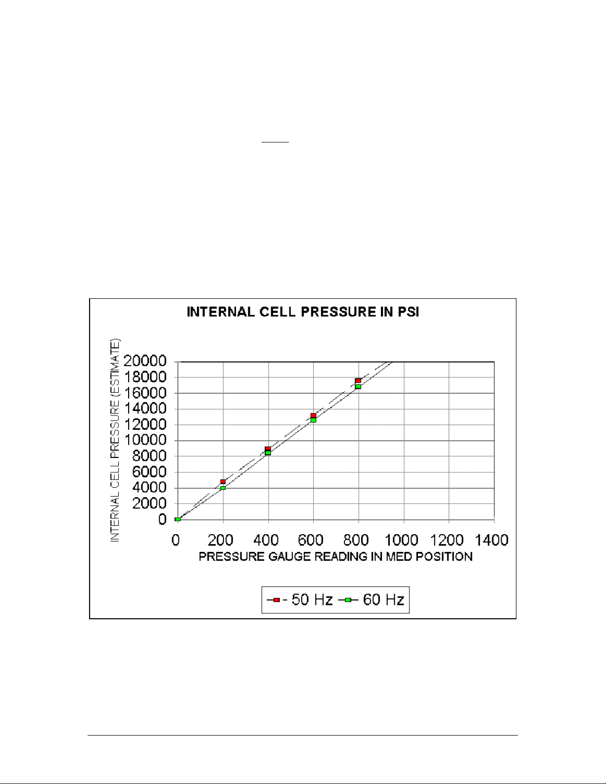
For your convenience, the relationship between the gauge pressure and cell pressure is
shown graphically in greater detail in Figures 6 and 7.
4
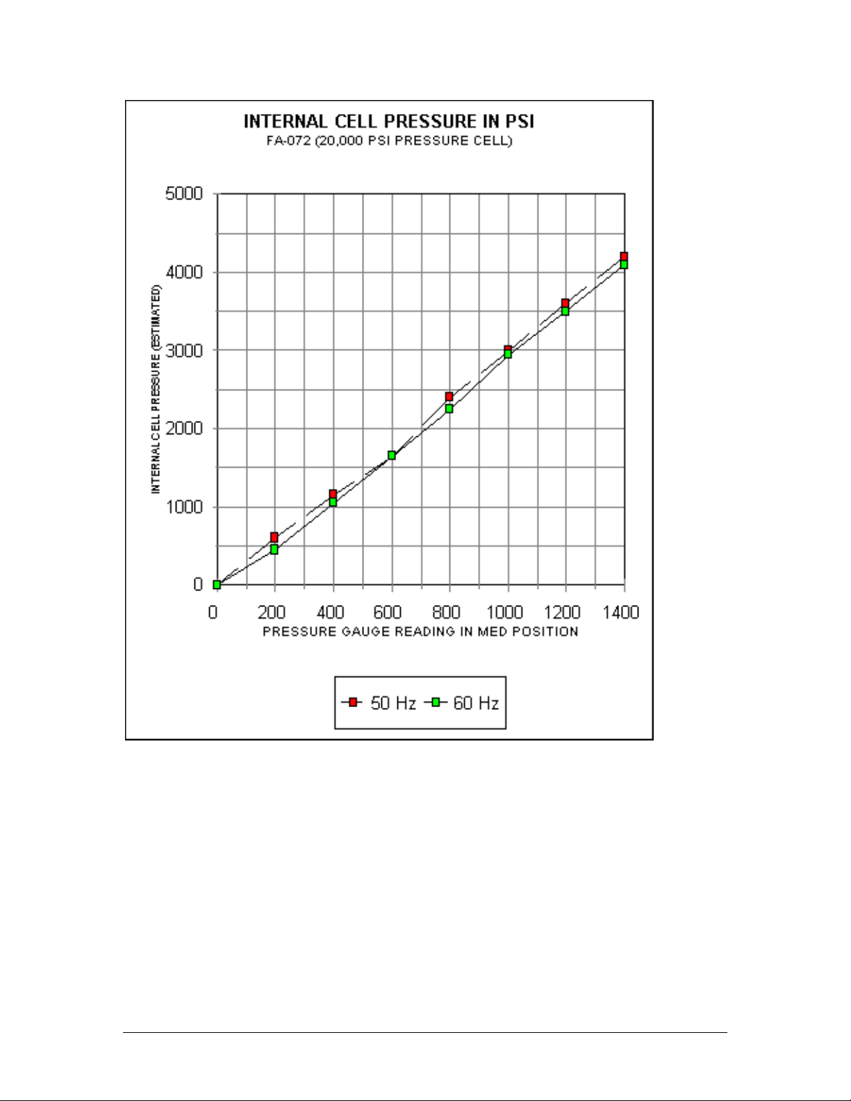
Figure 6
Internal Cell Pressure in psi, FA-032 (40,000 psi pressure cell)
5

Figure 7
Internal Cell Pressure in psi, FA-032 (40,000 psi pressure cell)
2. 20K Mini-Cell specifications
In the following discussion, it is assumed that the FRENCH 20K Pressure Mini-Cell is mounted
properly in the cell holder, and the cell has been filled with a sample and cleared of air bubbles.
• Do not exceed 20,000 psi pressure in the cell or damage occurs. This is a reading of
900 lbs on the gauge of the FRENCH Pressure Cell Press in MED ratio position.
When using the FRENCH Pressure Cell Press, refer to the graph (Figure 8) or to the table
located on the front of the press to determine the desired gauge pressure setting necessary to
achieve the required pressure in the cell.
WARNING: USE MED PRESSURE ONLY. THE MAXIMUM FORCE ON THE
PISTON IS 2200 LBS (A READING OF 900 LBS ON THE FRENCH
PRESS WITH THE PRESS IN MED POSITION). A SPACER (FA-010)
IS REQUIRED FOR USE WITH THE FRENCH PRESSURE CELL
PRESS. THE SPACER'S ALIGNING PINS CENTER THE CELL
DIRECTLY ABOVE THE ACTUATING CYLINDER OF THE PRESS.
The cell clamp on the press secures the cell body to the lower platen. If no locking mechanism is
available on the press that is being used take extreme care that the pressure is not released on
the press while there is still hydraulic pressure in the cell. This can cause the cell body to ride up
off the cell closure plug and either blow out the o-ring seal or bend that section of the closure plug
that fits into the cell body.
6
If a manufacturer's press other than Thermo IEC is used, please note the gauge reading may
indicate the pressure on the hydraulic ram inside the press. The working pressure inside the cell
may be calculated using the following equation:
π
r2
Pc = Pr•0.1105
where: Pc= working pressure inside the cell
Pr= pressure on the hydraulic piston
r = radius of the hydraulic piston
0.1105 = the surface area of the mini-cell piston
Again, if another manufacturer's press is used, it is imperative that the platens be parallel and the
cell be centered to prevent any side force on the piston. Forces other than a straight line though
the cell could cause the piston to bend and the cell could be thrown from the press causing injury
to the operator.
Figure 8
Internal Cell Pressure in psi, FA-003 (Miniature Pressure Cell)
7

II. THE FRENCH PRESSURE CELL PRESS
A. DESCRIPTION
1. Side Panel Access Door Opens to gain access to hydraulic fluid reservoir inside
the press.
2.
Ratio Selector Valve
A-5024
MED or HIGH position is used in conjunction with
PRESSURE INCREASE CONTROL to control pressure
against lower platen (item 7). DOWN position permits
lower platen to descend for pressure cell installation or
removal.
3.
PUMP Switch
E-0632
Controls application of AC power to pump motor inside
unit.
110V 10 AMP circuit breaker switch.
220V 6 AMP circuit breaker switch.
4. PRESSURE INCREASE
control
A-5023
Used in conjunction with RATIO SELECTOR control lever
to regulate amount of pressure applied to lower platen
(item 7). Clockwise rotation increases pressure, while
counterclockwise rotation decreases pressure.
5. Pressure gauge, 0-3000 psi
A-5722
Indicates pressure value at RATIO SELECTOR valve.
The actual pressure value applied to lower platen
depends upon the position of RATIO SELECTOR lever
(HIGH, MED or DOWN).
6. Lower platen
PC-305
Moves up or down to permit cell installation and
subsequent pressurization to selected psi value. Three
alignment pins on lower platen are used to position lower
section of cell body in press.
7. Cell clamp
Support Rods (2 required)
PC-204
PC-418 Extensions
Provides support for the cell clamp. Remove rods, install
rod extensions, replace rods for use with the 40K Cell.
8. Aligning Pins (3 required)
PC-303
Centers the cell in the press.
9. Cell Clamp with thumb screws
PC-190
Locks top of pressure cell in position to ensure proper cell
alignment during pressurization.
10. Upper Platen
PC-306
Provides a mechanical stop for the top of the pressure
cell piston. Used also in conjunction with the spacer and
piston retainer (not supplied) for positioning and housing
these components when the rapid-fill pressure cells are
used in the press.
11. Line cord
120V 335001-785
220V 335447-695
240V 335401-754
Inputs AC power to the unit.
U.S. Plug
Continental Europe Plug
U.K. Plug
8
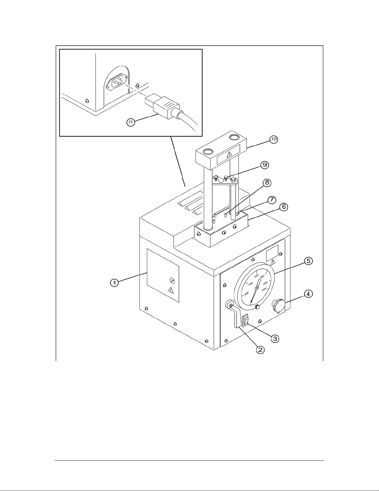
Figure 9
Controls and indicators of the FRENCH Pressure Cell Press
9

B. ASSEMBLY
The FRENCH Pressure Cell Press is completely assembled when shipped.
C. INSTALLATION
The three-prong power plug supplied grounds the press and polarizes the connection. Prior to
connecting the FRENCH Pressure Cell Press to an AC source, ensure that the following
requirements are met:
a. Install only on a level surface capable of supporting the 240-lb press.
b. Verify that the 60 Hz power outlet can provide 15 amperes, 120V ±10% AC service; or
when operating from 50 Hz, the power outlet must be capable of supplying 10 amperes at
220 or 240V ±10% AC.
c. Use only a three-hole, grounded power outlet.
d. Verify that the ground conductor is continuous to the main power panel which should be
grounded directly to a metal water pipe or other earth ground.
e. Check the power outlet polarity and have the wiring changed, if required, to ensure
proper polarity.
f. Ensure that no voltage gradient exists between the ground and neutral conductors.
1. Unpack and verify the contents with the parts list in this section.
2. Position the press at a convenient location near a source of AC Power.
3. Locate the access door on the left-hand side of the press; open the panel door.
4. Remove the tape from the oil reservoir cap. The press is shipped with 450 SSU, Hydro 147,
Viscosity –100. For refill, use a high-grade industrial oil such as Mobil DTE 26 or Shell
Tellus 33.
PRECAUTION: For operation in ambient temperatures above 20°C (68°F), the
hydraulic fluid supplied with the press (viscosity of 250-300 saybolt
seconds universal (SSU) at 38°C (100°F) is satisfactory. If operation
in colder temperatures is anticipated, the use of a lower viscosity
hydraulic fluid, such as Mobil DTE 24 or Shell Tellus 25 (not supplied),
will be necessary for viscosity of 150 SSU.
5. Check the fluid level in the reservoir using the dipstick indicator on the reservoir cap. Ensure
that a sufficient amount of hydraulic fluid is in the reservoir (fluid level above mark on
dipstick – see Figure 10).
WARNING: IF YOU OPERATE THE PRESS WITHOUT OIL, YOU WILL
IRREVERSIBLY DAMAGE THE HYDRAULIC PUMP.
6. Replace the cap on the reservoir. Wipe any fluid spills from the exterior of the press cabinet.
Close the access panel door.
7. Set PUMP switch on the front panel of the press to OFF. Connect the FRENCH Pressure
Cell Press line cord to the power connector on the rear panel.
10

CAUTION: To eliminate the possibility of damage to the press pump motor,
ensure that the AC line voltage and operating frequency is correct for
the particular model of the FRENCH Pressure Cell Press. Refer to
the model numbers.
WARNING: THE POWER OUTLET MUST BE GROUNDED PROPERLY AND
POLARIZED. IMPROPER GROUNDING COULD RESULT IN
ELECTRIC SHOCK.
8. Plug the line cord into the AC power outlet.
9. The FRENCH Pressure Cell Press is now ready for operation. Perform the procedures
directed in OPERATION to verify operation of the unit.
Figure 10
Hydraulic Fluid Reservoir
Access through side panel
access door
D. OPERATION
The following procedure assumes that the FRENCH Pressure Cell Press has been installed using
the instruction given in INSTALLATION. It is also assumed that the FRENCH Pressure Cell is
installed in the press as described in installation sections of this manual.
1. Set PUMP switch to OFF. Unplug the line cord.
CAUTION: Check the hydraulic fluid reservoir for the proper level before
operating the press.
2. Open the side door and remove the reservoir cap. Check the level of hydraulic fluid in the
reservoir and add hydraulic fluid of proper viscosity, if necessary. Replace the reservoir cap
and close the side panel door (see Figure 10).
11

3. Using the appropriate graph in Figures 6-8 or the table located on the front of the press,
determine the gauge pressure required to produce a specific value of working pressure in
the cell.
CAUTION: Do not operate the cell above its pressure rating.
4. Plug in the line cord. Turn PRESSURE INCREASE control fully counterclockwise and set
RATIO SELECTOR to DOWN.
5. Set PUMP switch to ON and turn PRESSURE INCREASE clockwise until the gauge
indicates the pressure value selected in step 3.
PRECAUTION: Be patient. It will take a few moments for the pump to fill and
pressurize the internal hydraulics of the press.
6. Set RATIO SELECTOR control lever to either MED or HIGH, the lever position again being
determined by the pressure value selected in step 3.
7. Check the cell alignment in the press as the lower platen rises. Ensure that the cell piston
squarely strikes under the upper platen. If the pressure cell needs to b realigned, go to
step 8.
WARNING: ENSURE THAT THE T-HANDLE ON THE PRESSURE CELL PISTON
IS ALIGNED PERPENDICULAR TO THE CELL CLAMP
THUMBSCREWS. FAILURE TO PROPERLY ALIGN THE PISTON
CAN CAUSE THE PISTON HANDLE AND THUMB SCREWS TO
MEET, BENDING THE HANDLE AND POSSIBLY CAUSING THE
THUMBSCREWS TO BREAK AND BECOME AIRBORNE. IF THE
PRESSURE CELL NEEDS TO BE REALIGNED, GO TO STEP 8. IF
NOT, PROCEED TO THE NEXT STEP. FAILURE TO FOLLOW THIS
PROCEDURE WILL VOID THE WARRANTY.
8. Lower the platen by placing the three-position control lever to DOWN. Realign the cell in the
press. See detailed mounting instructions in the pressure cell's INSTALLATION section if
necessary.
9. Recheck the psi reading on the pressure gauge to ensure that it indicates the predetermined
pressure value. Open the flow valve on the cell slightly so liquid flows from the sample
outlet tube at a rate of approximately 15 drops per minute. This is the maximum
recommended flow rate.
NOTE: The flow valve is extremely sensitive. To achieve the desired flow rate, gently
finger tap the valve handle.
SPECIAL
PRECAUTION:
In some applications, the FRENCH Pressure Cell and the suspension
of biological material are cooled to sub-zero temperatures causing the
formation of ice crystals. Ice crystals may remain unbroken even at
high pressures, and when the flow valve is opened to release the
pressure, the out-flow of the suspension may be blocked by these
crystals. Sometimes, an uneven flow of the suspension is due to the
presence of ice crystals in the flow stream. This may cause a sudden
pressure drop. In such a situation you need to repeat this procedure.
12

In general, to get an even breakage, ensure:
• that you do not close the flow valve too tightly when filling the cell with the suspension,
• that you open the flow valve gently and cautiously so that the flow rate does not exceed
approximately 15 drops per minute. The pressure tends to drop rather quickly toward the
end of the run, you may want to close the flow valve slightly by turning it clockwise before
opening it again.
Also, at the end of the run the flow stream may contain air bubbles causing the suspension to
squirt into the collection tube. The sample may spill out and be lost. Be careful to position the
sample outlet tube at a distance above the sample.
10. After the sample has been processed, lower the platen by placing the RATIO SELECTOR
control lever to DOWN.
There will be some sample loss due to material left in the valve ports and drip tube. Do not
try to squeeze out the last drop sample. You will damage the piston, closure plug and cell
body.
11. Unless you are doing other tests, when the platen reaches its lowest position, reduce the
system pressure to zero by turning the PRESSURE INCREASE control fully
counterclockwise. Then set the pump switch to OFF.
NOTE: For certain combinations of pressure and temperature, it is possible for the
temperatures of the hydraulic fluid to increase to a point where its viscosity is
lowered and the press in unable to maintain sufficient pressure for the period
of time. Turning off the pump motor corrects this condition by allowing the
hydraulic fluid to cool down and regain its viscosity. If the press blows a fuse,
please verify that the pressure increase control is fully counterclockwise (zero
pressure) before you turn the press back on.
12. Remove the cell from the press when all the processing is complete. Clean and store the
Pressure Cell using the instructions in the MAINTENANCE section.
13. Check the exterior of the press. Wipe any hydraulic fluid or sample spills from the press
surface. See the MAINTENANCE section for specific cleaning procedures.
13

III. THE 40K MANUAL-FILL CELL
A. UNPACKING
Unpack the 40K cell. Check off the parts from the list below. If the equipment is received in
damaged condition, forward an immediate request to the delivering carrier to perform an
inspection and prepare a concealed-damage report. Do not destroy the container or packing
material until the contents have been verified.
Concurrently, report to Thermo IEC the nature and extent of the damage incurred. Give the
instrument's serial and part numbers, so that action may be initiated to repair or replace damaged
parts or instructions issued for the return of the instrument. Do not return the damaged goods to
Thermo IEC without first securing proper authorization from the company.
The responsibility of Thermo IEC ends with the delivery to the first carrier; all claims for loss,
damage, or non-delivery must be made against the delivering carrier within ten days of the receipt
of the shipment.
PACKING LIST FOR THE 40K CELL (FA-031)
DESCRIPTION QUANTITY PART NUMBER
Snap Ring Pliers 1 W-0106
Sample Outlet Tube 1 PC-113
Cell Body 1 PC-400
Closure Plug Assembly 1 PC-436
Piston Assembly 1 PC-172
Flow Valve Assembly 1 PC-435
-O-ring Pkg of 10 FA-931
-Back-up ring Pkg of 10 FA-932
Base with feet 1 PC-124
Post with H-0106 screw 3 PC-116
Envelope with
-screw
-washer
1
1
H-0107
H-0177
Certification sheet 1 Y-0010
Operator's Manual 1 OMFA078A
14

B. ASSEMBLY
The following instructions are to install the 40K cell.
Use the exploded diagrams in Figures 11 and 12 to reference the parts of the cell. Please take
careful note of the precautions as they can prevent future damage to the cell.
Only the PC-435 o-ring style flow valve assembly can be used to 40,000 psi
PRECAUTION: For the 40K, the valve should be finger tight. Excessive pressure to
tighten the valve may distort the valve seat and cause leaking.
Figure 11
Exploded diagram of the 40K Manual-fill assembly
15
This manual suits for next models
5
Table of contents
Other Thermo IEC Laboratory Equipment manuals


