Scientifica MDU Manual instruction

Page 1of 58
Multiphoton
Detection Unit (MDU)
Setup and operation manual
Revision 1.0
Manual Part No.: S-MDU-MANUAL

Page 2of 58
Contents
Note: This manual describes the features, functions and operation of the Multiphoton Detection Unit (MDU) and
associated devices. Before use, carefully read this manual, directions for all accessories, all precautionary information
and specifications.
1.0 Introduction...............................................................................................................................................4
1.1 Handling Scientifica equipment –precautions.........................................................................................4
1.2 The Scientifica Multiphoton Detection Unit (MDU)...................................................................................5
1.2.1 Product overview..............................................................................................................................5
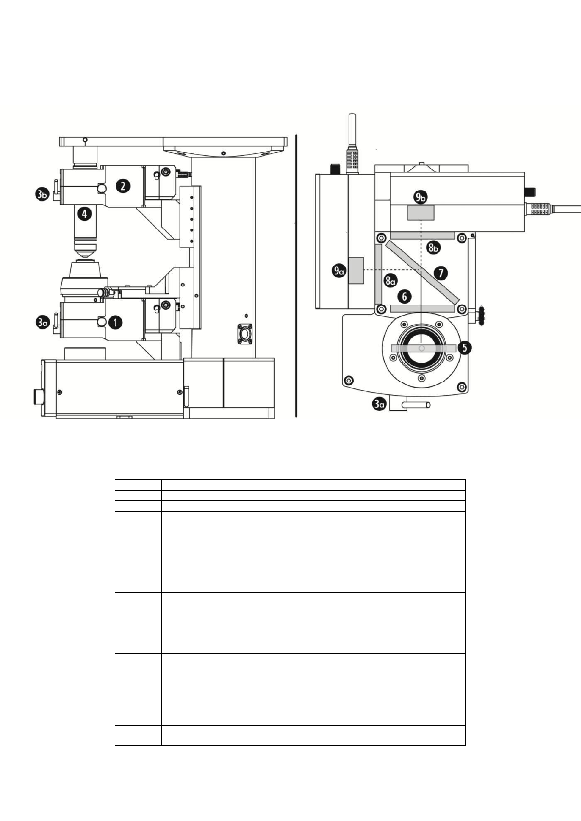
1.2.2 Product Walkthrough........................................................................................................................7
2.0 Packing List...............................................................................................................................................8
2.1 Standard items........................................................................................................................................8
2.1.1 Optical block features.....................................................................................................................10
2.1.2 Detector module features ...............................................................................................................12
2.1.3 Control racks..................................................................................................................................14
3.0 Mechanical setup....................................................................................................................................16
3.1 Fitting the above-stage MDU to the SliceScope ....................................................................................16
3.2 Above-stage variant (fixed objective).....................................................................................................18
3.2.1 Checks and preparation .................................................................................................................18
3.2.2 Fitting Objectives............................................................................................................................18
3.2.3 Direct objective attachment ............................................................................................................19
3.3 Above-stage variant manual with manual objective changer (in vivo)....................................................20
3.4 Above-stage variant with Motorised Objective Changer (MOC).............................................................22
3.4.1 Checks and Preparation.................................................................................................................23
3.4.2 Fitting a DIC Prism .........................................................................................................................23
3.4.3 Removing the rear PMT module.....................................................................................................23
3.4.4 Removing the detection module and bracket from the MOC...........................................................24
3.4.5 MOC Variant Reassembly..............................................................................................................26
3.4.6 Re-assembly of the rear PMT module ............................................................................................28
3.4.7 Installation of MOC variant onto the SliceScope.............................................................................28
3.4.8 Objective installation.......................................................................................................................29
3.5 Substage variant ..................................................................................................................................30
3.5.1 Preparation.....................................................................................................................................30
3.5.2 Installation of substage variant onto SliceScope.............................................................................32
3.5.3 Fitting the Condenser to substage variant ......................................................................................34
3.6 Filter Cube Installation...........................................................................................................................35
3.6.1 Filter Cube Population....................................................................................................................35
3.6.2 Fitting the cube to the carrier.........................................................................................................35
3.6.3 Installation in the Optical Block.......................................................................................................36
3.6.4 Extraction of the filter cube and carrier ...........................................................................................37
4.0 Optical System Preparation ...................................................................................................................38
4.1 Transmission Viewing ...........................................................................................................................38
4.2 Transmitted Laser Imaging....................................................................................................................38
4.3 Laser Beam Delivery.............................................................................................................................38
4.4 Control Software and Data Acquisition..................................................................................................39
5.0 Electrical setup .......................................................................................................................................40
5.1 Electrical setup - controller connections ................................................................................................40
5.1.1 Typical electrical configuration for complete system.......................................................................41
6.0 Operation.................................................................................................................................................42
6.1 Powering up the system........................................................................................................................42
6.1.1 Before switching on........................................................................................................................42
6.1.2 Switch-on routine............................................................................................................................42

Page 3of 58
6.1.3 Temporary switch-off procedure.....................................................................................................43
6.1.4 Safe switch-off procedure...............................................................................................................43
7.0 Troubleshooting......................................................................................................................................44
8.0 Specifications..........................................................................................................................................51
8.1 Above-Stage Variant with fixed objective and U-AAC condenser..........................................................51
8.2 Above-Stage MOC Variant with U-AAC condenser ...............................................................................52
Notes.......................................................................................................................................................52
8.3 Above-Stage Fixed Objective Variant with Substage variant.................................................................53
Notes.......................................................................................................................................................53
8.4 Above-Stage Variant with MOC and Substage Variant..........................................................................54
9. Appendix: ..................................................................................................................................................54
9.1 Removing and Replacing a Detector Module.........................................................................................54
9.2 Detector Module removal ......................................................................................................................55
9.3 Detector Module Replacement..............................................................................................................56
10.0 Warranty, Technical Queries and Returns ..........................................................................................57
11.0 About Scientifica...................................................................................................................................58

Page 4of 58
1.0 Introduction
1.1 Handling Scientifica equipment –precautions
This section contains important safety information related to general use of the Scientifica
MDU. The MDU is a piece of scientific equipment and as such requires care when handling.
Adjustment or removal of any screws or components other than those noted in
this manual can adversely affect the performance and operation of your device and
may invalidate your warranty.
High Voltage Hazard Warning
The PMTs in the detector modules operate with voltages of up to -1000 V. Whilst the detector modules are
closed, there is no risk to the user from these voltages, but a serious risk to health might occur should the
module be opened and the safety interlock defeated.
Please do not open the detectors!
PMT Over-drive caution
The preamplifiers integrated within each detector module have sufficient gain in most cases to saturate
(generate full-scale output signal) well before the PMT delivers its maximum safe output current. The data
acquisition system can be set up to saturate before full-scale signals are attained. Some detector variants
may be fitted with an average output current trip circuit that cuts power if dangerous signal levels are
encountered. Prolonged operation above, or near the maximum, rated current output will damage the PMTs or
give rise to excessive noise.
PMT Over-exposure caution
PMTs operate best when kept cool, under power and in the dark! Exposure to bright lights can lead to
damage and reduced sensitivity, as well as excessive noise. The system is designed to prevent accidental
exposure to bright lights and to cut off the high-voltage should this possibility arise. Do not attempt to defeat
the safety interlocks or to disassemble the main optical block. Make proper use of the “master safety”
switch on the controller and move the laser / visible dichroic mirror to the “safe” (withdrawn) position whenever
working on the microscope with the lights on.
To prevent inadvertent damage to the PMTs, the system incorporates various safety features: the PMTs are
cut off whenever the laser dichroic mirror is withdrawn from the beam, and as a secondary precaution the
optical path is blocked by a mechanical shutter which keeps the detectors dark and maintains their noise at a
low level. In addition, the PMTs are cut off whenever the filter cube is removed. Lastly, the controller has a
“master safety” switch which can disable both detectors when the preparation is to be viewed under
conventional illumination or during setting up.
Environmental conditions caution
If the system has been stored in a cold place and is suddenly brought into contact with warm air, condensation
may form. This will “fog” the optics, but it may also affect the high-voltage supplies in the detector modules. A
cold system should be allowed to equilibrate to room temperature before operation (which may take a few
hours in some cases).
The detection system should not be operated at humidity levels exceeding 80% or if there is any risk of
condensation.

Page 5of 58
Operation at very high altitude (above 3000 metres) may also affect the high voltage supplies. Contact
Scientifica for advice if your laboratory is in high altitude.
Cleanliness caution
The optical block is delivered with two transit caps fitted to prevent the ingress of dirt and dust. These caps
should be fitted if the unit is stored for any length of time. When fitted on a microscope, the laser / visible
dichroic mirror should be moved to the “safe” (withdrawn) position whenever the unit is not in use to prevent
dust falling onto its surface. Any dust or other contamination will degrade the laser beam quality and will
cause scatter, both of which may impact adversely on signal quality. The door through which the filter cube is
inserted should be kept shut and the detector modules should be left in place at all times. Use the telescopic
tubes around the laser beam path to help prevent dust ingress. Do not open the main optics block.
Eye safety
Multiphoton imaging requires the use of very high power infrared lasers which are inherently hazardous to
eyes and invisible. Under conditions of normal use, the multiphoton module will simply permit an infrared laser
to pass through and no harmful stray beams will emerge in unexpected directions. To maintain this safe
condition, do not disassemble or modify the optical block. You are strongly advised to wear suitable safety
goggles at all times when installing, aligning and operating the multiphoton imaging system.
Magnetic fields
The optical block uses small but strong magnets in several locations. These magnets pose no hazard to
health, but could cause problems to credit cards or other sensitive materials. It is also prudent to route signal
wires leading from electrodes to electro-physiological head-stage amplifiers via very short, direct and well-
secured routes as far from the underside of the main optics block as possible to avoid microphonic pick-up
effects.
1.2 The Scientifica Multiphoton Detection Unit (MDU)
This manual is intended for installation of an MDU assuming no Scanhead has been previously installed.
Some steps are irrelevant if there is a Scanhead present. Contact Scientifica if further assistance is needed.
1.2.1 Product overview
Scientifica’s Multiphoton Detection Unit (MDU) is an optoelectronic device, designed to integrate with
Scientifica’s SliceScope microscope frame, for the detection and pre-amplification of florescent signals.
It forms a key component of Scientifica’s modular Multiphoton Imaging system, integrating with the Scientifica
Scanhead, which uses a galvanometer- based mirror system to raster a laser across a biological sample.
There are three main configurations of the MDU available, the operation of which is covered in this manual.
Above stage configuration:
To detect fluorescence signals reflected back from the sample, the above stage MDU collects photons using
suitable, high NA objectives. This configuration is typically used for in vivo and in vitro studies. There are three
main ways to mount the objectives onto the MDU:
Direct attachment
A sliding manual rail
A Motorised Objective Changer (MOC)
Below stage configuration:
Multiphoton images also can be acquired by detecting the fluorescence scattered through thin samples such
as a tissue slice. A variant of the optical module is available which couples to an immersion-type, high NA

Page 6of 58
condenser lens acting as the primary collection optic instead of a conventional microscope objective. In this
configuration, the MDU is suspended on an X, Y stage which is in turn attached to the condenser focusing
mechanism: this permits the microscope to be adjusted for Köhler illumination in the usual way. The system
allows conventional illumination of the sample by either visible or infra-red light when two-photon imaging is
not in progress.
Above and below stage (simultaneous) configuration
In addition to using above or below stage MDUs independently, both can be applied simultaneously to
optimise fluorescent collection. Both above stage and below stage MDUs can be fitted with one or two
detection modules. This means that up to four channels of signal collection can be recorded simultaneously.
It is also possible to gain access to the transmitted laser radiation that has passed through the sample: this
can be used to form an image using a suitable (photo-diode) detector.
Two controllers are required for this four-channel system, giving fully independent control of each channel’s
gain settings.

Page 7of 58
1.2.2 Product Walkthrough
Figure A: System Overview
1
Substage MDU
2
Above-stage MDU
3 a+b
Safe imaging switches
4
Objective fittings
• A wide range of objectives can be fitted directly to the MDU block,
including M32 X 0.75, M27 X 0.75, M25 X 0.75 and RMS thread.
Alternatively, a motorised Objective Changer can be connected for use with
RMS-thread objectives (such as an X4 and an X40 NA 0.8 Water-
Immersion lens). An optional manual objective changer is available to
permit the use of low-power objectives for setting up and larger, higher-
power objectives for imaging.
5
Pre-fitted and aligned dichroic mirror which transmits laser radiation
(wavelength longer than 665 nm) through the optical block but which
intercepts and directs visible fluorescence from the sample towards the
detectors. This dichroic mirror can be withdrawn from the optical path by a
safe imaging switch on the front of the optical block, leaving clear access to
the objective.
6
IR laser blocking filter (excludes scattered laser radiation at wavelengths
longer than 680 nm from the detectors).
Within U-
MF2 –
includes
8a, 8b &
7
An un-populated filter cube is provided, but it need not be used if only one
detection channel is required.
7
Separator dichroic - enables simultaneous detection in two different
wavebands for experiments using more than one fluorophore. An un-

Page 8of 58
2.0 Packing List
If the outside of the shipping packaging is damaged, notify your shipping department immediately. The
shipping department may wish to notify the carrier at this point.
If the shipping carton is not damaged, carefully remove and identify all of the components as listed below. If
any of items are missing, contact Scientifica Ltd or your local distributor. Please retain the packaging for
storage or future transportation of the system.
2.1 Standard items
Component
Comprises:
Above-
stage
variant
(fixed
objective)
One main optics module fitted with either
oOne PMT module (rear position) and One
blanking plate (side position) or
oTwo PMT modules.
One or Two signal cables (3.5 metres RG174
Coax, SMA to BNC with 50 –Ohm terminations).
One Support bracket (factory fitted)
Two M5 X 25 mm bolts for attaching to the
SliceScope
One Kit of Allen keys, including one 4 mm ball-
ended driver for the main attachment bolts.
Two transit caps (upper and lower)
One set of telescopic tubes (two pieces)
One U-MF2 Olympus filter cube (un-populated)
One 1U rack-mount two-channel controller unit
(without rack mounting screws)
One universal mains to 12V DC power supply,
low noise, with 2.5 mm DC barrel plug.
One user manual.
One mixed pollen grain slide (2P test target)
populated filter cube is provided, but it need not be used if only one
detection channel is required.
8a+b
Dye-specific emission filters (purchased separately)
9a+b
Miniature photo-multiplier tubes (PMT) together with an integrated high-
voltage power supply and an active voltage divider circuit which ensures
excellent linearity even for wide dynamic range targets under rapid scan
conditions.
Three PMT variants are offered (manufactured by Hamamatsu, Japan): a
blue/green sensitive R9880U-210 with very high efficiency in the blue to
offset poor transmission in some objective lenses, a red-sensitive R9880U-
01 and an extended-red-sensitivity R9880U-20. For bespoke
configurations (e.g. GaAsP PMTs) please contact Scientifica Ltd.

Page 9of 58
Above-
stage
variant
(Manual
Objective
Changer)
One main optics module fitted with objective slide
guide rails and either
oOne PMT module (rear position) and One
blanking plate (side position) or
oTwo PMT modules.
One or Two signal cables (3.5 metres RG174
Coax, SMA to BNC with 50 –Ohm terminations).
Two objective slides
Adaptor rings for objective sliders: M25, M27 &
RMS
One Support bracket (factory fitted)
Two M5 X 25 mm bolts for attaching to the
SliceScope
One kit of Allen keys, including one 4 mm ball-
ended driver for the main attachment bolts.
Two transit caps (upper and lower)
One set of telescopic tubes (two pieces)
One U-MF2 Olympus filter cube (un-populated)
One 1U rack-mount two-channel controller unit
(without rack mounting screws)
One universal mains to 12V DC power supply,
low noise, with 2.5 mm DC barrel plug.
One user manual.
One mixed pollen grain slide (2P test target)
Above-
stage
variant
(MOC)
One Motorised Objective Changer (MOC) fitted
with specific DIC prism holder and shroud.
One specific mounting bracket (pre-assembled)
One main optics module fitted with either
oOne PMT module (rear position) and One
blanking plate (side position) or
oTwo PMT modules.
One or Two signal cables (3.5 metres RG174
Coax, SMA to BNC with 50 –Ohm terminations).
Two M5 X 30 mm bolts for attaching to the
SliceScope
One Kit of Allen keys, including one 4 mm ball-
ended driver for the main attachment bolts.
One transit cap (upper only)
One set of telescopic tubes (two pieces)
One U-MF2 Olympus filter cube (un-populated)
One 1U rack-mount two-channel controller unit
(without rack mounting screws)
One universal mains to 12V DC power supply,
low noise, with 2.5 mm DC barrel plug.
One user manual.
One mixed pollen grain slide (2P test target)
Sub-stage
variant
One sub-stage specific main optics module fitted
with condenser adapter plate and either
oOne PMT module (rear position) and One
blanking plate (side position) or
oTwo PMT modules.
One or Two signal cables (3.5 metres RG174
Coax, SMA to BNC with 50 –Ohm terminations).

Page 10 of 58
One substage support bracket (factory fitted)
incorporating X,Y adjustment controls.
Two M5 X 20 mm bolts for attaching to the
SliceScope
One kit of Allen keys, including one 4 mm ball-
ended driver for the main attachment bolts.
Two transit caps (upper and lower)
One U-MF2 Olympus filter cube (un-populated)
One 1U rack-mount two-channel controller unit
(without rack mounting screws)
One universal mains to 12V DC power supply,
low noise, with 2.5 mm DC barrel plug.
One user manual.
One mixed pollen grain slide (2P test target)
2.1.1 Optical block features
The white disk is a transit cover located in the laser input port which should be removed (un-
screwed) before use and replaced with a short telescoping tube which encloses the incoming
laser beam. A similar transit cover is fitted on the objective port directly below the input port.
oNote that Figure B shows an above-stage variant of the optical block; the substage variant has
a slightly different plate surrounding the port on the top surface, and a different transit cap.
The silver lever at the front of the optics block controls the laser / visible dichroic mirror.
oMove the lever counter-clockwise (to the LEFT) to remove the dichroic mirror from the beam
path. This is the position used for direct access to the objective (multiphoton imaging is not
possible). In this state the optical path is blocked by a mechanical shutter, and the dichroic
mirror is protected from falling dust by the lid of the optical module. In addition, the high-
voltage supply to all detector modules is cut off as a safety precaution.
oMove the lever clockwise (to the RIGHT) to place the dichroic mirror in the optical path and to
remove the mechanical shutter. This is the position used for multiphoton detection. The high-
voltage safety interlock is de-activated, allowing detector operation (as long as the other
interlocks are not active).
Beside the main block a U-MF2 filter cube is shown in Figure D mounted on its carrier. This cube can
accept a standard fluorescence filter set (one dichroic mirror 26 by 38 mm and 1± 0.05mm mm thick,
and up to two 25 mm diameter band-pass filters). The filter block cube assembly is inserted into the
optics block and the door (outlined by an orange O-ring seal) is screwed shut using a knurled screw.
There are two detector modules attached to the main block: one is located at the back (with a red-
labelled cable) and at the side (blue labelled cable). The cables attach to the controller unit via 8-pin
mini-DIN connectors. Signals emerge from the gold coaxial SMA connectors and are routed to your
data acquisition system or oscilloscope.

Page 11 of 58
oIf the filter-cube door is not screwed shut completely, a safety interlock is activated which
disables the high voltage supply to both detectors.
Figure B: Optical block front, underside view with transit cap fitted.
The underside view (Figure B) shows the threaded (M32 X 0.75) objective port, fitted with a transit cap.
There are four magnets in the underside cover which are used for the manual objective changer option.
Manual Objective Changer Option
Figure C Manual objective changer variant showing the objective slide guide rails.

Page 12 of 58
Users may order a manually-operated sliding objective changer option which permits rapid interchange
between (for example) a low-power objective (for setting up) and a large, higher power, High-NA wide field
objective (for imaging). This option is intended for use with objectives which are too large to fit into the
motorised objective changer.
Two magnetically-retained sliders are provided, each having an M32 threaded hole which can accept an
objective lens directly or via the included reducing adapter rings. The sliders are guided into place by two rails
but located kinematically to ensure reproducible positioning.
U-MF2 filter cube
Slide
Figure D –U-MF2 filter cube is shown above mounted on its carrier
2.1.2 Detector module features
Each detector module is an integrated, self-contained unit which emits an analogue signal directly into the data
acquisition system. The detection system can be fitted with one or two detectors with spectral responses of
your choice.
The detector module incorporates a lens and stray light baffles that ensure optimum collection
efficiency whilst spreading the collected light across the sensitive surface. This avoids any problems
associated with bright spots or non-uniformity of response during a scan.
The detector is a photo-multiplier drawn from Hamamatsu’s R9880U or H1077x series.
The detector’s gain is controlled by an applied high-voltage (up to -1000 V); this bias is applied using a
miniature and integrated extra-low-noise power supply housed within the detector module. There is no
need for any separate or external power supplies.
The high-voltage is applied to the detector using an active voltage divider chain; this ensures that the
detector is maintained in a stable operating condition no matter what signals are being drawn from it –
the detector response is kept highly linear.
The detector’s output is connected directly to an integrated preamplifier with a gain of about 200,000
Volts per Amp (depending upon variant). Excess noise due to cables is therefore avoided.
The preamplifier is followed by a second-order constant delay / linear phase low-pass filter. (The cut off
frequency for low-pass filter comes with a choice of three pre-set factory options 0.25Mhz, 1.25Mhz or
no filter).This serves several purposes:
oReducing noise and acting as an anti-alias filter for the data acquisition system
oMinimising scan-speed dependent distortions in the image –edges are cleanly rendered.

Page 13 of 58
oMaking bi-directional scanning more reliable by providing a consistent scan-speed-independent
signal processing delay.
The analogue signal range is 0 to 2 V nominally into a 50 Ohm terminated cable. The output connector
is SMA (a SMA to BNC lead and 50 Ohm termination resistor are provided).

Page 14 of 58
2.1.3 Control racks
Figure D: Rack-mounting controller, front view
Figure E: Rack-mounting controller, rear view
The controller is supplied as a 1U height rack-mounted unit. The main power switch is a push-button
on the far left of the front panel.
DC input comes from a universal input mains power converter via a 2.5 mm DC plug on the rear panel.
The total current required is about 0.5 Amps at 12V DC. The centre pin of the connector is positive,
and the outer ring is connected to ground.
Two 8-pin Mini-DIN sockets (labelled “PMT A” and “PMT B”) are provided on the rear panel. Cables
from the two detector modules are connected here. Non-locking connectors are used to prevent
damage if the cables are pulled by accident; ensure that both connectors are pushed firmly home.
One 6-pin mini-DIN connector (marked “PD”) is provided on the rear panel: this is intended to supply
power to a photodiode module for transmitted laser imaging (available as an optional add-on). Do not
attempt to connect the main detectors cables to this socket –it is not compatible!
Two small LED display meters are provided on the front panel, together with two rotary controls. The
controls adjust the high voltage applied to each PMT detector independently in the range 0V to about -
1000V. The gain of each detector rises as a power function of the applied voltage. The meters
continuously display the high voltage actually applied to each PMT when the interlocks and the master
safety switch permit.
A “master safety” switch is provided on the centre of the front panel. This switch is of a special type
that cannot be actuated accidentally –the toggle must be pulled outwards whilst the switch position is
changed.
oWhen in the “safe” (up) position, no high voltage can be applied to either PMT. The displays
read nearly zero or a small positive voltage.
oWhen in the “Enable” (down) position, high voltage can be applied to the PMTs if the other
interlocks are not activated (laser-visible dichroic mirror position and filter cube door). The

Page 15 of 58
voltages applied to each tube will depend upon the position of the corresponding rotary
controls, and the applied voltages will be displayed on the meters.
oThe master safety switch can be used to suspend an experiment for a short time and then to
return to previously set voltage levels. If however the experimental conditions are changed
significantly, it may be prudent to turn both rotary controls down to minimum (anti-
clockwise) before re-enabling high voltages with the toggle switch. This will help to
prevent accidental overload of the detectors.

Page 16 of 58
3.0 Mechanical setup
This section details the mechanical, and in some cases optical, configuration required for the differing variants
of the MDU.
3.1 Fitting the above-stage MDU to the SliceScope
AA
Figure F: Left: rear view of MDU above-stage variant with tongue indicated. Right: front view of Z-axis plate with
groove indicated.
The above-stage variant attaches to the upper focusing plate of the SliceScope via a bracket and two M5 X 25
mm hex cap-head bolts. The bracket has a narrow tongue that locates in a slot machined into the focus plate.
A 4 mm ball-head hex driver (supplied) is recommended for attaching the bracket to the SliceScope.
The main optical block is attached to its bracket using one M4 bolt and three M5
underneath the rear detector module. Refer to the procedure in the appendix for
module (
9.2 Detector Module removal)
The motorised focus plate on the SliceScope has three pairs of M5 tapped holes for attaching various parts.
The optical block should be attached using the central pair of holes (marked “A” in Figure F)). For
particular experimental requirements, it is possible to fit the optical block using the other sets of holes.
Support the optical block and offer it up to the motorised focus plate so that the tongue in the bracket
fits into the central groove in the focus plate.
Using a ball-ended hex driver, insert one M5 X 25 mm hex cap-head bolt through the slot in the bracket
so that it engages in the middle of the three M5 tapped holes on one side of the focus plate (marked
“A” in Figure F). Screw the bolt in until it stops but do not tighten it yet.
Insert the bolt on the other side and screw it in until it stops. Again, do not tighten it.
Allow the optical block to slide down on the slots in the bracket until the M5 bolt heads are at the top of
the slots as shown in Figure G.

Page 17 of 58
Figure G : Above-stage MDU fitted to the Z-focus plate: note the position of the bolt heads in the slots.
Unscrew the white plastic transit cover from the top entry port of the optical block; retain the cover for
shipping and storage. The threaded hole into which this cap was fitted is designed to accept a short
black plastic tube which acts as a light shield together with a second coaxial plastic tube. This tube
should be fitted only when the detector module has been fitted to the SliceScope frame. . (Ignore step if
Scanhead already present).
Locate the inner telescopic light-barrier tube and screw it into the top entry port of the optics block.
You may have to introduce the tube through the hole in the SliceScope’s top plate.
Locate the outer telescope tube (black plastic) and drop it down through the hole in the microscope top
plate so that it fits around the inner telescopic tube. (Please note if Scanhead present this tube would
already be present).
oIf the fit between the tubes is tight, loosen both M5 fixing bolts slightly, and then gently tilt the
optical block from side to side to ease the fit of the tubes. When the fit is free, tighten both M5
bolts.
Test the vertical motion of the unit using the microscope controls and verify that full travel is available.
If the experiment height proves inconvenient, the height of the optical block can be adjusted by loosening the
M5 bolts through the bracket and sliding the module up and down. It is even possible to fit the boots through
the other sets of tapped holes in the motorised focus plate. Be aware that such changes may require the use
of different telescoping tubes and that laser beam delivery optics must be adjusted to suit.

Page 18 of 58
3.2 Above-stage variant (fixed objective)
Please remember: adjustment or removal of any screws or components other than those
noted in this manual can adversely affect the performance and operation of your equipment
and may invalidate your warranty.
Note that the nominal experiment height is 219 mm above the base of the microscope unless
otherwise stated.
3.2.1 Checks and preparation
Check the input dichroic mirror:
oIf it is not already there, move the silver actuator lever on the front of the optical block to the left
(anti-clockwise). Look into the top entry port: you should have a clear view to the bottom port
(which should be capped by a white plastic transit cover). A black shutter plate should be
evident at the back of the input port covering the collection optics.
oMove the silver actuator lever on the front of the optical block to the right (clockwise) whilst
looking down into the top entry port. The lever should move freely and pull into its final position.
You should see the dichroic mirror move into position with the mirror in place, and the transit
cover on the lower port will no longer be visible through the dichroic mirror.
If the dichroic mirror carriage does not move freely, refer to the troubleshooting
section.
If the dichroic mirror appears cracked or is apparently absent, contact Scientifica for
assistance.
If the dichroic mirror is dusty, refer to the maintenance section for cleaning
procedures.
oMove the dichroic mirror out of the beam for safety by rotating the silver actuator anti-clockwise
(left). This is the safe (default) position to which the control should be returned whenever
imaging is not underway.
Unscrew the white plastic transit cap from the lower entry port of the optics block. Retain this cap for
shipping and storage. The threaded hole in which this cap was fitted (M32 X 0.75) is designed to
accept the microscope objective (possibly via a supplied adapter).
Remove any parts that are fitted in the circular dovetail mount at the front of the SliceScope top plate
so that there is clear access through the hole.
Using the SliceScope motorised controls, adjust the upper Z-focus drive to its central position. The
central position is reached when the top of the moving block is level with the top of the static back-
plate.
3.2.2 Fitting Objectives
For optimum optical performance, it is recommended that microscope objectives be attached to the lower
casing of the optical block (using appropriate adapters). This will ensure that the detectors can capture light
from the extreme edges of the objective’s field of view and at the maximum range of angles – both of which
are of special importance when imaging in deep, scattering samples. The fitting is also light-tight.

Page 19 of 58
If direct fitting is undesirable, or you wish to use two different objectives on a regular basis, then two forms of
objective-changer are available –one manual (see below) and one motorised (see separate section 3.4
Above-stage variant with Motorised Objective Changer (MOC) covering the MOC variant).
3.2.3 Direct objective attachment
The under-side of the optical block presents a hole with an M32 X 0.75 metric thread which is directly
compatible with some large microscope objectives: simply screw the objective into this hole until the shoulder
of the objective meets the underside of the optical block.
If the objective has a different thread, screw one of the supplied adapters into the optics block before attaching
the objective.
Adapters are provided which can accept the following objective threads:
M27 X 0.75
M25 X 0.75
RMS short and long adapters –the long adapter places an RMS-thread objective 30 mm below the
nominal mounting position which can be useful for maintaining par-focality with some larger objectives.
The entire optical block should be raised up to the maximum possible extent before unscrewing the objective
(using the motorised focusing mechanism). The objective’s nose will drop by the thread depth (typically 5 mm) before it can be
withdrawn, so be careful to ensure that there is sufficient clearance around the sample holder.

Page 20 of 58
3.3 Above-stage variant manual with manual objective changer (in vivo)
Figure H: In vivo variant with manual objective changer
Users might wish to change objectives in a more rapid and convenient manner (perhaps using a lower-power
objective during setting up, and a higher power objective for imaging). A manual objective-changing
mechanism is available for this purpose.
The slider has magnets in it which help with correct alignment and retention of the objective / slider assembly
against the optical block, and which also support the weight of the objective. The slider presents a threaded
hole identical to that in the base of the optical block: it can accept objectives directly or it can accept any of the
supplied adapters. Two sliders are supplied so that you can swap between two favourite objectives rapidly.
One configuration is worthy of particular note: if you want to use a very-wide-field, high-NA medium power
objective (such as x 20 NA 1.0 or x 25 NA 1.1) for imaging, but your camera / tube lens combination does not
give sufficient field of view to permit convenient setting up, then you may wish to fit the second slider with a
very low power (e.g. X4) air objective on the extended RMS adapter. This will give a wider field of view whilst
maintaining par-focality with the larger objective. The extended RMS adapter positions the objective 30 mm
below its usual position, and is intended for use with 45 mm parfocal objectives.
Table of contents
Other Scientifica Laboratory Equipment manuals

Scientifica
Scientifica MMBP Manual instruction

Scientifica
Scientifica SliceMate User manual

Scientifica
Scientifica LBM-7 User manual

Scientifica
Scientifica MTP Guide

Scientifica
Scientifica Multiphoton Scanhead Manual instruction

Scientifica
Scientifica UMS Manual instruction

Scientifica
Scientifica IVM Manual instruction

Scientifica
Scientifica MMTP User manual
Popular Laboratory Equipment manuals by other brands

Agilent Technologies
Agilent Technologies 1260 Infinity user manual

Gonotec
Gonotec OSMOMAT 3000 user guide

Agilent Technologies
Agilent Technologies G6011A Quiet Cover MS Service manual

Efkon
Efkon EFAS user guide

Barnstead International
Barnstead International 379 Series Operation manual

dosatron
dosatron D14MZ2 Service