OSTBERG HERU S Series User manual

HERU S, HERU T
INSTALLATION | EN
INSTALLATION | SE
INSTALLASJON | NO
Other languages in digital format can be downloaded at www.ostberg.com


1270447_3 3
INSTALLATION | EN..........................................................5
INSTALLATION | SE ........................................................47
INSTALLASJON | NO ......................................................91

1270447_3
4
The manufacturer cannot be held liable for injury and damage to people or property that are caused by incor-
rect installation, start up and/or incorrect use of the unit and/or failure to follow the processes and instructions
that are set out in the user manual ”Operation & maintenance”. For safety reasons it is essential to follow the
instructions in the user manual.
The warranty will be immediately invalidated in the event of injury that is caused by failure to follow the
instructions. Installation and commissioning must be performed by a professional in order for the warranty to
apply.
Shortcuts:
• Log in Settings menu: Enter code 1991.
• Log in Service menu: Enter code 1199.
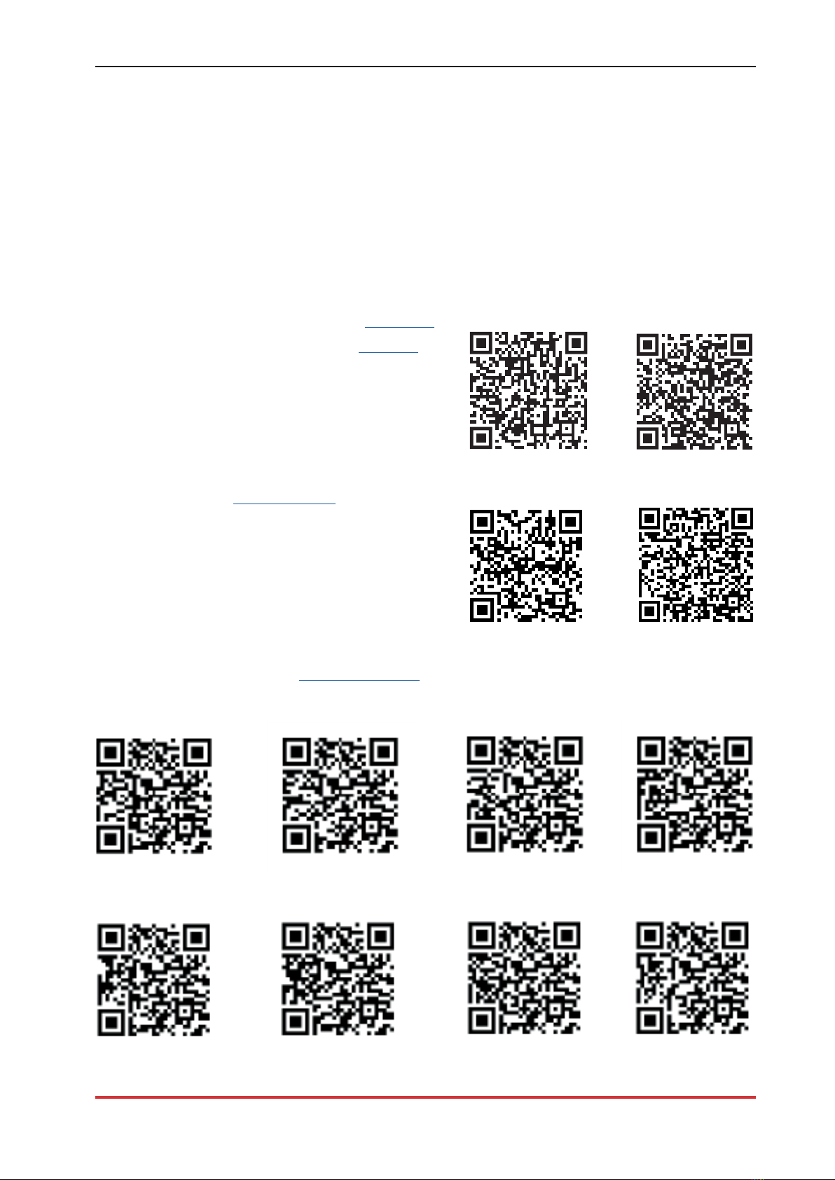
• Download the latest firmware version: Firmware. FIRMWARE MODBUS
• Download complete Modbus register: Modbus.
• Download the app: HERU IQ App APPLE GOOGLE
• Download wiring diagrams via the links below.
• Links to product information www.ostberg.com
HERU S
HERU 100 S EC HERU 160 S EC HERU 200 S EC HERU 300 S EC
HERU T
HERU 100 T EC HERU 160 T EC HERU 200 T EC HERU 300 T EC

1270447_3
EN | Table of Content
5
Table of Content
1 Safety........................................................................................................6
Warnings ...................................................................................................................................6
General safety...........................................................................................................................6
Product label .............................................................................................................................7
Declaration of conformity........................................................................................................8
2 Transport and storage .............................................................................9
General......................................................................................................................................9
Checking the delivery...............................................................................................................9
3 Installation..............................................................................................10
3.1 Mounting principles .........................................................................................................11
3.2 Mounting distance ...........................................................................................................12
3.3 Charging the wireless display .........................................................................................13
3.4 HERU S...............................................................................................................................13
3.4.1 Dismounting the unit to reduce the weight when installing HERU S..................................13
3.4.2 Installation HERU S ...........................................................................................................15
3.4.3 Moving the electric heater for flow in the opposite direction HERU S................................17
3.4.4 Mounting the parts after installing HERU S .......................................................................18
3.5 HERU T...............................................................................................................................19
3.5.1 Dismounting the unit to reduce the weight when installing HERU T. .................................19
3.5.2 Installation HERU T ...........................................................................................................21
3.5.3 Mounting the parts after installing HERU T .......................................................................25
3.6 Connecting the unit to the power source ......................................................................27
3.7 Connecting Modbus to external control equipment .....................................................28
4 Final routines..........................................................................................29
5 Commissioning.......................................................................................30
5.1 Starting the HERU unit for the first time........................................................................30
5.2 Configuring the unit.........................................................................................................31
5.3 Adapting the unit for airflow in the opposite direction ...............................................32
5.4 Configuring the unit for Modbus....................................................................................32
6 Technical data.........................................................................................33
7 Select Menu overview...........................................................................35
8 Control diagram .....................................................................................41
9 Connections main board .......................................................................42
10 Configuration protocol for HERU S and HERU T................................44

1270447_3
6
EN | Safety
1 Safety
1.1 Warnings
WARNING!
A warning states a risk of personal injury.
AKTAS!
A caution states a risk of damage to equipment.
1.2 General safety
WARNING!
All electrical installations must be performed by a qualified electrician.
WARNING!
Power must be cut to the unit for two minutes before work can be started.
WARNING!
Ensure that the power cable is not damaged during mounting and installation.
WARNING!
The unit may not be started until the installation is completely finished and the ducts have
been connected.
WARNING!
The safety switch must not be used for normal starting and stopping of the unit.
Use the accompanying wireless display.
WARNING!
The safety switch must be switched off when the cover of the electrical distribution box or
the doors/cover of the unit are opened/removed from the unit.
WARNING!
The unit must always be equipped with a type A or B, 30 mA residual current device (RCD).
Units without plugs must be installed with a safety switch, which must be mounted close by.
WARNING!
Units with plugs must be fused with a C10 A-fuse.
WARNING!
Units without plugs must be fused with a 2xC10 A-fuse together with 2.5 mm2conductor.
WARNING!
All operations on the unit and its peripheral equipment must be performed in accordance
with local laws and regulations.
WARNING!
Watch out for sharp edges and corners on the unit.

1270447_3
EN | Safety
7
WARNING!
Pay attention to the weight of the unit and its parts during mounting and maintenance.
WARNING!
Rotating, hot and electrical components can cause serious injuries.
WARNING!
Ducts must be connected and doors/cover must be closed be locked before starting up the
unit. Risk of personal injury from rotating parts.
CAUTION!
We recommend always installing a spring-return damper in the ducts for fresh air
and exhaust air.
CAUTION!
Do not connect an exhaust air type tumble dryer or drying cabinet to the system due to the
high air humidity.
CAUTION!
If the unit is installed when it is cold outside/in the winter and it will not immediately be
put into use, the ducts must be plugged again otherwise there is a risk of condensation and
the unit freezing.
1.3 Product label
Example of product label
1 Item number
2 Product name
3 Maximum power including heater
4 RPM at maximum power
5 Current at maximum power including heater
6 Serial number
7 Serial number as bar code
8 QR-code for product web page

1270447_3
8
EN | Safety
EU DECLARATION OF CONFORMITY
We hereby confirm that our products comply with the requirements in the following
EU-directives and harmonised standards and regulations.
Manufacturer: H. ÖSTBERG AB
Industrigatan 2
SE-774 35 Avesta, Sweden
Tel No +46 226 860 00
Fax No +46 226 860 05
http://www.ostberg.com
VAT No SE556301220101
Products: Heru S Next Generation, Heru T Next Generation
This EU declaration is applicable only if the installation is made in accordance with the enclosed installation instructions
and that the product has not been modified.
Low Voltage Directive (LVD) 2014/35/EU
Harmonised standards:
xEN 60335-1
xEN 60335-2-40
xEN 60335-2-30
Radio Equipment Directive (RED) 2014/53/EU
Harmonised standards:
xEN 300 220
Directive for Electromagnetic Compatibility (EMC) 2014/30/EU
Harmonised standards:
xEN 303 446-1 (EN 55014-1, EN 55014-2, EN 61000-3-2, EN 61000-3-3)
xEN 301 489-3
Machinery Directive (MD) 2006/42/EC
Harmonised standards:
xEN ISO 12100
xEN ISO 13857
xEN 60204-1
Ecodesign Directive 2009/125/EC
Harmonised regulation:
x1253/2014 Ecodesign requirements for ventilation units
x1254/2014 Energy labeling of residential ventilation units
RoHS Directive 2011/65/EU
Harmonised standards:
xEN 50581
Avesta 2019-10-15 Mikael Östberg
Technical development Manager

1270447_3
EN | Transport and storage
9
8WHOXIW
/XIWLQQWDN
)UHVKDLU
1270450_utg1_etikett_uteluft.indd 1 2019-05-20 07:51:51
7LOOXIW
7LOOXIW
6XSSO\DLU
1270453_utg1_etikett_tilluft.indd 1 2019-05-20 08:06:30
)UnQOXIW
$YWUHNNVOXIW
([WUDFWDLU
1270452_utg1_etikett_franluft.indd 1 2019-05-20 08:02:11
$YOXIW
$YNDVWOXIW
([KDXVWDLU
1270451_utg1_etikett_avluft.indd 1 2019-05-20 07:58:55
6SLVNnSD
.M¡NNHQKHWWH
&RRNHUKRRG
1270454_utg1_etikett_spiskapa.indd 1 2019-05-20 08:09:07
2016 1254/2014
HERU 200 S EC
42
dB 786 m³/h
2 Transport and storage
2.1 General
The HERU unit must be stored in a protected and dry space before installation.
2.2 Checking the delivery
1. Inspect the unit carefully upon delivery to check for any damage that may have occurred during
transport. Immediately inform the manufacturer in the event of severe damage.
NOTE! The manufacturer cannot be held liable for damage to the unit during transport, even if
the manufacturer has appointed the shipping agent.
2. Check that the delivery contains all ordered parts.
The following parts will be included in the HERU delivery:
• Mounted HERU unit
• Labels:
- Air direction labels - Energy label (example)
(only HERU T 100/160)
• Cables:
- Antenna cable
- GT7 cable (only for HERU S)
- Cord set with plug (excluding HERU S 200/300 and HERU T 200/300)
• 2 filters
• Touch display/Wireless display
• Wall console for the unit (only for HERU T 100/160)
• Wall console for the display
• Charger
• Vibration damper x2 (HERU T 100), x3 (HERU T 160)
• Antenna and antenna bracket
• Information sheet (only for HERU S)
• Installation manual
• Manual for operation and maintenance
3. Contact your dealer if anything is missing.

1270447_3
10
EN | Installation
3 Installation
WARNING!
Power must be cut to the unit for two minutes before work can be started.
WARNING!
Se till att elektriciteten är avstängd under hela monteringsprocessen.
WARNING!
The unit may not be started until the installation is completely finished and the ducts have been
connected.
WARNING!
All electrical installations must be performed by a qualified electrician.
WARNING!
The safety switch must be switched off when the cover of the electrical distribution box or the
doors/cover of the unit are opened/removed from the unit.
WARNING!
All operations on the unit and its peripheral equipment must be performed in accordance with
local laws and regulations.
WARNING!
Rotating, hot and electrical components can cause serious injuries.
CAUTION!
Do not connect an exhaust air type tumble dryer or drying cabinet to the system due to the
high air humidity.
CAUTION!
If the unit is installed when it is cold outside/in the winter and it will not immediately be put
into use, the ducts must be plugged again otherwise there is a risk of condensation and the unit
freezing.
CAUTION!
Installation and commissioning must be performed by a professional in order for the warranty
to apply

1270447_3
EN | Installation
11
3.1 Mounting principles
HERU S for placement in warm or cold space, e.g. in the attic.
HERU T for placement in warm space, e.g. in the laundry.
2
1 Intake grille for fresh air
2 Fresh air duct
3 HERU S energy recovery unit
4 Silencers
5 Supply air duct
6 Extract air duct
7 Exhaust air duct
8 Roof hood exhaust air
9 Wireless IQC display
1 Intake grille for fresh air
2 Fresh air duct
3 HERU T energy recovery unit
4 Silencers
5 Supply air duct
6 Extract air duct
7 Cooker hood extract air
8 Exhaust air duct
9 Roof hood exhaust air
10 Wireless IQC display
1
3445
6
7
8
9
2
1
3
4 4 5
6
8
9
710

1270447_3
12
EN | Installation
3.2 Mounting distance
Mounting distance for HERU S
(mm) A B C D E
HERU 100 S EC 415 850 969 507 51
HERU 160 S EC 519 1038 1131 574 51
HERU 200 S EC 728 1456 1250 680 51
HERU 300 S EC 728 1456 1250 680 51
Mounting distance for HERU T
(mm) A B C D E
HERU 100 T EC RE/LE 796 990 492 759 –
HERU 160 T EC RE/LE 942 1130 559 919 –
HERU 200 T EC RE/LE 1124 1344 682 1135 100
HERU 300 T EC RE/LE 1124 1344 682 1135 100

1270447_3
EN | Installation
13
3.3 Charging the wireless IQC display
Preparations :
No preparations are required.
1. Connect the charger’s mini USB connector to the wireless IQC display.
2. Connect the charger to the wall socket.
3.4 HERU S
3.4.1 Dismounting the unit to reduce the weight when installing HERU S.
Method for dismounting unit
1 Plastic cover
2 Screws
3 Unit lid
4 Quick connector for rotor cassette
5 Rotor cassette
6 Quick connector for fan
7 Screw Torx T25
8 Fan
Preparations:
Tool
• Torx T25 screwdriver
• Flat-blade screwdriver/13 mm socket
No preparations are required.
8
567
8
4 6 7
2
13

1270447_3
14
EN | Installation
Remove the lid of the unit.
1 Remove the plastic corner cover.
2 Unscrew the screws
holding the unit lid.
3 Lift off the lid.
Remove the rotor cassette.
4 Disconnect the rotor cassette’s quick connector.
5 Take out the rotor cassette.
Remove the fans.
6 Disconnect the fans’ quick connectors.
7 Remove the Torx T25 screw on the fans.
8 Take out the fans.
2
3
1
4
5
8
8
67

1270447_3
EN | Installation
15
3.4.2 Installation HERU S
CAUTION!
The cooker hood must not be connected to the unit due to the increased cleaning requirement.
Preparations:
• Place insulation board on the installation surface.
• The mounting distance, see 3.2 Mounting distance, must be followed.
• HERU S can be mounted in a cold or warm space.
• Local regulations for siting, access and electrical connections must be followed when installing HERU S.
• The dimensioned airflow should not exceed 75% of the unit’s maximum capacity.
• When installing in warm and moist places, for example a bathroom or utility room, condensation may occur
on the outside of the unit at low outdoor temperatures. If the unit is installed in cold weather and cannot
immediately be put into use, the ducts must be plugged again otherwise there is a risk of condensation.
• We recommend always installing a spring-return damper in ducts for fresh air and exhaust air.
• If there are major differences between ambient temperature and the temperature in the ducts for the supply
and extract air, these must be insulated to prevent condensation.
• The ducts for fresh air and exhaust air must always be insulated against condensation.
• The ducts must be insulated all the way up to the unit.
Tool
• Ø9 mm drill bit
• Spirit level
• Torx T25 screwdriver
Material - HERU 100 och 160 S
• Insulation board, minimum 50 mm.
• Cable ties
Material - golvstående HERU 200 och 300 S
• Insulation board, minimum 50 mm.
• Cable ties
• Floor stand (available as accessory )
• Pipe clip or flange with surrounding insulation
1. Installing HERU S with the lid upwards (A) or to the side (B).
WARNING!
Do not install the unit vertically or with the cover downwards due to the risk of injury.
NOTE! Ensure that there is space for service and maintenance around the unit.
See 3.2 Mounting distance.

1270447_3
16
EN | Installation
Floor standing HERU 100 and 160 S
1 Place the unit on a shock-resistant insulation board,
minimum 50 mm.
Ensure that the unit is level in both
the x and y axes. Use a spirit level.
NOTE!
The base for the unit must be level and stable.
Floor standing HERU 200 and 300 S with floor stand as accessory
2 Place the unit on a shock-resistant insulation board,
minimum 50 mm.
3 Mount the floor stand with accompanying screws
4 Ensure that the unit is level in both
the x and y axes. Use a spirit level.
Adjust the feet (pos 3) if required.
NOTE!
The base for the unit must be
level and stable.
The Novibra mat accessory can
be placed under the feet to
minimise vibrations from the
floor joists.
Connect the ducts to the unit.
2. Use a pipe clip or flange with surrounding insulation.
3. Mount the duct sensor GT7 in the supply air duct. See 9Control diagram.
- Prepare the duct. Drill a Ø9 mm hole; site it approx. 1000 mm after the unit,
cooling or heating coil.
- Pull the cable through the cable bushing.
- Mount the duct sensor in the drilled hole. The duct sensor must be placed centrally in the duct.
- Attach the duct sensor. Secure with a cable tie around the cable bushing
4. Attach the antenna in a suitable place on the side of the unit. Place the antenna as centrally as
possible to maximise the signal in the building. An extension cord is available as an accessory,
if required.
CAUTION!
The antenna must not be attahed against any metal surface or object, as this will block the signal
5. If a heating coil is connected, a spring-return damper
must be installed in the ducts for fresh air and
exhaust air. This reduces the risk of freezing when
the unit is not in use.
5 Connect the ducts to one of the external
ground points on the unit.
1
5
2
3
4
3

1270447_3
EN | Installation
17
3.4.3 Moving the electric heater for flow in the opposite direction
NOTE!
The unit is configured for airflow in the standard direction on delivery.
The electric heater must be moved if the airflow needs to be changed to the opposite direction.
Preparations:
Tool
• Torx T25 screwdriver
No preparations are required.
1 Disconnect the
quick connector.
2 Unscrew the screw.
3 Remove the heater from the partition.
4 Lift out the heater.
5 Move the heater to the opposite side
on the other partition. Ensure that the
bracket on the right side of the heater
is positioned in the console.
6 Secure the heater with the screw.
7 Connect the quick connector.
Move the heater’s power supply cable on the
control card according to the wiring diagram.
NOTE!
For more information on how to configure
the unit for opposite flow direction,
see 5.3 Adapting the unit for airflow in the opposite direction.
The duct connections in
opposite flow direction.
A Supply air
B Extract air
C Fresh air
D Exhaust air
Change the labels for flow direction on the HERU S unit to four new labels from the accessory
box. Place them according to the figure for opposite flow direction.
1
2
34
7
6
5
A
B
C
D

1270447_3
18
EN | Installation
3
2
1
1
4
5
7
8 9
3.4.4 Mounting the parts after installing HERU S
Preparations:
Tool
• Torx T25 screwdriver
No preparations are required.
Mount the fans.
1 Insert the fans.
2 Screw in the fans with
the Torx T25 screws.
3 Connect the fans’ quick connectors.
Mount the rotor cassette.
4 Insert the rotor cassette.
5 Connect the rotor cassette’s
quick connector.
Mount the lid.
7 Place the lid on the unit.
8 Tighten the screws clockwise.
9 Click in the four plastic corner covers.

1270447_3
EN | Installation
19
3.5 HERU T
3.5.1 Dismounting the unit to reduce the weight when installing HERU T
Method for dismounting unit
1 Upper and lower door screw
2 The unit’s doors
3 The rotor cassette’s quick connector
4 Rotor cassette
5 Torx T25 screw
6 Quick connector
7 Fans
Preparations:
Tool
• Torx T25 screwdriver
• Flat-blade screwdriver
• Hex key 4 mm with ball end
No preparations are required.

1270447_3
20
EN | Installation
5
8
8
4
7
6
7
6
1
1
2
3
3
Dismount the unit’s doors
1 Open the doors.
2 Unscrew the screws.
3 Hold the door and remove
the upper and lower screws.
Pull the door outwards to release it from the unit.
Remove the rotor cassette.
4 Remove the rotor cassette’s quick connector.
5 Pull out the rotor cassette.
Remove the fans.
6 Remove the quick connectors for the fans.
7 Unscrew the Torx T25 screws on the fans.
8 Pull out the fans.
This manual suits for next models
15
Table of contents
Languages:
Popular Test Equipment manuals by other brands

EXFO
EXFO FTB-610 user guide

System Sensor
System Sensor RTS151KEY Installation and maintenance instructions

MR CARTOOL
MR CARTOOL V310 user manual

LMF Clima
LMF Clima HPH series Installation, operation and maintenance manual

AlcoSense
AlcoSense Elite2 user manual

PEWA
PEWA AMPROBE digital operating instructions

Greenheck
Greenheck ERM-52 Installation, operation and maintenance manual

Kikkoman
Kikkoman Lumitester PD-30 instruction manual

HyQuest Solutions
HyQuest Solutions TB340A instruction manual

Rosenberger
Rosenberger RPC-2.92 user manual

TESTING
TESTING Vicat operating manual

Drummond
Drummond MTL10 instruction manual