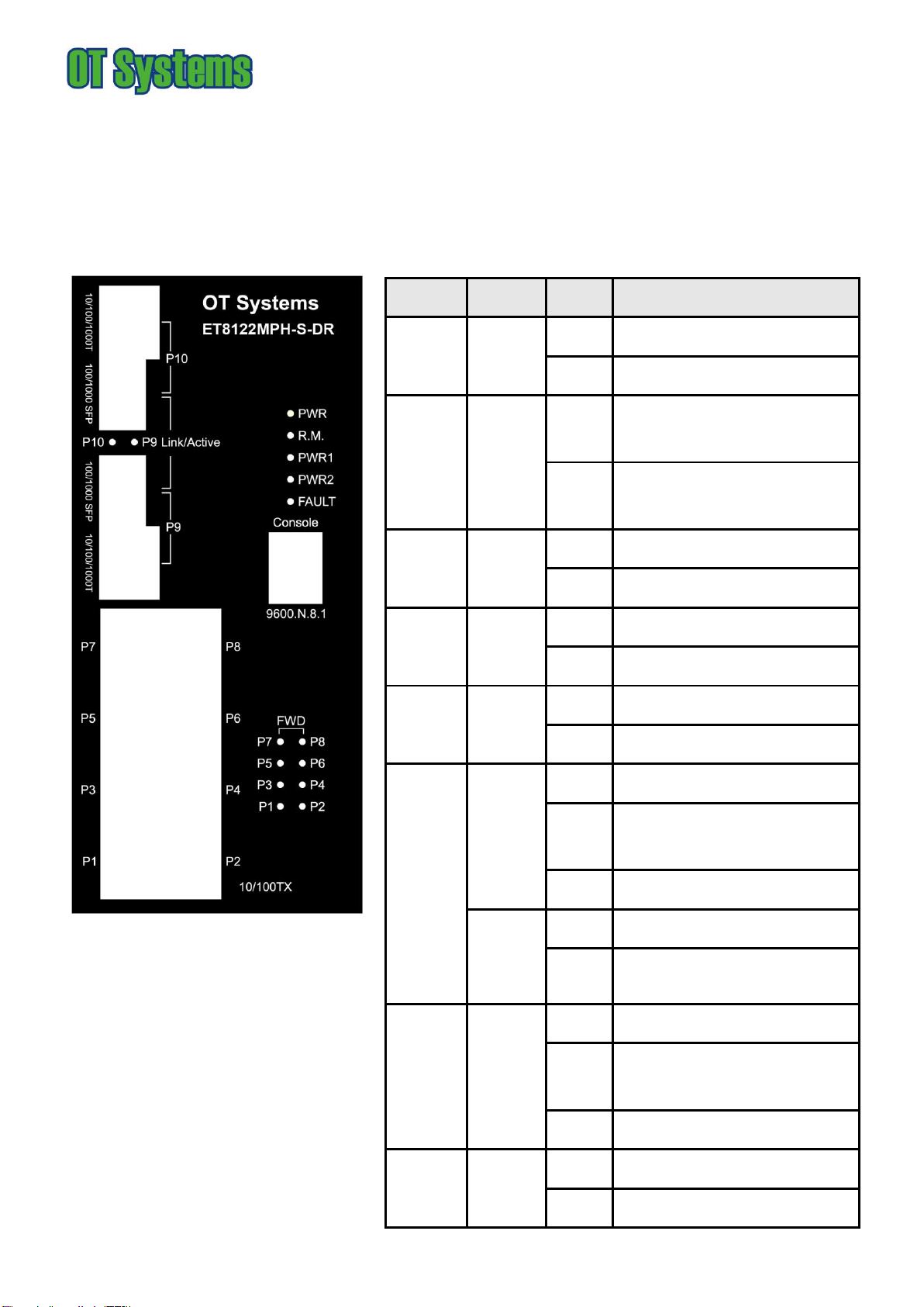
OT Systems ET8122MPH-S-DR User manual

ET8122MPH-S-DR
Hardened 8-port 10/100TX + 2-Port 10/100/1000T/100/1000 SFP Combo with 8 PoE Injectors
Industrial Ethernet Switch
1
This quick start guide describes how to install and use the hardened Ethernet Switch. Capable of operating at temperature extremes of -40°C to
+75°C, this is the switch of choice for harsh environments constrained by space.
Physical Description
The Terminal Block and Power inputs
The Terminal Block
PWR1
Power Input 1 (48VDC)
GND
Power Ground
PWR2
Power Input 2 (48VDC)
GND
Power Ground
Earth Ground
FAULT
The relay opens if PWR1 or PWR2 fails (1A)
DC Terminal Block Power Inputs: There are two pairs of power inputs can be used to power up this media converter. Redundant power supplies
function is supported. You only need to have one power input connected to run the Switch.
The 10/100Base-TX and Mini-GBIC combo port
The 10/100Base-TX Connections
The following lists the pinouts of 10/100Base-TX ports.
Pin
Regular Ports
Uplink port
1
Output Transmit Data +
Input Receive Data +
2
Output Transmit Data -
Input Receive Data -
3
Input Receive Data +
Output Transmit Data +
4
NC
NC
5
NC
NC
6
Input Receive Data -
Output Transmit Data -
7
NC
NC
8
NC
NC

ET8122MPH-S-DR
Hardened 8-port 10/100TX + 2-Port 10/100/1000T/100/1000 SFP Combo with 8 PoE Injectors
Industrial Ethernet Switch
2
Mini-GBIC combo port:
2 auto-detect Giga port—UTP or fiber. The gigabit Ethernet ports are hared with the mini-GBIC ports. UTP (Gigabit Ethernet) ports can
operate in half/full-duplex modes and work at speeds of 10/100/1000Mbps that support auto-sensing technology to enable each port to detect
the connecting speed. The mini-GBIC port is a joint for a mini-GBIC (SFP) transceiver, so the switch can be uplinked through fiber to another
one.
Use four twisted-pair, Category 5e or above cabling for RJ-45 port connection. The cable between the switch and the link partner (switch,
hub, workstation, etc.) must be less than 100 meters (328 ft.) long.
Use the mini-GBIC ports to uplink to another switch by inserting the mini-GBIC (SFP) transceiver.

ET8122MPH-S-DR
Hardened 8-port 10/100TX + 2-Port 10/100/1000T/100/1000 SFP Combo with 8 PoE Injectors
Industrial Ethernet Switch
3
Connecting to the Console Port
The supplied cable which one end is RS-232 connector and the other end is RJ-45 connector. Attach the end of RS-232 connector to PC or
terminal and the other end of RJ-45 connector to the console port of the switch. The connected terminal or PC must support the terminal
emulation program.
Pin Assignment
DB9 Connector
RJ-45 Connector
NC
1 Orange/White
2
2 Orange
3
3 Green/White
NC
4 Blue
5
5 Blue/White
NC
6 Green
NC
7 Brown/White
NC
8 Brown

ET8122MPH-S-DR
Hardened 8-port 10/100TX + 2-Port 10/100/1000T/100/1000 SFP Combo with 8 PoE Injectors
Industrial Ethernet Switch
4
Login in the Console Interface
When the connection between Switch and PC is ready, turn on the PC and run a terminal emulation program or Hyper Terminal and
configure its communication parameters to match the following default characteristics of the console port:
Baud Rate: 9600 bps
Data Bits: 8
Parity: none
Stop Bit: 1
Flow control: None
The settings of communication parameters
Having finished the parameter settings, click ‘OK’. When the blank screen shows up, press Enter key to have the
login prompt appears. Key in ‘root’(default value) for both User name and Password (use Enter key to switch),
then press Enter and the Main Menu of console management appears. Please see below figure for login screen.
Console login interface

ET8122MPH-S-DR
Hardened 8-port 10/100TX + 2-Port 10/100/1000T/100/1000 SFP Combo with 8 PoE Injectors
Industrial Ethernet Switch
5
The Port Status LEDs, Wall Mounting Kit
LED Indicators
The diagnostic LEDs located on the front panel of the industrial switch provide real-time information of system and optional status. The following
table provides the description of the LED status and their meanings for the switch.
LED
Color
Status
Meaning
PWR
Green
On
The switch unit is power on
Off
No power
R.M.
Green
On
The industrial switch is the master of
X-Ring group
Off
The industrial switch is not a ring master
in X-Ring group
PWR1
Green
On
Power 1 is active
Off
Power 1 is inactive
PWR2
Green
On
Power 2 is active
Off
Power 2 is inactive
FAULT
Red
On
Power or port failure
Off
No failure
P9, P10
(RJ-45)
Green
(Upper
LED)
On
A network device is detected.
Blinking
The port is transmitting or receiving
packets from the TX device.
Off
No device attached
Green
(Lower
LED)
On
1000M
Off
10/100M
Link/Activ
e (P9, P10
SFP)
Green
On
The SFP port is linking
Blinks
The port is transmitting or receiving
packets from the TX device.
Off
No device attached
P1 ~ P8
Green
On
A network device is detected.
Blinking
The port is transmitting or receiving

ET8122MPH-S-DR
Hardened 8-port 10/100TX + 2-Port 10/100/1000T/100/1000 SFP Combo with 8 PoE Injectors
Industrial Ethernet Switch
6
packets from the TX device.
Off
No device attached
Amber
On
The port is operating in full-duplex mode.
Blinking
Collision of Packets occurs.
Off
The port is in half-duplex mode or no
device is attached.
FWD (P1 ~
P8)
Green
Green
A powered device is connected utilizing
Power over Ethernet on the port
Off
No device is connected or power
forwarding fails

ET8122MPH-S-DR
Hardened 8-port 10/100TX + 2-Port 10/100/1000T/100/1000 SFP Combo with 8 PoE Injectors
Industrial Ethernet Switch
7
DIN-Rail Mounting
The DIN-Rail is screwed on the industrial switch when out of factory. If the DIN-Rail is not screwed on the industrial switch, please see the
following pictures to screw the DIN-Rail on the switch. Follow the steps below to hang the industrial switch.
1. First, insert the top of DIN-Rail into the track.
2. Then, lightly push the DIN-Rail into the track.
3. Check if the DIN-Rail is tightened on the track or not.
4. To remove the industrial switch from the track, reverse steps above.

ET8122MPH-S-DR
Hardened 8-port 10/100TX + 2-Port 10/100/1000T/100/1000 SFP Combo with 8 PoE Injectors
Industrial Ethernet Switch
8
Wall Mount Plate Mounting
Follow the steps below to mount the industrial switch with wall mount plate.
1. Remove the DIN-Rail from the industrial switch; loose the screws to remove the DIN-Rail.
2. Place the wall mount plate on the rear panel of the industrial switch.
3. Use the screws to screw the wall mount plate on the industrial switch.
4. Use the hook holes at the corners of the wall mount plate to hang the industrial switch on the wall.
5. To remove the wall mount plate, reverse steps above.

ET8122MPH-S-DR
Hardened 8-port 10/100TX + 2-Port 10/100/1000T/100/1000 SFP Combo with 8 PoE Injectors
Industrial Ethernet Switch
9
Functional Description
Meets IEC61000-6-2 EMC Generic Standard Immunity for industrial environment.
Support 802.3/802.3u/802.3ab/802.3z/802.3x/802.3af.
Auto-negotiation: 10/100/1000Mbps, Full/half-duplex; Auto MDI/MDIX.
SFP (Mini-GBIC) supports 100/1000 Dual Mode
Support 8K MAC addresses. Provides 1M bits memory buffer.
Alarms for power failure by relay output.
Operating voltage and Max. current consumption: 1.1A @ 12VDC, 0.55A @ 24VDC. Power consumption: 13.2W Max.
Power Supply: Redundant DC Terminal Block power inputs or 12VDC DC JACK with 100-240VAC external power supply.
Operating temperature ranges from -40°C to +75°C.
Supports Wall Mounting installation; Optional DIN-Rail mounting kit.
Assembly, Startup, and Dismantling
Wall Mounting Kit installation
Assembly: Securely fasten the wall-mount kits to the bottom of module by using the provided screws (6 pcs)
Mount the standalone unit onto a fixture, e.g. a plank, (either on the wall or on a flat surface) with at least 2 screws piercing
through the holes on the mounting frame to secure it in position.
Startup: Connect the supply voltage to start up the Media Converter via the terminal block.
Dismantling: Locate and remove the securing screws. Usually, but not limited to, at least 2 screws.
DIN rail installation (Optional)
Assembly: Place the Media Converter on the DIN rail from above using the slot. Push the front of the Media Converter
toward the mounting surface until it audibly snaps into place.
Startup: Connect the supply voltage to start up the Media Converter via the terminal block.
Dismantling: Pull out the lower edge and then remove the Media Converter from the DIN rail.
Manual Earth Green manual is available in our website. www.ot-systems.com
Table of contents
Other OT Systems Switch manuals
Popular Switch manuals by other brands

A10
A10 Thunder series 930 installation guide

Pentair
Pentair Pentek Intellidrive quick start guide

Cabletron Systems
Cabletron Systems MMAC-Plus 9E312-12 Appendix

Buffalo
Buffalo BS-GS20 Series user manual

Hubbell
Hubbell Euclid PBP Pendant Assembly & parts list

NETGEAR
NETGEAR S350 Series Hardware installation guide

Cisco
Cisco 3750 - Catalyst EMI Switch datasheet

Rose electronics
Rose electronics Vista DVI Plus Installation and operation manual

Endress+Hauser
Endress+Hauser Liquiphant FTL62 operating instructions

Avocent
Avocent DSR Series DSR1031 release note

Orei
Orei BK-21A user manual

KTI Networks
KTI Networks KGS-2416 user manual