OTARI MX-5050BII Series User manual


Other manuals for MX-5050BII Series
1
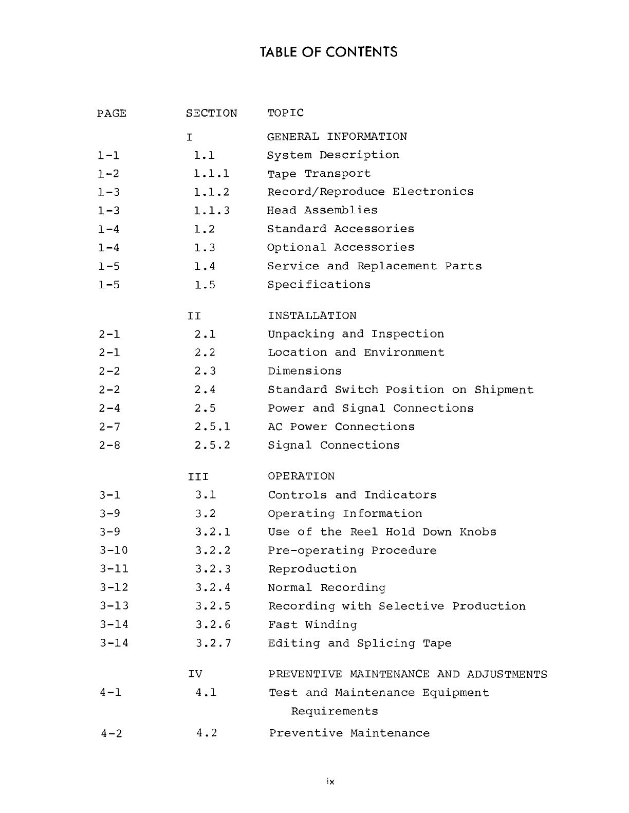
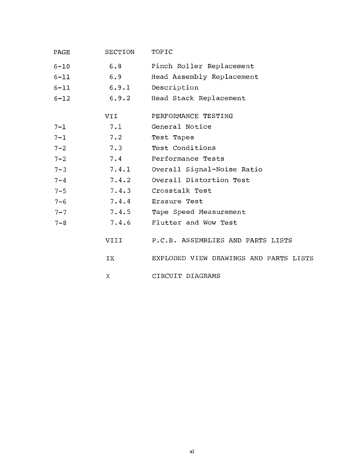
Table of contents
Other OTARI Recording Equipment manuals

OTARI
OTARI MX-505MKIII-2 User manual

OTARI
OTARI MX-50II Series User manual

OTARI
OTARI MX 5050 BQII Series User manual

OTARI
OTARI MTR-90III User manual

OTARI
OTARI MX-55T-M User manual

OTARI
OTARI MX-5050 User manual

OTARI
OTARI MTR-10II Series User manual

OTARI
OTARI RADAR User manual

OTARI
OTARI MX-5050BII Series User manual

OTARI
OTARI MX-505MKIV-2 Manual


Popular Recording Equipment manuals by other brands

Sound Devices
Sound Devices 788T User guide and technical information

Interlogix
Interlogix Kalatel KA2 ProBridge Series Product Overview & Installation Manual

VoiceCollect
VoiceCollect IR44CF-II Battery changing instructions

Megatron
Megatron ETA25PS Programming manual

Nav TV
Nav TV W213-N RVC quick reference

Citronic
Citronic DSM48 user manual

ADJ
ADJ American Audio XEQ-152B instruction manual

BLACK NOISE
BLACK NOISE Dual Rectifier II - S user manual

Peavey
Peavey Digital Effects Processor user guide

Wheatstone
Wheatstone E-Series Technical documentation

Zoom
Zoom G7.1ut Operation manual

Velleman
Velleman USB INTERFACE KIT FOR ROBOTIC ARM Assembly and instruction manual


