OTARI MX-55T-M User manual

Parts
No.
OS3-207
[fJOSCJH
MX-55T-M,
T,
N-M
PROFESSIONAL
RECORDERS
OPERATION
AND
MAINTENANCE
MANUAL
SIXTH
EDITION
Printed
:
May
1990
Ed
.6
(GK)
Otari,
Inc.
Copyright
©
1989,
1990
Otari,
Inc.
Printed
in
Japan
This
manual
may
not
be
reproduced
by
any
means
without
written
permission
.

CAUTION
To
prevent
fire
or
shock
hazard:
Do
not
expose
this
unit
to
rain
or
moisture.
Do
not
remove
panels
(unless
instructed
to
do
so).
There
are
no
user-serviceable
parts
inside.
Refer
servicing
to
qualified
service
personnel.
PLEASE
READ
THROUGH
THE
SAFETY
INSTRUCTIONS
ON
THE
NEXT
PAGE.


1.
Read
Instructions
2.
Retain
Instructions
3.
Heed
Warnings
4.
Follow
Instructions
5.
Water
and
Moisture
6.
Carts
and
Stands
7.
Ventilation
8.
Heat
9.
Power
Sources
1
D.
Grounding
or
Polarization
11
.
Power
Cord
Protection
SAFETY
INSTRUCTIONS
All
the
safety
and
operating
instructions
should
be
read
before
the
device
is
operated.
The
safety
and
operating
instructions
should
be
retained
for
future
.
All
warnings
on
the
device
and
in
the
operating
instructions
should
be
adhered
to.
All
operating
and
use
instructions
should
be
followed.
The
device
should
not
be
used
near
water
-
for
example,
near
bathtub,
wash
bowl,
kitchen
sink
,
laundry
tub,
in
a
wet
basement,
or
near
a
swimming
pool,
etc
.
The
device
should
be
used
only
with
a
cart
or
stand
that
is
recommended
by
the
manufacturer.
The
device
should
be
situated
so
that
its
location
or
position
does
not
interfere
with
its
proper
ventilation
.
For
example,
the
device
should
not
be
situated
on
a
bed,
sofa,
rug,
or
similar
surface
that
may
block
the
ventilation
openings;
or,
placed
in
a
built-in
installation,
such
as
a
bookcase
or
cabinet
that
may
impede
the
flow
of
air
through
the
ventilation
openings.
The
device
should
be
situated
away
from
heat
sources
such
as
radiator
,
heat
registers,
stoves
or
other
appliances
(including
amplifiers)
that
produce
heat.
The
device
should
be
connected
to
a
power
supply
only
of
the
type
described
in
the
operating
instructions
or
as
marked
on
the
device.
Precautions
should
be
taken
so
that
the
grounding
or
polarization
means
of
the
device
is
not
defeated.
Power
supply
cords
should
be
routed
as
they
are
not
likely
to
be
walked
on
or
pinched
by
items
placed
upon
or
against
them,
paying
particular
attention
to
cords
at
plugs,
convenience
receptacles,
and
the
point
where
they
exit
from
the
device.
iii
12.
Cleaning
The
device
should
be
cleaned
oll
'
ly
as
recommended
by
the
13.
Non-Use
Periods
14
Object
and
Liquid
Entry
15.
Damage
Requiring
Service
16.
Servicing
man
ufactu
rer.
The
power
cord
of
the
device
should
be
unplugged
from
the
outlet
when
left
unused
for
a
long
period
of
time.
Care
should
be
taken
so
that
objects
do
not
fall
and
i
that
liquids
are
not
spilled
,
into
the
enclosure
through
openings.
The
device
should
be
serviced
by
qualified
service
personnel
when:
A.
The
power-supply
cor
,d
or
the
plug
has
been
damaged;
or
B.
Objects
have
fallen,
or
liquid
has
been
spillled
'
into
the
appliance;
or
C.
The
appliance
has
been
exposed
to
r
ain;
or
D.
The
appliance
does
not
appear
to
operate
nor
m
ally
or
exhibits
marked
change
in
performance;
or
E.
The
appliance
has
been
dropped,
or
the
enclosure
damaged.
The
user
should
not
attempt
to
service
the
device
beyond
that
described
in
the
operating
instructions.
All
ot
l
her
serv
,
ice
should
be
referred
to
qualified
personnel.
iv
WARNING
This
equipment
generates,
uses
and
can
radiate
radio
frequency
energy
and
if
not
installed
and
used
in
accordance
with
the
instructions
manual,
may
cause
interference
to
radio
communications.
It
has
been
tested
and
found
to
comply
with
the
limits
for
a
Class
A
computing
device
pursuant
to
Subpart
J
of
Part
15
of
FCC
Rules,
which
are
designed
to
provide
reasonable
protection
against
such
interference
when
operated
in
a
commercial
environment.
Operation
of
this
equipment
in
a
residential
area
is
likely
to
cause
interference
in
which
case
the
user
at
this
own
expense
will
be
required
to
take
whatever
measures
may
be
required
to
correct
the
interference.
v


COMMUNICATION
WITH
OTARI
FOR
SERVICE
INFORMATION
AND
PARTS
The
Otari
products
are
manufactured
under
strict
quality
control
and
each
unit
is
carefully
inspected
and
tested
prior
to
shipment.
If,
however,
some
adjustment
or
technical
support
becomes
necessary,
replacement
parts
are
required,
or
technical
questions
arise,
please
contact
your
nearest
Otaril
dealer
or
contact
Otari
at:
Otarl,
Inc.
4-33-3
Kokuryo-cho
Chofu-shi,
Toky0182
Japan
Phone
:
(0424)
81-8626
Telex
:
J26604
OTRDENKI
Fax
:
(0424)
81-8633
Cable
:
OTARIDENKI
TOKYO
Otarl
Deutschland
GmbH.
Rudolf-Diesel-Str.12
D-4005
Meerbusch
2
(Osterath)
F.
R.
Germany
Phone
:
(02159)
50861
Telex
:
8531638
OTEl
D
Fax
:(02159)1778
Otari
(U.
K.)
Lt
d.
22
Church
Street
Slough
Berkshire
Sl1
1
PT
United
Kingdom
Phone:
(0753)822381
Telex
:
849453
OTAR
IG
Fax:
(0753)823707
Otarl
Corporation
378
Vintage
Park
Drive
Foster
City
California
94404
USA
Phone
:
(415)
341-5900
Telex
:
650
302
8432
MCI
UW
Fax
:
(415)
341-7200
Otari
Singapore
Pte.,
Ltd.
625
Aljunied
Road
#07-05
Aljunied
Industrial
Complex
Singapore
1438
Phone
:
(743)
7711
Telex
:
RS
36935
OTARI
Fax:
(743)
6430
Another
part
of
Otari's
continuing
technical
support
program
for
our
products
is
the
continuous
revision
of
manuals
as
the
equipment
is
improved
or
modified.
In
order
for
you
to
receive
the
information
and
support
which
is
applicable
to
your
equipment,
and
for
the
technical
support
program
to
function
properly,
please
include
the
following
information,
most
of
which
can
be
obtained
from
the
Serial
number
label
on
the
machine,
in
all
correspondence
with
Otari:
•
Model
Number:
•
Serial
Number:
•
Date
of
Purchase:
•
Name
and
address
of
the
dealer
where
the
machine
was
purchased
and
the
power
requirements
(voltage
and
frequency)
of
the
machine.
vii

MX-55
Operation
and
Maintenance
Manual
Table
of
Contents
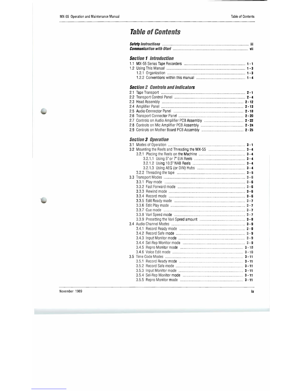
Ta
ble
Df
CDntents
Safety
Instruc
t/on
s
...
..
.
....
..
..
......
.
..
.
...
.............
.
.......
........
..
..
.
..
.
...................................
iii
Communi
cat
ion
with
Otarl
..
......
......
...
..
....
..
............
...
.......
...
..
.
.....
...........
.....
...
..
.
......
vII
Sec
tion
1
Introduction
1.1
MX
-5
5
Seri
es
Tape
Rec
orders
.......................
..
...........
.
.................................
1
·1
1.2
U
sin
gT
his
Manua
l
........
...
..............................
..
.......
..
.........
.......
....
....
......
......
..
1
·3
1.2.1
Orga
ni
zation
..
......
......
..
.
.....
..
.....
...
......
........
......
..
........
.....
..
.........
....
.......
1
·3
1
.2.2
Con
vention
sw
ithin
t
his
manual
.....
.........
......
....
...............
....
......
..
....
. 1
·4
Sec
tion2
Controls
and
Indicato
rs
2.1
Tap
eT
ra
n
sport
....
......
........
....................
..
....................
.
................
...
................
2·1
2.2
T
ransport
Con
t
ro
l
Panel
.......
..
....
...
..
...............
......
..
..........
..
....
..
.
........
..
...........
2·4
2.3
He
ad
Assembly
......
.....
....
.
.....
..
.
....
..
.....
....
....
......
....
.........
...
.................
....
.......
2
·12
2.4
Amp
li
f
ier
Pane
l
..
....
.......
....
..........
.
....
...
....
.....
...
......
..
......
..
................
..
.......
......
2
·13
2.5
Au
d
io
Co
nne
cto
r
Pan
el
....
.
..
..
........
...
..
.
.............
...
............
.
...........
..
...............
2
·18
2.6 T
ransport
Connec
tor
Pane
l .
.......
...
......
.......
.......
...
.....
....
......
....
...................
.
2·20
2.7
Controls
on
Audio
Am
plifier
PC
B
Assembly
.........
..
.......
..
............
.
..
.
.....
....
2·22
2.8
Contro
ls
on
MicA
mp
li
fier
PCB
As
sembly
..
..............
......
..........
..
...............
2·24
2.9
Con
tro
ls
on
Mother
Boa
rd
P
CB
Ass
embly
....
.
..
.....
..
.
..
....
..............
.
......
..
....
2·25
Section
3
Operation
3.1
M
odes
of
Operation
..
...
..
....
......
.......
...
....
.....................
....
.....
....
......
....
............
.
3·1
3.2 M
ou
nti
ng
the
R
ee
ls
an
dThrea
ding
the
MX-55
.
......
..
.
......
........
.....
.............
3·4
3.
2.1
Pl
acing
the
Ree
lson
the
Machine
.....................................................
3·4
3.2
.
1.
1
Us
i
ng
5"
or
7"
EIA
R
eels
........
......
.....
.
..........
..
..........................
3·4
3
.2.1
.2
Usi
ng
10.5
"
NAB
Reels
............
...
.
......
..
....
..
....
...
..
......
...
....
..
.
...
..
3·4
3.2.
1.
3
Using
AEG
(or
DIN
)
Hub
s
..
......
..
...........
.......
..
....
........
...
..........
3·4
3.2
.2
Threading
the
tape
.......
..
..
....
.....
......
..
.........
....
.................
..
...........
....
...
3·5
3.3
Tra
n
sport
Modes
..
....
......
.....
....
.....
......
....
..
..
.
..
.
..
.
..
......................
.....
.......
...
....
..
3·6
3.3.1
Pl
ay
mode
...
..................
.
.....
.
..
...
.
..
.....
....
.....................
.
.................
....
....
3·
6
3.3
.2
Fast
Forwa
rd
mode
..
....
......
..........
...................................
........
....
........
3·
6
3
.3
.3 R
ewind
mode
........
......
........
...
..
..
...
..
...
......
....
......
..
.....
.
..
....
......
.....
..
.
....
..
3·6
3.
3.4
R
ecord
mode
..
.....
......
....
.....
.
...
..
..........
.....
.....
.
..........
.
..........................
3·6
3.3.5
Ed
it
R
eady
mode
....
..
...............................
..
..
..
.
................
.....
..
....
..
.......
3
·7
3.3.6
Edit
Pl
ay
mo
de
...............
......
..
........................................
.....
......
..
.....
.
...
3·
7
3.3
.7
Cue
mode
..
...........
.
..........
..
..........
..
.
.........................................
.
..........
3·
7
3.
3.8
Vari
Speed
mo
de
...........
..
...
...
....
.......
.. ..
.
..
............
...
................
........
....
. 3 · 7
3.
3.9
Presett
ing
th
e
Vari
S
peed
amount
........
.
..
.....
..
...
.......
.
...
........
...........
3·8
3.4
Aud
io
Channel
Modes
...........
....
......
.
.................................................
...
..
....
...
3·9
3
.4.
1 R
ecord
Ready
mode
..
.
..
..
..
.....
..
....
....
..
....
.....
....
.....
.......
...
.............
..
......
3 · 9
3
.4
.2
Record
Safe
m
ode
...............................................................................
3-9
3.4.3
Inpu
t
Monitor
mo
de
...
......
....
..
.
...
..
...
..
..
...
....
......
..
................................
3·9
3.4.4
Sel
·
Rep
Monitor
mode
..
.............
....
..
.
................
.
....
....
.
...
.......
..
.
....
.... 3-9
3.4
.5
Repro
Mo
nit
or
mod
e
..
........
.
....
.
.............................
.
..
.............
.......
. 3-10
3
.4.
6
Vo
i
ce
Edit
mode
..
...........
.
.............
..
.....
....
......
...
..
............
......
...
......
. 3-
10
3.5
Time
Code
Modes
.......
....
..
..
........
.
..
.
..
.
......
....
.....
...
..
...........
..
....
......
.....
...
3-11
3.5
.1
Record
R
eady
mo
de
.......
......
...
.
.........
..
......
..
.
.....
....
.....
...
....
3-
11
3.5
.2
Record
Safe
mod
e .
.........
..
.........
....
..
..
.
......
.......
.......
..
......
.....
....
.........
3-11
3.
5.3
Input
Mon
ito
r
mode
..
..
...........
....
......
...
..........
..
..
..
..
..
.....
....
.......
..
.. 3-11
3
.5.4
Sel
·
Rep
Mon
ito
r
mode
..
......
..
.
..
.
......................................................
3-11
3.5.5 R
epro
Mo
ni
tor
m
ode
....
...
.
.......
........
..
...
............................
...
......... 3·11
November
1989
Ix
x
Table
of
Contents
MX-55
Operation
and
Maintenance
Manual
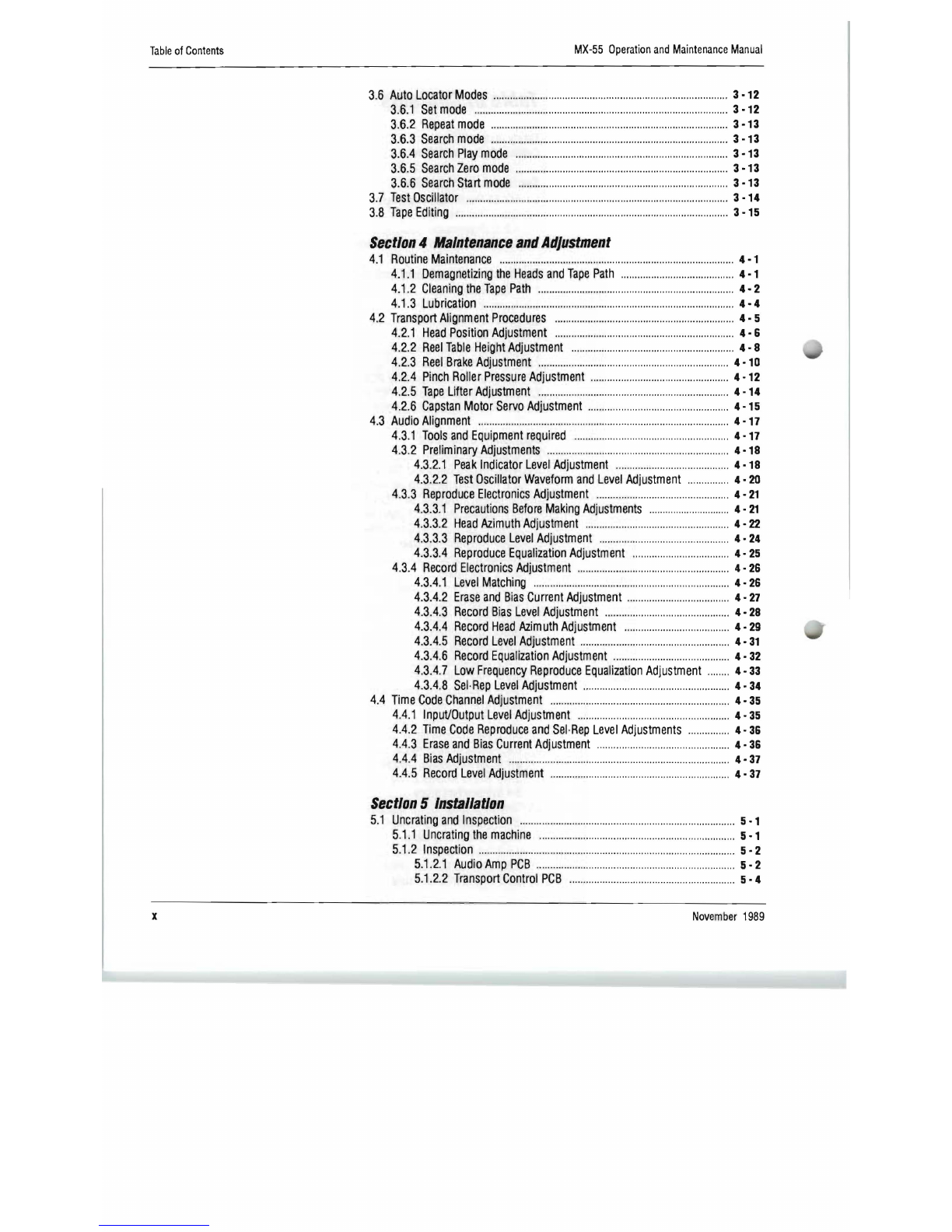
3.6
Auto
Locator
Modes
..
.
....
..
........
..
...
..
.
...
...
.
.....
..
...........
.
...
.
...
..
..
........
..
..
...........
3
·12
3.
6.1
Set
mode
............................................................................................
3
·12
3.
6.2
Repeat
mode
......................
....
........
.......
....
..
......
......
......
..
....
......
....
.....
3
·13
3.
6.3
Search
mode
..............
....
......
..
..........
.
..........
....
..
......
.......
............
....
....
3
·13
3.6.4
Search
Play
mode
....................
..
..........
....
......
....
..................
......
......
. 3
·13
3.6.5
Search
Zero
mode
........
....
.................................................................
3
·13
3.6
.6
Search
Start
mode
............
........
........
..
....
..........
..........
........
....
..........
3
·13
3.7
Test
Oscillator
..
....
..........
....
......
....
............
......
............
..
................................
. 3
·14
3.8
Tape
Editing
...................................................................................................
3
·15
Section
4
Maintenance
and
Adjustment
4.1
Routine
Maintenance
..
....
..........
..
..
........
......
............
....
....
........
......
......
........
...
4·1
4.1
.1
Demagnetizing
the
Heads
and
Tape
Path
..........
............
.......
............
4·1
4.1.2
Cleaning
the
Tape
Path
......
............................
..
..........
........
............
..
...
4·2
4.1.3
Lubrication
......
........
....
............
..
..............
............
..
..
..
...........................
4·4
4.2
Transport
Alignment
Procedures
...........................................................
......
4·5
4.2.1
Head
Position
Adjustment
....
....
.....................
....
..
..........
.....
......
......
..
.
4·
&
4.
2.2
Reel
Table
Height
Adjustment
....
..
....
....
.
........
....
...........
.
..
......
...
.........
4·8
4.2.3
Reel
Brake
Adjustment
............
..
..............
.
....
..
......
.
....
..
............
......
...
4
·10
4.2.4
Pinch
Roiler
Pressure
Adjustment
....
....
........
....
..................
..
..........
4
·12
4.2.5
Tape
Lifter
Adjustment
............
......
..........
..
................
....
..........
....
.....
4
·14
4.2.6
Capstan
Motor
Servo
Adjustment
..........
........
..........
......
......
.......
....
4
·15
4.3
Audio
Alignment
....
................
..
..............................................
..
.....................
4·
17
4.3.1
Tools
and
Equipment
required
..
..
.......................
..
.......
........
........
....
4·17
4.3.2
Preliminary
Adjustments
............
..
..
..
..........
....
........
.......
............
..
.....
4
·18
4.3.
2.1
Peak
Indicator
Level
Adjustment
........
............
........
......
......
. 4
·18
4.3.2.2
Test
Oscillator
Waveform
and
Level
Adjustment
........
....
...
4·20
4.3.3
Reproduce
Electronics
Adjustment
..........
..
........
..
..........
....
..
..........
4·21
4.3.3.1
Precautions
Before
Making
Adjustments
......
..............
......
..
..
4·21
4.3
.
3.2
Head
Azimuth
Adjustment
........
..
..............
..
....
..........
....
........
4·22
4.3.3.3
Reproduce
Level
Adjustment
..........
..
........
......
....
....
............
.
4·24
4.3
.
3.4
Reproduce
Equalization
Adjustment
...
..........
.........
..........
...
4·25
4.3.4
Record
,
Electronics
Adjustment
....................................
..
................
.
4·26
4.3
.
4.1
Level
Matching
..
......
........
....
....
......
..
..
...........
..
........
..
..............
4·26
4.3.4.2
Erase
and
Bias
Current
Adjustment
..
..
..............
....
.............
..
4·27
4.3.
4.3
Record
Bias
Level
Adjustment
....
.........................................
4·28
4.3.4.4
Recor
·d
Head
Azimuth
Adjustment
.....
....
..
.......
..
....
...
......
.....
4·29
4.3.4.5
Record
Level
Adjustment
........
.
..
....
............
.....
...........
.........
..
4·31
4.3.4.6
Record
Equalization
Adjustment
...........
..
............
..
...............
4·
32
4.3.4.7
Low
Frequency
Reproduce
Equalization
Adjustment
........
4·33
4.3.4.8
Sel·Rep
Level
Adjustment
......
......
.......
....
....
....
........
..
............
4·34
4.4
Time
Code
Channel
Adjustment
.........
..
............
......
........
......
....
.......
.....
..
.
...
4·35
4.4.1
Input/Output
Level
Adjustment
........................................
...
.........
.
..
4·35
4.4.2
Time
Code
Reproduce
and
Sel
·
Rep
Level
Adjustments
....
......
....
. 4·3&
4.4.3
Erase
and
Bias
Current
Adjustment
.................
....
.......
..
..................
4·36
4.4.4
Bias
Adjustment
...........................................
..
............
....
..
....
......
.......
4·37
4.4.5
Record
Level
Adjustment
.......................
.
..............................
.
..........
4·37
Section
5
Installation
5.1
Uncrating
and
Inspection
........
..
............
..
....
.
........
....
.............
..
......................
5·1
5.1.1
Uncratingthemachine
........
....
..........................
......
..........
.....
............
5·1
5.1
.2
Inspection
....
..............
..
....
......
,
.......
..
..........................
.............
.....
......
...
5·2
5.1.
2.1
Audio
Amp
PCB
..........
..
.
....
.......
....
....
..
.........
....
..
.
.......
.....
..........
5·2
5.1
.
2.2
Transport
Control
PCB
....
......
.................
...
.........
..
...................
5·4
November
1989
MX-55
Operation
and
Maintenance
Manual
Table
of
Contents
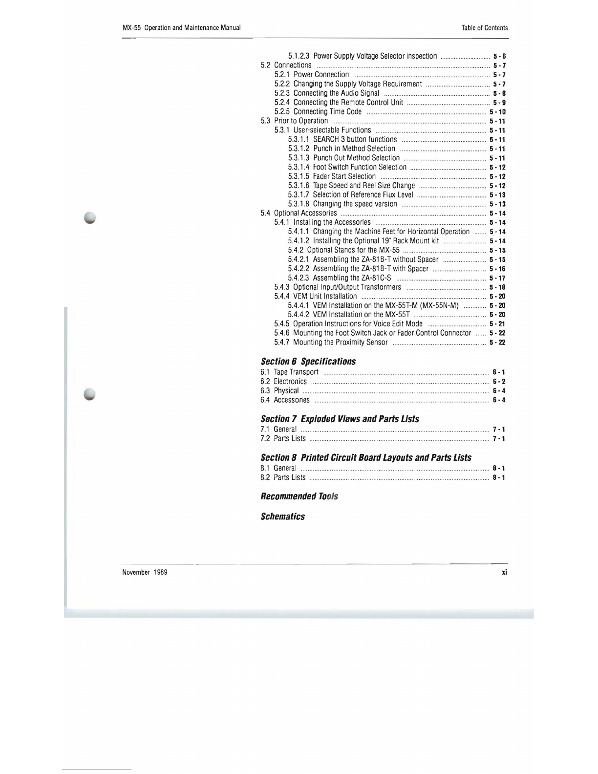
5.1.2.3
Power
Supply
Voltage
Selector
inspection
..........
....
....
...
..
.......
5·6
5.2
Connections
....
...................
...
...............
.
.......
..............................
.
........
..
..........
5·7
5.2.1
Power
Connection
............
....
..
..............
............
......
..
...........................
5·7
5.2.2
Changing
the
Supply
Voltage
Requirement
.....
.......
.
..
.
.... ..
...............
5·7
5.2.3
Connecting
the
Audio
Signal
....................................
..
......................
.
5·8
5.2.4
Connecting
the
Remote
Control
Unit
...............
...................
..
.
..........
.
5·9
5.2.5
Connecting
Time
Code
......
..............
....
........
.
......
..
.
..
.............
..
.
..
.......
5
·10
5.3
Prior
to
Operation
........................................................
..
.
..
...
........
..........
.......
5 ·11
5.3
.1
User-selectable
Functions
...............
..
.................
.....
..........
..
............
. 5 ·11
5.3.1.1
SEARCH
3
button
functions
....
.
..
.....................
......
...
..
..........
5
·11
5.3.1.2
Punch
In
Method
Selection
......
..
...............
................
.. ..
.......
5 ·11
5.3.1.3
Punch
Out
Method
Selection
.
......
........
...
......
....
....
................
5
·11
5.3.1.4
Foot
Switch
Function
Selection
.....
..
....
...........
......................
5
·12
5.3.1
.5
Fader
Start
Selection
....................
......
..
.....
.........
.
..................
5·12
5.3.1.6
Tape
Speed
and
Reel
Size
Change
..........
..
.. ..
.......................
5
·12
5.3
.
1.7
Selection
of
Reference
Flux
Level
..
....
......
.
..
....................
.....
5·13
5.3
.1.8
Changing
the
speed
version
............
...............
............
..
........
5
·13
5.4
Optional
Accessories
....................................
....
..
....
..............
......
....
........
......
5
·14
5.4
.1
Installing
the
Accessories
......
............
.......
..................
......
....
........
5
·14
5.4.1.1
Changing
the
Machine
Feet
for
Horizontal
Operation
.......
5
·14
5.4.1.2
Installing
the
Optional
19"
Rack
Mount
kit
............
.............
5
·14
5.4
.2
Optional
Stands
for
the
MX-55
..........
...............
..
.
....................
5
·15
5.4
.2.1
Assembling
the
ZA-81
B-T
without
Spacer
.........
....
..
..
........
5-15
5.4.2.2
Assem
bling
the
ZA-81
B-
T
with
Spacer
....................
..
....
.....
5
·16
5.4
.
2.3
Assem
bling
the
ZA-81
C-S
..........
.....
....
..
...................
..........
..
5·17
5.4.3
OptionallnpuVOutput
Transformers
....
...
...............
..
................
.
....
5
·18
5.4.4
VEM
Unit
Installation
..
.......
................
....
....
................
....
..
........
.
..
......
5·20
5.4.4.1
VEM
Installation
on
the
MX-55T-M
(MX-55N-M)
.......
......
5·20
5.4.4
.2
VEM
Installation
on
the
MX-55T
................
....
.. ..
..
.......
.........
5·20
5.4.5
Operation
Instructions
for
Voice
Edit
Mode
..................................
5·21
5.4.6
Mounting
the
Foot
Switch
Jack
or
Fader
Control
Connector
......
5·22
5.4.7
Mounting
the
Proximity
Sensor
........
..........................
................
....
5·22
Section
6
Specifications
6.1
Tape
Transport
.
..
..............
............
.....................
....
..
.................................
..
.....
6·1
6.2
Electronics
........
...............
.............
.........
.
.............
..
.................
..
..........
..
....
......
.
6·
2
6.3
Physical
..........
............
.......................
........
..
..................
..
...........................
...
.
6·
4
6.4
Accessories
..........
....
.....
....
........
....
.......
......
......
........
.............
..
........................
6·
4
Section
7
Exploded
Views
and
Parts
Lists
7.1
General
..
..
..........
..............
......................................
.
........................
..
................
7·1
7.2
Parts
Lists
...............................................
..
..
....
....
......
........................
..
.. ..
..
...
...
7·1
Section
8
Printed
Circuit
Board
Layouts
and
Parts
Lists
8.1
General
......
...
............................
.....
.......................
........
......
..
.................
.........
8·1
8.2
Parts
Lists
............
......
..
........
...
......
....
..
.....................
....
........
.....
...
...........
8-1
Recommended
To
ols
Schematics
November
1989
xi

xii
Table
of
Contents
MX-55
Operation
and
Maintenance
Manual
List
of
Figures
Figure
2-1
Tape
Transport
.
....
...
..
..
...............
.
......
.
......
.
.....
.
....
.
....
...
..
..
.....
....
.....
2
·1
2-2
Transport
Control
Panel
..
....
...
.........
.....
.
..
..
................
..
...
..............
2·4
2-3
Head
Assembly
.......
..
.......
...............
....
.......
..
..
..........
..
....
.
...........
.2
·12
2-4
Amplifier
Panel
......
..
...........................
.............
.
..
.....
.....
..
....
..
.....
.2
-13
2-5
Amplifier
Connector
Panel
..
..
......
.....
.......
.................
..
....
........
....
2
·19
2-6
Transport
Connector
Panel
....
..........
...........................
.......
..
..
....
2·21
2-7
Controls
on
the
Audio
Amplifier
PCB
Assembly
........
..
..
..........
.2-
23
2-8
Controls
on
the
Mic
Amplifier
PCB
Assembly
...................
......
2·24
2-9
Controls
on
the
Mother
Board
PCB
Assembly
..
.
.... ....
....
..
..
..
..
.
2·25
Figure
3-1
Reel
Spindle
...
..
................
...
.....
..
....
..
.
........
...
...........
....
..
...........
.....
3·1
3-2
Mounting
the
Reel
Table
....
..
.
..
.................
..
...
..
......
....
....
...............
3·1
3-3
Mounting
the
AEG
(DIN)
Hub
Adapter
..........
....
....
........
...
..
........
3-1
3-4
Tape
Threading
........
.
..
....
..
......
.
....
.........
.....
....
......
..........
..
.. ..
.
........
3·2
3-5
Editing
the
TApe
..
.......
..
..........
............
.....
....
..........
..
...
.
..
.....
.........
3
·15
Figure
4·1
Demagnetizing
the
Heads
....
...
........
................
...
..
.
......
......
.
..
........
4·2
4-2
Cleaning
the
Heads
..
..
....
..
.
............
....
.. ..
..........................
.......
....
...
4·3
4-3
Capstan
M
oto
r
Bearing
Lub
rication
....
...........................
....
......
..
4·4
4-5
H
ead
He
ight
and
Zenith
Adjustment
.... ....
...
....
......
..
..
...
..
...
......
..
..
4 - 7
4-6
Wear
Patterns
......
...........
......
.....
..
....................
....
..........
..
....
..
......
4·7
4-7
Measuring
Reel
Table
Height
.....
..
....
..
....
..
........
..
............
......
.......
4·8
4-8
Reel
Table
Adjustment
.....
...
.
......
..
.........
.
........
.........
.....
.. .. ..
..........
4·9
4-9
Reel
Brake
Tension
Measurements
...........
..........
..
..
.............
.
..
.4
-10
4-10
Reel
Brake
Adjustment
......
..
..............
.....
..
...
..................
.......
..
.
...
4 -11
4-11
Pinch
Roller
Pressure
Measurement
....
...
..
..
..
....
..
.......
..
..
......
....
4
-12
4-12
Pinch
Roller
Pr
es
sure
Adjustment
.......
..
..
.
......
..
..
....
..
..
......
....
...
4·13
4-13
Tape
Lifter
Clearance
Measurement
........
........................
.......
..
4
·14
4-14
Tape
Lifter
Adjustment
....
....
...........
...........
.
..
..
......
.....
....
......
.....
..4
·14
4-15
Controls
on
the
Transpo
rt
Control
PCB
Assembly
..
....
............
4
·15
4-16
Capstan
Waveform
Display
...
..
.......
.......
........................
...........
.4
-15
4-17
Capstan
Servo
Block
Diagram
.......
.....
...
..
..
............
..
..
......
....
..
...
4
-16
4-18
Audio
Amplifier
Block
Diagram
......
..
.
...
........
..
.....................
......
4
·18
4-19
Location
of
Trimmers
on
Audio
Amplifier
PCB
Assembly
....
.4
-19
4-20
Test
Oscillator
Waveform
....
.
..........
.....
........
....
..
..........
.............
..
4 -
20
4-21
Azim
uth
Test
Set-Up
......
..
............
.
..
..
......
...............
....
....
..
..
......
..
4 -
23
4-22
Azimuth
Adjustment
Screws
......
..
..
..............
..
....
....
..
..
...............
4 -
23
4-23
Azimuth
Adjustment
Displays
..
....
..
..........................
...
..........
....
4 -
23
4-24
Location
of
Trimmers
on
Audio
Amplifier
PCB
Assembly
...
4·24
4-25
Adjustment
Points
and
Amplitude
Adjustment
............
..
.... ....
.
..
4·27
4-26
Re
cord
Azimuth
Adjustment
Set-Up
...
..
.........
...
.......
..
.....
..
.
..
....
4 -
29
4-27
Re
c
ord
Head
Azimuth
Oscilloscope
Display
.....
..
...
..
....
......
......
4 -
30
Figure
5-1
Opening
the
Amp
Top
Panel
..
...
.
........
........
..
...........
......
.......
........
5 - 3
5-2
Opening
the
Transport
Rear
Panel
..
............
..
..
..
..
..
...
.
............
......
5·4
5-3
Pin
Assignment
of
Power
Connector
.........
....
..
........
..
............
....
5·7
5-4
Voltage
Select
Wiring
........
.............
....
....
.
.........
....
....
....
....
..
......
....
5 - 7
5-5
Audio
Connector
Wiring
..
..
.....
....
..
..
........
..
...
......
...
......................
.5 - 8
5·6
Connection
of
the
Machines
....
..
........
..
...................
....
.
..
..
..
........
5
-10
5-7
Installing
Rear
Legs
............
......
.
........
.
..
.
..
..........
.........
..
.............
5
-14
5-8
Mounting
the
ZA-SCG
Rack
Adapter
..............
..
....
.
....
....
..
....
.....
5
-14
5-9
Mounting
Hole
Spacing
.. ..
........
......
........
....
....
...
....
.........
....
....
...
5
-14
5-10
Assembling
the
ZA-81
B-
T
Pedestal
.......
..
.
..
...
.
........
.
..
..
....
......
...
5
·15
5-11
Assembling
the
ZA-81
B-
T
Pedestal
with
Spacer
..
...
..........
.....
5
·16
4-4
Head
Posi
tion
Ad
jus
tment
Screws
......
....
..
...............
.........
.. ..
.....
4-7
November
1989
MX-55
Operation
and
Maintenance
Manual
Table
of
Contents
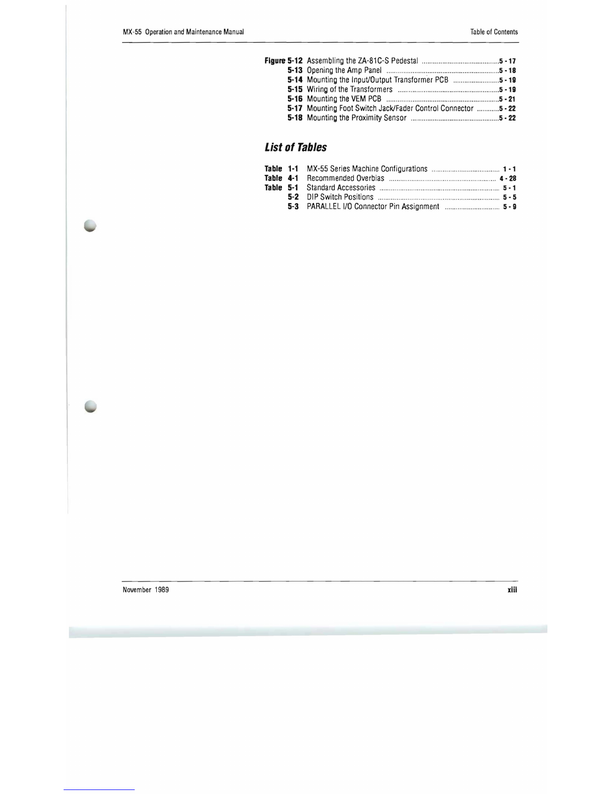
Figure
5-12
Assembling
the
ZA-81C-S
Pedestal
....
..
.
..
....
..........
.
..
..
.
..
..
.....
....
5-17
5-13
Opening
the
Amp
Panel
........
..
......
..............
....
......
......
......
..
....
...
5
-18
5-14
Mounting
the
Input/Output
Transformer
PCB
......
......
..
....
......
.5
-19
5-15
Wiring
of
the
Transformers
........
....
........
..
......
....
....
....
..
......
..
.....
5
-19
5-16
Mounting
the
VEM
PCB
....
....
.. ....
......
......
........
..
....
......
....
......
..
..
.5 -
21
5-17
Mounting
Foot
Switch
Jack/Fader
Control
Connector
..
....
......
5 -
22
5-18
Mounting
the
Proximity
Sensor
..
........
....
........
..
........
..
....
......
....
5 -
22
List
of
Tables
Table
1-1
MX-55
Series
Machine
Configurations
...........
....
......
..
....
.........
. 1 -1
Table
4-1
Recommended
Overbias
..
....
..
.
....
....
..
....
....
......
...........
....
......
..
..
4 -
28
Table
5-1
Standard
Accessories
....
..
......
..
....
....
................
....
......
........
........
.
5-1
5-2
DIP
Switch
Positions
................
.
..
......
.........
....
............
....
....
....
..
..
5 - 5
5-3
PARALLEL
I/O
Connector
Pin
ASSignment
..
........
..
....
.
........
.....
5 - 9
November
1989
xiii

MX-55
Operation
and
Maintenance
Manual
Introduction
Section
1
Introduction
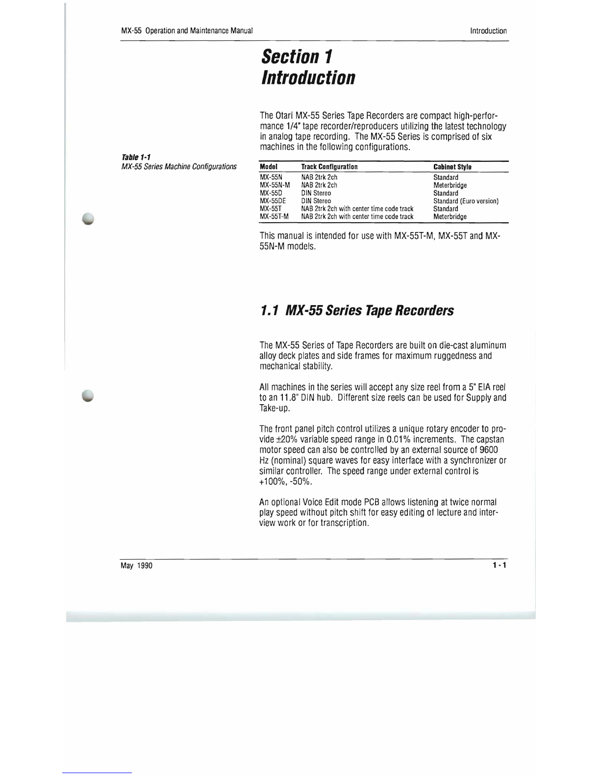
The
Otari
MX-55
Series
Tape
Recorders
are
compact
high-perfor-
mance
1/4"
tape
recorder/reproducers
utilizing
the
latest
technology
in
analog
tape
recording
.
The
MX-55
Series
is
comprised
of
six
machines
in
the
following
configurations.
Table
1-1
MX-55
Series
Machine
Configurations
Model
Track
Configuration
Cabinet
Style
MX-55N
NAB
2trk
2ch
Standard
MX-55N-M
NAB
2trk
2ch
Meterbridge
MX-55D
DIN
Stereo
Standard
MX-55DE
DIN
Stereo
Standard
(Euro
version)
MX-55T
NAB
2trk
2ch
with
center
time
code
track
Standard
MX-55T-M
NAB
2trk
2ch
with
center
time
code
track
Meterbridge
This
manual
is
intended
for
use
with
MX-55T-M,
MX-55T
and
MX-
55N-M
models.
1.1
MX-55
Series
Tape
Recorders
The
MX-55
Series
of
Tape
Recorders
are
built
on
die-cast
aluminum
alloy
deck
plates
and
side
frames
for
maximum
ruggedness
and
mechanical
stability.
All
machines
in
the
series
will
accept
any
size
reel
from
a
5"
EIA
reel
to
an
11.8"
DIN
hub.
Different
size
reels
can
be
used
for
Supply
and
Take-up.
The
front
panel
pitch
control
utilizes
a
unique
rotary
encoder
to
pro-
vide
±20%
variable
speed
range
in
0.01
%
increments.
The
capstan
motor
speed
can
also
be
controlled
by
an
external
source
of
9600
Hz
(nominal)
square
waves
for
easy
interface
with
a
synchronizer
or
similar
controller.
The
speed
range
under
external
control
is
+
100%,
-50%.
An
optional
Voice
Edit
mode
PCB
allows
listening
at
twice
normal
play
speed
without
pitch
shift
for
easy
editing
of
lecture
and
inter-
view
work
or
for
transcription.
May
1990
1-1

Introduction
MX-55
Operation
and
Maintenance
Manual
The
built-in
tape
timer
displays
the
current
tape
position
as
Hours
,
Minutes
and
Seconds,
or
the
tape
speed
in
inches
per
second,
or
the
tape
speed
as
a
percentage
of
change
from
the
selected
play
speed.
The
tape
timer
incorporates
a
four
point
search-to-cue
locator
with
three
cue
point
memor
ies
and
a
zero
location
memory.
The
includ-
ed
repeat
function
allows
continuous
repeat
play
between
any
two
selected
cue
pOints.
One
cue
point
memory
can
be
set
to
store
the
location
where
Play
or
Record
was
last
entered,
for
easy
return
to
the
beginning
of
a
sequence
or
take.
All
machines
in
the
Series
feature
front
panel
selection
of
two
oper-
ating
speeds,
with
internal
switch
selection
of
either
High
(15
ips
and
7.5
ips)
or
Low
(7.5
ips
and
3.75
ips)
speed
pair
operat
,
ion.
The
MX-55
Series
ma
chines
provide
switc
h
selection
of
NAB
or
lEG
equalization;
+4
dBm
or
-16
dBm
Input
and
Output
levels;
185,
250
or
370
n
Wb
/m
Reference
Fl
ux
level
with
front
panel
indication
of
Reference
Flux
lev
el
and
eq
ualization.
XL
type
connectors
are
pro-
vided
for
Inputs
and
Outpu
ts
with
transformerless
active
balanced
Circuit
ry.
The
MX-55
Ser
ies
mach
ine
s
also
provide
the
HX
Pro·
Headroom
Extension
System.
HX
Pro
improves
the
high
frequency
perfor-
mance
of
any
tape
recorded
on
the
MX-55
by
analyzing
the
high
fre-
quency
components
of
th
e
au
dio
signal
and
continuously
adjusting
recording
bias
to
mai
nta
in
bias
linearity
for
optimum
distorUon,
noise,
and
frequency
response
characteristics.
HX
Pro
is
not
an
"encoding"
process,
and
does
not
require
any
decoding
during
playback.
*
Dolby
HX
Pro
:
HX
Pro
Headroom
Extension
originated
by
Bang
&
Olufsen
and
manufactured
under
license
from
Dolby
Licensing
Corporation.
UDolby"
and
the
Double-D
symbols
are
trademarks
of
Dolby
Li
censi
ng
Corporation.
1 - 2
November
1989

MX-55
Operation
and
Maintenance
Manual
Introduction
1.2
Using
This
Manual
This
manual
is
intended
for
use
with
MX-55T-M,
MX-55T
and
MX-
55N-M
model.
For
convenience,
the
descriptions
and
references
apply
to
MX-55T-M,
where
any
differences
exist
between
this
model
and
others
in
the
series,
those
differences
will
be
fully
explained
in
context.
1.2.1
Organization
This
manual
is
divided
into
nine
sections
beginning
with
this
INIRO-
DUCTION
which
contains
general
information
about
the
MX-55
Series
and
about
the
manual.
Section
2,
CONTROLS
AND
INDICATORS,
contains
a
keyed
reference
guide
to
the
operating
controls,
indicators
and
connectors
on
the
machine.
This
section
contains
detailed
information
about
each
control
and
its
function.
Refer
to
this
section
when
you
have
a
question
about
the
function
of
a
particular
control,
indicator,
or
con-
nector.
Section
3,
OPERATION
describes
the
operation
of
the
MX-55
machines,
and
is
divided
into
two
parts;
a.
A
table
of
machine
operating
modes,
which
lists
each
mode
and
the
controls
necessary
to
enter
that
mode;
and
b.
Detailed
operating
instructions,
which
describe
each
operation
and
the
controls
and
indicators
associated
with
that
operation.
Section
4,
MAINIENANCE
AND
ADJUSTMENT,
provides
the
infor-
mation
necessary
to
perform
routine
maintenance
operations,
including
head
cleaning
and
demagnetizing
and
capstan
motor
lubrication.
It
also
covers
the
audio
and
transport
adjustments
associated
with
normal
operation
of
the
machine.
Section
5,
INSTALLATION,
contains
the
information
necessary
when
first
unpacking
and
installing
the
machine.
The
information
and
procedures
contained
in
this
section
should
be
followed
very
care-
fully
when
the
machine
is
first
unpacked
and
installed.
Performing
the
inspection
and
checkout
steps
will
familiarize
you
with
the
machine
and
its
component
parts
if
this
is
your
first
contact
with
the
MX-55
series
of
tape
recorders.
November
1989
1 - 3
Introduction
MX-55
Operation
and
Maintenance
Manual
Section
6
lists
the
SPECIFICATIONS
of
the
MX-55T-M,
MX-55T
and
MX-55N
-M
tape
recorders.
Section
7,
EXPLODED
VIEWS
AND
PARTS
USTS,
contains
assembly
drawings
of
the
machine
"exploded"
to
show
internal
parts
and
hardware,
and
the
order
of
assembly.
Each
drawing
is
keyed
to
an
accompanying
Parts
List
containing
the
Otari
part
number
for
each
mechanica
'l
component.
Section
8,
PRINTED
CIRCUIT
BOARD
LAYOUTS
AND
PARTS
USTS,
contains
two-color
"X-ray"
views
of
the
printed
circuit
boards
(PCBs)
showirilg
component
locations
and
foil
traces.
This
section
also
contains
Parts
Lists
of
the
e'
lectronic
components
associated
with
each
PC'S.
The
final
section
contains
the
SCHEMATIC
DIAGRAMS
for
all
elec-
tronics
assemblies
and
pr
i
rlted
circuit
boards.
1.2.2
Conventions
within
this
manual
Generally
this
manual
uses
all
capital
letters
to
describe
a
control,
indicator,
or
connector
when
that
item
is
similarly
labeled
on
the
mach.ine
(e.g.,
INPUT
level
control
or
PARALLEL
lID
connector).
Where
a
control
or
indicator
is
not
labeled
on
the
machine,
the
name
of
that
item
,
is
spelled
with
initial
cap
'
italletters
only
(e.g.,
Mic
Input
connector
or
Cue
Spea
'
ker).
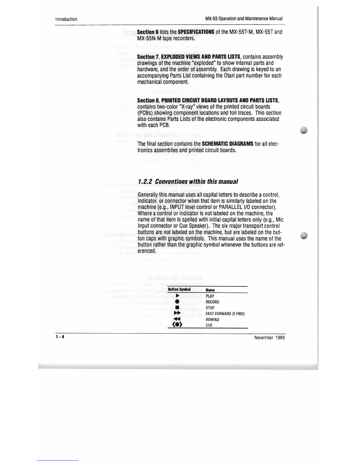
The
six
major
transport
control
buttons
are
not
labeled
on
the
machine,
but
are
labeled
on
the
but-
ton
caps
with
graphic
symbols.
Th
l
is
manual
uses
the
name
of
the
button
rather
than
the
graphic
symbol
whenever
the
buttons
are
ref-
erenced.
BuHonSynoi
Name
PLAY
RECORD
STOP
FAST
FORWARD
(F.
FWD)
REWIND
CUE
1
·4
November
1989
This manual suits for next models
2
Table of contents
Other OTARI Recording Equipment manuals

OTARI
OTARI MX-5050 User manual

OTARI
OTARI MX-5050 BII Series User manual

OTARI
OTARI MX 5050 BQII Series User manual

OTARI
OTARI MX-505MKIV-2 Manual

OTARI
OTARI MTR-90III User manual

OTARI
OTARI RADAR User manual

OTARI
OTARI MX-50II Series User manual

OTARI
OTARI MX-505MKIII-2 User manual

OTARI
OTARI MX-5050 Manual

OTARI
OTARI MX-5050BII Series User manual


