OTARI MX-505MKIV-2 Manual
Operation
&
Maintenance
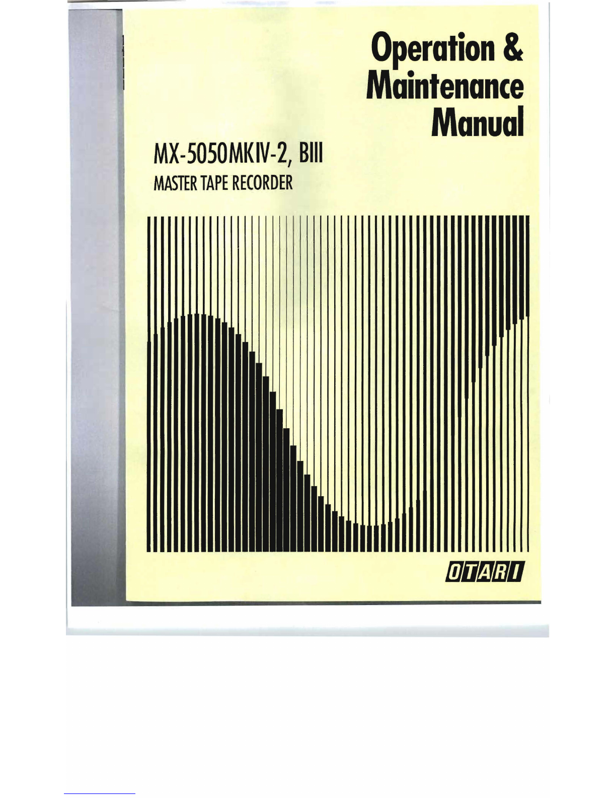
MX-5050MKIV-2,
Bill
Manual
MASTER
TAPE
RECORDER
I ,
, I
11'
.-.-.-.-.
lflfi!iJCJD

Part
No.
OS3-298
1!10!iJliJU
MX·5050
MKIV-2,
8111·2
MASTER
TAPE
RECORDER
OPERATION
AND
MAINTENANCE
MANUAL
THIRD
EDITION
Printed
:
May
1992
Otari,
Inc.
Ed
3
(WM)

Copyright
©
1992
Otari,
Inc
.
and
Otari
Corporation
Printed
in
Japan
This
manual
may
not
be
reproduced
by
any
means
without
written
permission.
s

CAUTION
To
prevent
fire
or
shock
hazard:
Do
not
expose
this
un
it
to
rain
or
moisture.
Do
not
remove
panels
(unless
instructed
to
do
so).
There
are
no
user-serviceable
parts
inside
.
Refer
servicing
to
qualified
service
personnel.
PLEASE
READ
THROUGH
THE
SAFETY
INSTRUCTIONS
ON
THE
NEXT
PAGE.
1.
Read
Instructions
2.
Retain
Instructions
3.
Heed
Warnings
4.
Follow
Instructions
5.
Water
and
Moisture
6.
Carts
and
Stands
7.
Ventilation
8.
Heat
9.
Power
Sources
10.
Grounding
or
Polarization
11.
Power
Cord
Protection
12.
Cleaning
13.
Non-Use
Periods
14
Object
and
liquid
Entry
15.
Damage
Requiring
Service
16.
Servicing
iv
SAFETY
INSTRUCTIONS
All
the
safety
and
operating
instructions
should
be
read
before
the
device
is
operated.
The
safety
and
operating
instructions
should
be
retained
for
future
.
All
warnings
on
the
device
and
in
the
operating
instructions
should
be
adhered
to.
All
operating
and
use
instructions
should
be
followed
.
The
device
should
not
be
used
near
water
-
for
example,
near
bathtub,
wash
bowl,
kitchen
sink,
laundry
tub,
in
a
wet
basement,
or
near
a
swimming
pool,
etc.
The
device
should
be
used
only
with
a
cart
or
stand
that
is
recommended
by
the
manufacturer.
The
device
should
be
situated
so
that
its
location
or
pOSition
does
not
interfere
with
its
proper
ventilation.
For
example,
the
device
should
not
be
situated
on
a
bed,
sofa,
rug,
or
similar
suriace
that
may
block
the
ventilation
openings;
or,
placed
in
a
built-in
installa-tion,
such
as
a
bookcase
or
cabinet
that
may
impede
the
flow
of
air
tl
l
rough
the
ventilation
openings
.
The
device
should
be
situated
away
from
heat
sources
such
as
radiator,
heat
registers
,
stoves
or
other
appliances
(including
amplifiers)
that
produce
heat.
The
device
should
be
connected
to
a
power
supply
only
of
the
type
described
in
tile
operating
instructions
or
as
marked
on
the
device
.
Precaut
i
ons
should
be
taken
so
that
the
grounding
or
polariza-tion
means
of
the
device
is
not
defeated
.
Power
supply
cords
should
be
routed
as
they
are
not
likely
to
be
walked
on
or
pi
nched
by
items
placed
upon
or
against
them,
paying
particular
attention
to
cords
at
plugs
,
convenience
recep-tacles,
and
the
point
where
they
exit
from
the
device.
The
de
v
ice
should
be
cleaned
only
as
recommended
by
the
manufacturer.
The
power
cord
of
the
device
should
be
unplugged
from
the
out-let
when
lett
unused
for
a
long
period
of
time.
Care
should
be
taken
so
that
objects
do
not
fall
and
that
liquids
are
not
sp
i
lled
into
the
enclosure
through
openings.
The
device
should
be
serviced
by
qualified
service
personnel
when:
A.
The
power-supply
cord
or
the
plug
has
be
en
damaged;
or
B.
Objects
ha
ve
falle
n,
or
liqu
id
has
been
spilled
into
the
appliance;
or
C.
The
appliance
has
been
exposed
to
rain;
or
D.
The
appliance
does
not
appear
to
operate
normally
or
ex
hibits
marked
change
in
performance;
or
E.
The
appliance
has
been
dropped
,
or
the
enclosure
damaged
.
The
user
should
not
attempt
to
service
the
device
beyond
that
described
in
the
operating
instructions
.
All
other
service
should
be
referred
to
qualified
personnel.
re
the
device
is
future
,
;
hould
be
Ir
bathtub,
wash
;wimming
pool,
ommended
by
1S
not
interfere
e
situated
on
a
'
penings;
or,
'
at
may
impede
radia
lor,
heat
produce
heat.
Ipe
described
on
means
of
walked
on
lar
aNention
they
exit
facturer,
et
when
left
e
not
e;
or
marked
r
ibed
in
~alified
COMMUNICATION
WITH
OTARI
FOR
SERVICE
INFORMATION
AND
PARTS
All
Otari
products
are
manufactured
under
strict
quality
control.
Each
unit
is
carefully
inspected
and
tested
prior
to
shipment.
If,
however,
some
adjustment
or
technical
support
becomes
necessary,
replacement
parts
are
required,
or
technical
questions
arise,
please
contact
your
Otari
dealer
or
contact
Otari
at
Ot
arl,
Inc.
Otari
Corporation
4-33-3
Kokuryo-cho
378
Vintage
Park
Drive
Chofu-shi,
Toky0182
Foster
City
Japan
California
94404
USA,
Phone
:
(0424)
81-8626
Phone
:
(415)
341-5900
Telex
:
J26604
OTRDENKI
Telex
:6503028432
MCI
UW
Fax:
(0424)
81-8633
Fax:
(415)
341-7200
Cable
:
OTAR
I
DENKI
TOKYO
Otarl
Deutschland
GmbH_
Olari
Singapore
Pte.,
Ltd
Rudolf-Diesel-S
tr
12
625
Aljunied
Road
0-4005
Meerbusch
2
(Oslerath)
#07
-
05
Aljunied
Industrial
Complex
FRGermany
Singapore
1438
Phone
:
(02159)
50861
Phone
:
(743)
7711
Telex
:
8531638
OTEL
0
Telex
,
RS
36935
OTARI
Fax
:
(02159)
1778
Fax:
(743)
6430
O
tari
(U
.
K.)
Limited
Unit
13,
Elder
Way,
Waterside
Drive,
Langley,
Slough,
Berkshire
SL3
6EP
United
Kingdom
Phone
:
(0753)580777
Telex
:
849453
OTARI
G
Fax:
(0753)
542600
Another
part
of
Otari
's
continuing
technical
support
program
for
our
products
is
the
continuous
revision
of
manuals
as
the
equipment
is
improved
or
modified
,
In
order
for
you
to
receive
the
information
and
support
which
is
applicable
to
your
eqUipment,
and
for
the
technical
support
program
to
function
properly
,
please
include
the
following
information,
most
of
which
can
be
obtained
from
the
Serial
number
label
on
the
machine,
in
all
correspondence
with
Otari:
•
Model
Number:
•
Serial
Num
ber
:
•
Date
of
Purchase:
•
Name
and
address
of
the
dealer
where
the
ma
c
hine
was
purchased
and
the
power
requirements
(voltage
and
frequency)
of
the
machine,
v

Table
01
Contents
Safety
Instructions
.
..
.......
....
.....
......
..
........
.......
......
.. v
..
...
....
....
..
........
....
vii
Communication
with
Otari
Section
1
Introduction
1.
1
MX-5050
Series
... ..
.....
.....
...
....
...
...
1-2
1.2
Using
This
Manual
....
..........
...
....
..
1-3
1.2
.1
OrgJnization
......
.
......
.
.......
.
..
...
......
1-3
1.2.2
Conventions
within
this
manual
.. .. .
...
.
..................
....
....
1-4
Section
2
Instal/aion
2.
1
Unpa
c
king
and
Inspection
. .... ........
...
........
.. .
2-2
2.2
Audio
Signal
Conne
c
tion
..
. ....
...
.. ..
....
.
.......
2-3
2.2.1
Audio
Conn
ec
tors
.
.......
.....
.....
.. .
..
.....
..
..........
...
...
.
2-3
2.2
.2
BJlJnce
/
Unbalance
Adju
s
tment
. .
..
...
....
.......
.. ... ....
....
.
2-4
2.3
Switch
Position
Adjustment
. . .. ..
......
..
...
2-5
2.4
PCB
Assembly
Location
. ..
.....
..
...
.. ..
........
...
2·9
2.
4 1
MX-5050
Bill .
....
...
2-9
24.2M
X-
5050
MKIV2
.
2·11
2.5
Po
w
er
Connection
.
2-13
2.6
Fuse
Replacement
.......... .
...
... .
....
..
.....
...... .. .. ..
....
2-
14
2.7
Speed
Conversion
(BIJI-2)
. .
.....
.
....
.....
.......
2-15
2.8
Equalizer
Change
........... . .
2-15
Section
3
Controls
and
Indicators
3.
1
Tape
Transport
.
....
.. .
3-2
3.2
Transport
Control
Panel
.. .. ..
...
.. ...
3-3
3.3
Head
Assembly
......
....
. ....
3-6
3.4
Amplifier
Panel
...
..
3-7
3.5
Audio
Connector
Panel
.
3-9
3.6
Conne
c
tor
Pin
Assignment
s
......
..
.....
3-12
Section
4
Operation
4.1
Operation
Mode
Reference
Tables
....
..
....... .
..
........
..
..
4-2
4.2
Modes
of
Operation
..
...
..
..
..
.
..
4-3
4.2.1
TrJl1spol1
Mo
de
s . .. ..
.....
. .
....
......
... ...... .. .. ..
4-3
4.2.2
Alidio
Channel
Mo
de
s
4-4
......
...
.. . ....
....
.. . ...
....
..
....
.......
Ma
y
1992
vii
Table
of
Contents
MX-SOSO
Operation
and
Maintenance
Manual
4.3
Operating
the
MX-5050
.. . ...
...
...
....
4-5
4.3.1
Placing
Reels
on
the
Machine
.....
.
.......
.. .. .. .
............
4-5
4.3.2
Threading
th
e
Tape
.. .. .
........
4·6
4.4
Operation
of
the
Transport
... ... .
........
4-7
4.4.1
Playing
Back
the
Tracks
....
4-7
4.4.2
Recording
the
Tracks
... ....
...
.. .... .
.......
4·
7
4.4.3
SEL-REP
Recording
...
.....
.. .. . ..
...
..
...
.............
4·8
4.4.4
Fast
Wind
and
CUE
Monit
or ...
...
.
....
... .
.....
.
....
.... .....
....
4-8
4.4
.5
Tape
Editing
....
.
.........
4-9
4.4
.6
Using
the
Pitch
Contr
ol
Fe
a
ture
..
..
....
..
....
....
...
..
4-10
4.5
Locator
Operation
.
......
.. ... ...
...
.....
...
..
....
.
.......
..
......
4-
11
4.5.1
Storing
Tape
Locations
4-11
4.5.2
Sear
ch
Mode
.. ..
....
.... .. . .. .....
..........
4-11
4.5.3
Search
Play
Mode
.. 4-
12
4.54
Search
Zero
Mode
..............
4-12
4.5.5
Search
Start
Mode
.. 4-
12
4.5.6
Repeat
Mode
. .. .
.........
..
..
....
........
4-13
4.6
Test
Oscillator
. .
.............
4-
13
Section
5
Maintenance
5.1
Maintenance
Scheduling
...
5·2
5.2
Demagnetizing
...
5·2
5.3
Cleaning
the
Tape
Path
. .
...
.
...........
.
..
.
.....
......
5-3
5.4
Lubrication
.... ...... ..
....
.... ...
.....
5·4
Section
6
Transport
Adjustment
and
Parts
Replacement
6.1
Transport
Access
.....
6-2
6.2
Brake
Torque
Adjustment
. ..
....
6-2
6.3
Tape
Lifter
Adjustment
....
6-4
6.4
Capstan
Motor
Adjustment
and
Pitch
Control
Adjustment
... 6·5
6.5
Pi
nch
Roller
Pressure
Adjustment
.
6·6
6.6
Tape
Speed
Adjustment
..
6-8
6.7
Reel
Table
Height
Adjustment
. 6·9
6.B
Head
Assembly
Replacement
'...
..
.
..
... ... .
..
..
.............
6-10
6.9
Head
Pos
i
tion
Adjustment
.....
6-11
J
viii
May
1992
hC
j
Maintenance
Manual
..
...
...
.......
4-5
'"
4-5
....
..
...
4-6
...
...
4-7
....
4-7
.. ..
4-7
.....
4-8
.....
..
...
4-8
.. .
4-9
..
4-10
....
4-11
. .
.....
4-11
...
. ...
4-11
...
.
4-12
. ..
..
..
4-12
.....
4-12
....
4-13
...
......
4-
13
....
5-2
5-2
....
5-3
'"
5-4
~menl
'" 6
-2
..
6-2
......
6-4
7ent
...
6-5
.
6-6
' ..
6-8
.. ..
6-9
6-10
6-11
MX-5050
Operat
i
on
and
Maintenance
Manual
Table
of
Contents
Section
7
Audio
Alignment
7.
1
Tools
and
Equipment
Required
.....
....
7-2
7.2
Block
Diagrams
.......
..
7-3
7.2
.1
Peak
Indicator
Level
Adjustment
..
7-3
7.2
.2
Test
Oscillator
Waveform
and
Level
Adjustment
.. . .. .. .
.....
.....
7-4
7.3
Reproduce
Adjustments
. .
7-5
7.3.1
Reproduce
Head
Azimuth
Adjustment
...
....
..
.... ...
........
....
7-5
7.3
.2
Reproduce
Level
Adjustment
.....
..
......
...
..........
......
7-6
7.3.3
Reproduce
Equalization
Adjustment
...
...
...
.
.......
.
7-7
7.4
Record
Electronics
Adjustments
........
... ...
....
...
..........
7-8
7.
4.1
Record
Bias
Level
Adjustment
....
.
.......
7-8
7.4
.2
Record
Head
Azimuth
Adjustment
.. .. .... ... ....... ..
7-9
7.4.3
Record
'level
Adjustment
.... .
...
.. .. .
7-10
74.4
Record
Equalization
Adjustment
.. .
.....
7-11
7.4.5
Low
Frequency
Reproduce
Equalization
Adlustment
.
7-11
7.
46
SEL-REP
Level
Ad
j
ustment
.. .
.....
.......
7-12
Section
8
Specifications
8.1
Tape
Transport
..
8-2
8.2
Electoronics
...
.. 8-3
Section
9
Exploded
Views
and
Bill
..'
.
9-2
-
9-19
MKIV-2
. ...
9-20
-
9-39
Appendix
Block
Diagram
Troubleshooting
Hints
(Electronics)
Troubleshooting
Hints
(Transport)
Index
Schematic
Diagrams
May
1992
Ix
May
1992
List
of
Figur
es
Figure
1-1
Exterior
Appearance
....
..
.
.....
...
..
......
... .
.....
1-2
Figure
2-1
Audio
Connectors
......
.....
.
.........
....
.....
.
.....
2-3
2-2
Balanced
/
Unbalanced
Connectors
..
..
.................
2-4
2-3
Switch
Setting
on
Rear
Panel
...
....
.........
..
........
2-5
2-4
Controls
on
the
CONTROL
PCB
Assembly
.
......
....
..
2-6
2-5
PCB
Assembly
Location
(Bill)
.....
...
......
.
....
....
..
2-9
2-6
AIVIP
Section
Rotation
(Bill) .
....
... ..
.....
....
.......
2-9
2-7
CONTROL
PCB
Assembly
Rotation
(Bill) ..
......
... ..
2-10
2-8
PCB
Assembly
Location
(MKIV-2)
..
...
.. .. .. .. ..
....
.
2-11
2-9
CONTROL
PCB
Assembly
Rotation
(MKIV-2)
.. ..
.....
2-12
2-10
Power
Connect
i
on
...
.......
.....
.....
.....
.....
.. ...
2-13
2-11
AC
Line
Voltage
Connector
....
.....
...
...
..........
...
2-13
2-12
Fuse
Location
.. .. ..
....
....
......
....
.....
......
.....
.
2-14
Figure
3-1
Tape
Transport
... ...
....
.. .... ........
.......
......
3-2
3-2
Transport
Control
Panel
..
..... .. ....
.......
..
...
.....
.
3-3
3-3
Head
Assembly
....
.. .
....
..
.....
......
... .. 3-6
3-4
Amplifier
Panel
(MKIV
-
2)
...
....
.... ..
.....
....
....
...
3-1
3-5
Audio
Connector
Panel
(Bill) .
..
....
... .
........
3-1
3-6
Audio
Connector
Panel
(MKIV-2)
... ..
......
.
.......
3-10
Figure
4-1
Tape
Threading
...... ... .
........
.....
....
.
...
.
.....
4-6
4-2
Edit
i
ng
a
Tape
. .. ... ..
.....
.......
4-10
Figure
5-1
Demagnetiz
i
ng
the
Head
...
.. .
......
...
.....
5-2
5-2
Cleaning
the
Head
.'
..
...
.....
...
5-3
5-3
Lubrication
... ..
...
.....
.....
.. .
5-4
Figure
6-1
Brake
Torque
Measurement
.
....
..
....
... .......
.....
6-2
6-2
Brake
Torque
Adjustment
.
.......
...
.....
...
..
......
..
6-3
6-3
Tape
Lifter
Adjustment
...
...
.....
.....
...
.. .. ..... 6-4
6-4
Waveform
on
Oscilloscope
...
.....
.....
..
....
....
....
6-5
6-5
Pinch
Roller
Pre
s
sure
Measurement
.....
........
... ..
6-6
6-6
Pinch
Roller
Solenoid
.
....
.....
.... ..
......
...
...
6-6
6-7
Pinch
Roller
Pressure
Measurement
......
.. ... ....
...
6-1
6-8
Re
el
Table
Height
Adjustment
....
..
.......
....
........
6-9
6-9
Head
Assem
bly
Repl
acem
ent
.. .. ........ .........
6-10
6-10
Height/Zenith
Adjustment
.. ....
...
..
....
...
...
6-11
6-11
Wrap
Adjustment.
... . ....
...
... ....
6-12
Figure
7-1
REC/REP
AMP
PCB
Assembly
..
..
.. ...
....
.
..
.... ..
....
1-4
7-2
Head
Adjustment
Screws
.. ... .. .........
.....
.
1-5
7-3
Wave
Shape
on
the
Oscilloscope
.
....
....
......
....
..
1-6
7-4
Head
Assemb
ly
......
....
...
.. ..... .
.....
..... ..
1-9
7-5
Waveshape
on
the
Oscilloscope
...
.....
....
....
..
......
.
1-9
May
1992
xl

List
of
Tables
Table
2-1
Standard
Accessories
...
.........
............
...
...
...
2-2
2-2
Settings
on
Rear
Panel
................................
2-5
2-3
DIP
SW
Setting
on
the
Control
PCB
..
.....
...
.....
.
......
2-6
2-4
Capstan
PLL
Refe
rence
...
.
....
...
....
....
.
..............
2-7
2-5
SEARCH
3
Key
Function
.....
...
,
...
.
........
..
...
.
......
2-7
2-6
Machine
Type
.
.......
"
.....
..
....
.
.....
,
....
...'"
.....
2-8
2-7
Fuse
Specificat
i
ons
....
...
... ......
...
.................
2-15
Tab
'
le
3-1
Parallel
110
Pin
Assign
ments
...
.
..................
..
3-12
3-2
Connector
Pin
21,
22
... .. .... .. .
........
.....
" 3-
12
3-3
Remote
Control
Connector
(MKIV-8
Option)
.. ..
......
3-13
Table
4-1
Transport
Modes
...........
...
......
.
...
.............
4-2
4-2
Audio
Channel
Modes
......
.....
........
...
........
...
4-2
4-3
Auto
Locator
Modes
.
................
.
.................
4-2
4-4
Vari
Pitch
Preset
..
.. .
...
...
...
.......
.....
.
.....
4-10
4-5
Cue
Point
Set
Mode
... ... .
......
..
.....
.........
..
...
4-11
Table
5-1
Maintena
nce
Time
Table
........
.
............
... .
.....
5-2
5-2
Too
ls
Required
for
Ma
intenance
...
...
...
.... ...
...
.
.....
5-2
Table
6-1
Necessary
Tools
..... .. ..
....
...
...
.
6-2
6-2
Brake
Tension
Values
..
.
..
.
....
.......
...
6-3
6-3
Tape
Speed
Settings
.
..
.
....................
6-8
Table
7-1
Reference
Tapes
.
...
... .
.....
........
.....
....
.. .
....
7-2
7-2
Trigger
Level
.....
....
........
7-3
7·3
Overbias
Values
....
.
.........
....
...............
..
.....
7-8
May
1992
xiii
Section
1
Introduction
This
Section
includes
a
general
description
of
the
features
of
the
MX-5050
series
tape
recorders
and
information
on
the
structure
of
this
manual.
1.1
MX-5050
Series
... 1-2
1.2
Using
This
Manual
. ...
....
.
......
1-3
1.2.1
OrgJnizJtion
1.2.2
Convent
i
ons
within
th
is
mJnuJI
...
... . .
....
1-3
....
.. .. ..... .
1-4
May
1992
1 - 1
Section
1
Introduction
MX
-5050
Operation
and
Maintenance
Manual
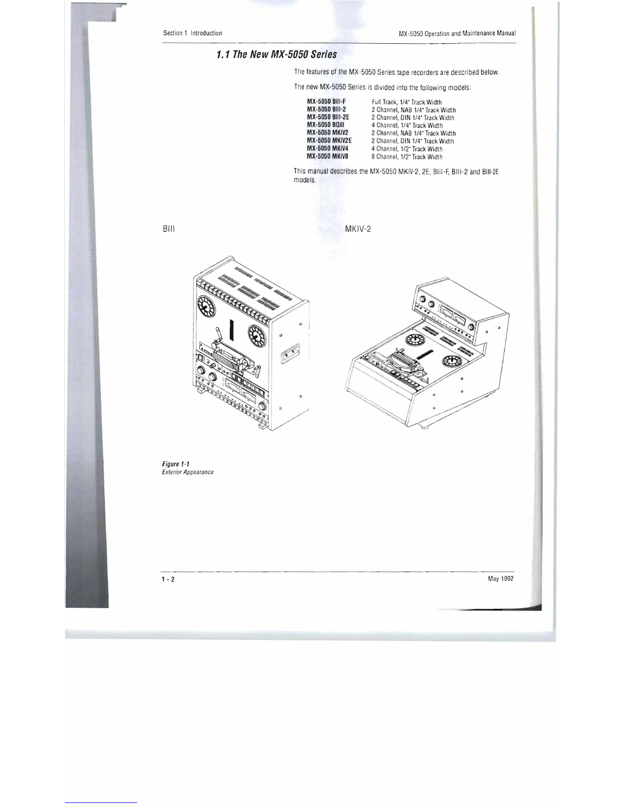
1.1
The
New
MX-5050
Series
The
features
of
the
MX-5050
Series
tape
recorders
are
described
below
.
The
new
MX-5050
Series
is
divided
int
o
the
following
models
:
MX-5050
BIH
Full
Track,
1/4'
Track
Width
Mx-5050
BIII-2
2
Channel,
NAB
1/4'
Track
Width
MX-5050
BIJI-2E
2
Channel,
DIN
1/4'
Track
Width
MX
-
5050
Balli
4
Channel,
1/4'
Track
Width
MX-5050
MKIV2
2
Channel,
NAB
1/4'
Track
Width
MX
-
5050
MKIV2E
2
Channel,
DIN
1/4'
Track
Width
Mx-5050
MKIV4
4
Channel,
1/2'
Track
Widt
h
MX-SOSO
MKIV8
8
Channel,
1/2'
Track
Width
This
manual
describes
the
MX-5050
MKIV
-2,
2E,
BIII-F,
BIII
-2
and
BIII
-2E
models
.
Bill
MKIV-2
Figure
1-1
Exterior
Appearance
1 - 2
May
1992

IOd
Maintenance
Manual
MX-5050
Operation
and
Maintenance
Manual
Section
1
Introduction
lescribed
below
.
odels:
111-2
and
BIII-2E
Fealures
o/Ihe
MX-5050
Series
In
addition
to
the
usual
tape
recorder
functions,
the
MX-5050
series
has
various
additional
features
.
All
MX-5050
series
tape
recorders
have
the
OTARI
Standard
Parallel
I/O
connector
which
allows
for
post
production
editing
work
with
a
synchronizer
using
time
code
.
The
tape
timers
include
a
Mini
Locator
for
more
advanced
locator
functions.
In
addition
to
these
functions,
these
machines
also
have
the
following
features:
Sel-Rep
(Selective
Reproduce),
Edit
mode
function
which
permits
tape
spilling,
CUE
monitoring
which
enables
monitoring
the
tape
in
F.FWO
or
RWO
mode,
Standby
function
for
easy
multi-channel
recording,
and
Variable
Pitch
Control
function
(±20%)
.
1.2
Using
This
Manual
1.2.1
Organization
This
manual
is
divided
into
ten
sections
as
follows.
Section
1
Introduction
This
section
describes
the
features
of
the
MX-5050
se
ries
tape
recorders
and
the
structure
of
this
manual.
Section
2
Installation
This
section
describes
the
procedures
for
unpacking
and
hooking
up
the
machine.
This
section
also
includes
the
01
P
sw
i
tch
presettings.
Section
3
Controls
and
Indicators
Thi
s
section
describes
the
name
and
function
of
each
control.
The
connector
pin
assignments
are
also
included
.
Section
4
Operation
This
section
explains
each
mode
of
the
mach
i
ne
and
the
basic
procedures
for
reproducing
and
recording
a
tap
e.
Section
5
Maintenance
This
section
describe
s
procedures
for
daily
maintenance.
May
1992
May
1992
Section
6
Transport
Adjustment
and
Parts
Replacement
This
section
describes
the
adjustment
procedures
for
transport
mechanisms
and
re
placement
procedures
.
Section
7
Audio
Alignment
This
section
describes
the
electr
i
cal
adjustment
of
the
Reproduce
and
Record
circu
i
ts
.
Section
8
Specllicalions
This
section
of
the
manual
contains
the
operating
specifications
for
MX
·
5050
ser
i
es
tape
recorders
.
Section
9
Exploded
Views
and
Parts
lists
This
section
of
the
manual
contains
assembly
drawings
of
the
machine
"ex
ploded
"
to
show
internal
parts
and
hardware
,
and
the
order
of
assembly.
Each
exploded
vi
ew
is
keyed
to
an
accompanying
parts
list
showing
OIarl
part
numbe
rs
and
descriptions
for
all
mechanical
components
.
1 - 3
Section
1
Introduction
MX·5050
Operation
and
Maintenance
Manual
Appendix
A
Block
Diagrams
Th
is
appendix
includes
block
di
agrams
of
the
MX·5050
and
level
diagrams
of
the
circuitry
Appendix
B
Troubleshooting
This
section
describes
some
typical
problems
which
may
occur
during
operations,
their
possible
causes
and
how
to
handle
them
.
1.2.2
Conventions
within
this
manual
PCB
Assemblies:
The
term
PCB
Assembly
is
used
in
this
manual
to
refer
to
a
printed
circuit
board
which
has
components
(resistors,
connectors,
etc.)
mounted
on
it.
The
term
PCB
or
Pr
i
nted
Circuit
Board,
when
used
alone
refers
to
the
"bare
'·
printed
circuit
board
without
components
.
The
term
PCB
is
rarely
used
outside
of
the
electrical
and
mechanical
parts
lists
.
When
a
PCB
Assembly
is
referred
to
in
the
text,
the
name
or
function
of
that
PCB
Assembly
will
usually
be
given
in
ALL
CAPITAL
letters
Type
conventions
ALL
UPPER
CASE·
Generally,
this
manual
uses
all
upper
case
type
to
descr
i
be
a
switch
or
control
when
that
item
is
similarly
labeled
on
the
machine
(e
.g.,
the
PLAY
button)
.
First
Letter·
Where
a
switch
or
button
is
not
Upper
Case
labeled
,
or
the
reference
is
less
clear,
only
the
first
letter
of
the
item
is
capitalized
(e
.g
.,
the
Cue
Wheel
near
the
CUE
button)
.
Machine
status
or
operating
modes
are
described
with
an
upper
case
first
letter
(e
.g
.,
you
press
the
PLAY
button
to
place
the
machine
in
Play
mode)
.
(
),
[ ] .
Normal
parentheses
( )
are
used
for
examples
and
parenthetic
comments.
Square
brackets
[ ]
are
used
to
refer
to
certain
illustrations
.
When
used
in
te
xt,
the
square
brackets
are
either
references
to
the
same
figure
as
noted
in
that
sub'section
(e
.g,
[3],
meaning
the
part
labeled
"
3"
in
the
figu
re
noted)
or
are
preceded
by
the
fi
gure
number
(e
.g
.,
Fig.
2-1,
[3),
meaning
'3"
in
Figure
2-
1)
.
May
1992
1 - 4
Id
Maintenance
Manual
nd
level
diagrams
of
occur
during
manual
to
refer
to
a
'
nnectors,
etc.}
en
used
alone
ltS.
The
term
PCB
s
lists.
When
a
on
of
that
PCB
:ase
type
to
eled
on
the
abeled,
or
the
·italized
(e.g.,
the
ing
modes
are
3
PLAY
button
to
parenthetic
Ilustrations.
When
3
same
figure
as
j
"3
"
in
the
figure
[3J,
meaning
"3"
Section
2
Installation
This
section
of
the
manual
provides
information
on
unpacking
and
inspecting
the
tape
recorder,
and
on
power
and
signal
connections.
Refer
to
this
section
when
first
setting
up
the
machine.
This
section
includes
the
following
sub
sections.
2.
1
Unpacking
and
Inspection
... ... .
....
.... ... .
....
...
2-2
2.2
Audio
Signal
Connection
..
... ..
.....
......
.....
..
....
....
2-3
2.2.1
Audio
Connectors
.
..
. .
....
....
.....
..
.........
.
...
2-3
2.2.2
Balance/Unbalance
Adjustment
. . ... ... .. .. ..
...........
..
..
.
2-4
2.3
Switch
Position
Adjustment
... ...... ....... .....
..
........
..
.....
2-5
2.4
PCB
Assembly
Location
............
2-9
2.4
.1
MX-5050
Bill
.....
........
2-9
2.4
.2
MX·5050
MKIV2
...... .
.......
....
..
2-11
2.5
Power
Connection
.
.................
2-13
.
2.6
Fuse
Replacement
.
..........
.. ...
....
2-14
2.7
Speed
Conversion
(BIII-2)
. .
.......
.....
2-15
2.8
Equalizer
Change
..
... ....
...
.. ...
2-15
May
1992
2-1
May
1992

Section
2
Installation
MX-SOSO
Operation
and
Maintenance
Manual
2.1
Unpacking
and
Inspection
Table
2-1
Standard
Accessories
After
receiving
the
MX-5050,
examine
the
case
for
any
signs
of
damage
.
Then
unpack
and
inspect
the
equipment.
Take
care
when
unpacking
the
equipment
and
removing
packing
materials
to
prevent
damaging
the
critical
components
such
as
the
capstan,
head
assembly,
and
tension
arms.
If
there
is
any
evidence
of
damage
due
to
rough
handling
during
transportation,
a
claim
should
be
filed
with
the
transportation
company
.
We
recommend
retain
i
ng
the
packing
material
at
least
until
proper
operation
of
the
machine
has
been
established.
Verify
that
all
items,
as
listed
in
Table
2-1,
have
been
received.
Do
not
connect
or
operate
the
MX-5050
until
this
inspection
has
been
completed
.
When
send
in
g
the
machine
back
to
the
local
OTARI
dealer
or
to
OTARI,
follow
the
packing
directions
printed
on
the
carton.
MX-5050
Bill,
MKIV·2
Parts
Name
Part
No
.
Quantity
Reel
Clamp
KWOHV
2
Power
Cable
PZ9DOO3
1
Manual
OS3-
2
98
1
Lubr
ication
Oi
l
PZ9EOO3
1
Fuse
1A
FH7F010
1
(Fuse
1A
200·240V
only
FH9·032
1)
Fu
se
2A
FH9-030
1
Fu
se
2A
FH7F020
1
Fuse
3A
FH7F030
1
Fuse
4A
FH7F040
1
Fuse
SA
FH7FOSO
1
May
1992
2-2
<
and
Maintenance
Manual
;igns
of
damage.
n
unpacking
the
l
amaging
the
critical
lnsion
arms.
If
there
I
transportation,
a
Ve
recommend
tion
of
the
machine
:eived.
Do
not
;
been
com
pleted.
lr
or
to
OTARI,
follow
MX-5050
Operation
and
Maintenance
Manual
Section
2
Installation
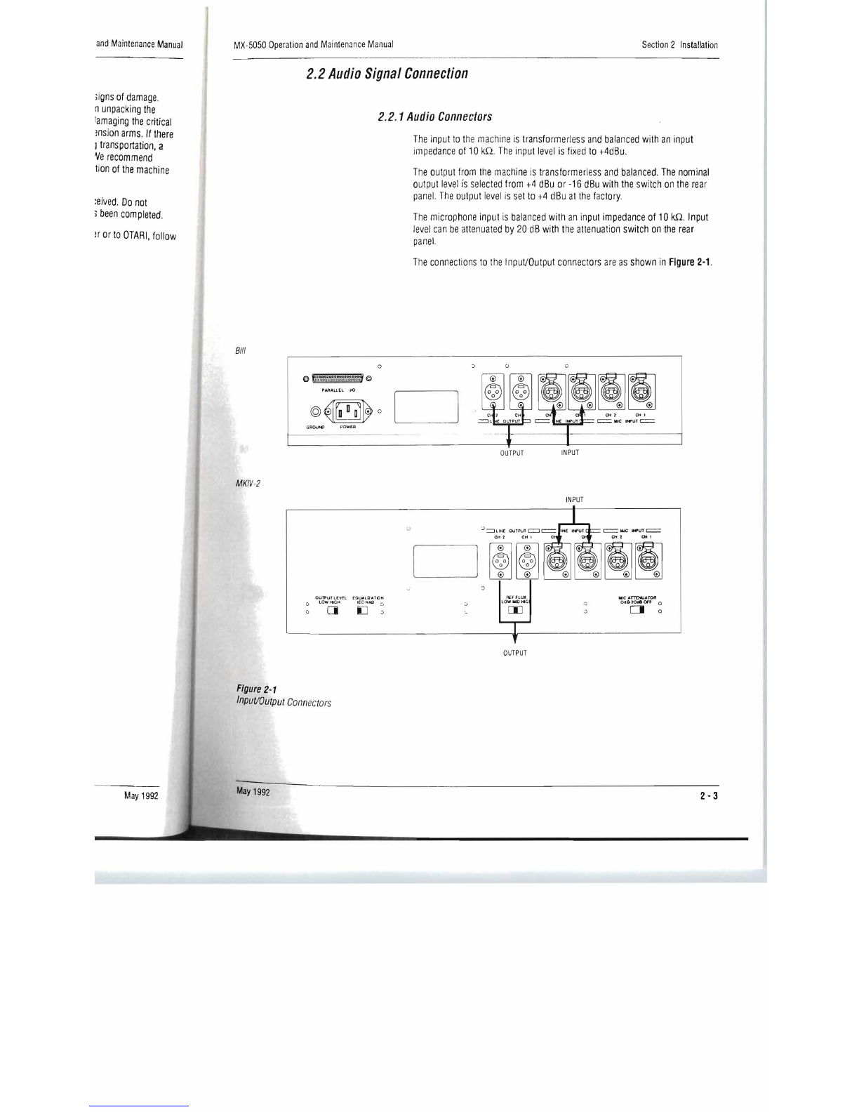
2.2
Audio
Signal
Connection
2.2.1
Audio
Connectors
Bill
0
@
f,
'iii&
·
l
iiaai~
~
@
PARALlEL
110
@~rD
D
D
l
~
0
GAOUO" POWER
MKIV-2
The
input
to
the
machine
is
transformerless
and
balanced
with
an
input
impedance
of
10
kil.
The
input
level
is
fixed
to
+4dBu
.
The
output
from
the
machine
is
transformerless
and
balanced.
The
nominal
output
level
IS
selected
from
+4
dBu
or
-16
dBu
with
the
switch
on
the
rear
panel.
The
output
level
is
set
to
+4
dBu
at
the
factory.
The
microphone
input
is
balanced
with
an
input
impedance
of
10
kn.
Input
level
can
be
attenuated
by
20
dB
with
the
attenuation
switch
on
the
rear
panel.
The
connections
to
the
InpuVOutput
connectors
are
as
shown
in
Figure
2-1.
:,
D " 0 .
J~II~I
"',
""
OUTP
UT
INPUT
INPUT
CH'
"',
'"
,
D 0
0
~
~
.
~~
0
~®
0
0 0 0
~
OUTPUJ
LEVEL
EQWUZA
lION
REf
flUX
"C
ATT£HUATOR
LOW
HleH
lEe
NAi;l LOWMlO~C;
0C1&20QII
Off
a
:0
0 0 ~
0
[j
~
[j]
C1
0
iJ
OUTPUT
Figure
2-1
Input/Output
Connectors
May
1992
May
1992
2- 3

Section
2
Installation
MX-SOSO
Operation
Jnd
Maintenance
Manual
2-2.2
Balanced/Unbalanced
Connection
The
InpuVOutput
connectors
are
balanced
as
shown
in
Figure
2-2.
The
pin
assignment
of
the
connectors
is
as
follows:
Pin
1
Shield
(GNO)
Pin
2
Cold
Pin
3
Hot.
When
connecting
an
unbalanced
machine
to
the
MX-5050,
change
the
pin
assignment
as
shown
in
Figure
2-2.
Balanced Input Balanced Output
Unbalanced
Input
Unbalanced Output
Figure
2-2
Optional
Input
(ZA-53T)
/O
utput
(ZA-53S)
Transformers
are
available
from
Balanced/Unbalanced
Connectors
OTARI.
For
details
contact
OTARt
or
your
nearest
OTARI
dealer.
2-4
May
1992
cd
Jnd
Maintenance
Manual
Figure
2-2,
The
pin
50,
change
the
pin
Jut
)utput
available
from
aler.
May
1992
MX-SOSO
Operation
and
Maintenance
Manual
Section
2
Installation
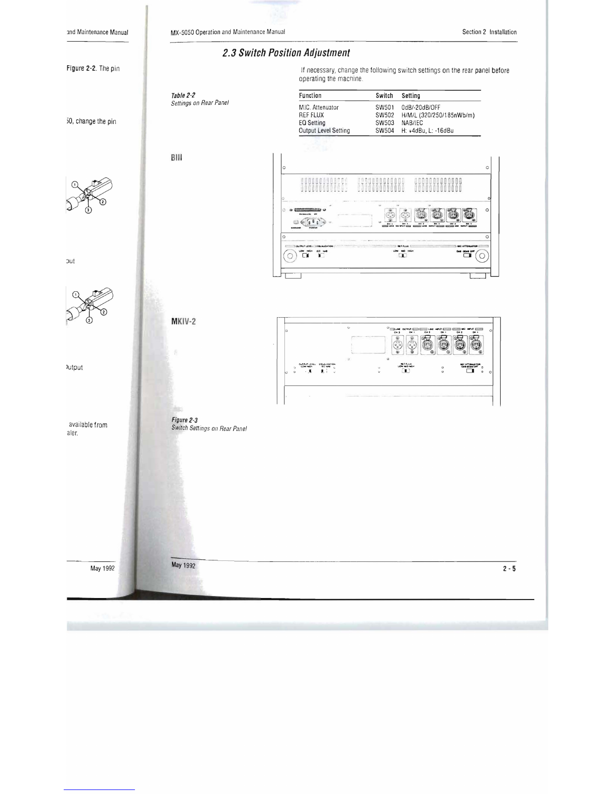
2.3
Switch
Position
Adjustment
If
necessary,
change
the
following
switch
settings
on
the
rear
panel
before
operating
the
machine
.
Table
2-2
Function
Switch
Selling
Settings
on
Rear
Panel
M
IC
.
Attenuator
SWSOI
OdB/-20dB/OFF
REF
FLUX
SWS02
H/M/L
(320/2S0/18SnWb/m)
EO
Setting
SWS03
NAB/IEC
Output
Level
Setting
SWS04
H:
+4dBu,
L:
-16dBu
Bil
l o o
_ u •
_ , :@
I'
@I
~
,
~rr
~fSl
0
o
.~
-
.
~
~
.
~
r_.t
il
L
~~
~
=--
-
......
~
==--
-.~~--~
o o
c,
\ _
....
"'-
LJ Jo '
"'o
@
M
KIV-2
~
v
c;..n.,n
"
",
.
.,
-~
u ...
~
(0
.....
·'-&10-
1
((""'"
C
,-: ,
v
,
.
--
,
U
~UOOI
o.II,Inc=Jc::=
........
ittI'lAC:=::>c=I.o
W\II't:::::j
'"'
~,
'"'
~,
'"'
"',
~~
~~~~
I @ @i
-.J
I; ; ® 0
cv
@
Q
..
~
,.v.
..c:"n_~
"
LOW.a..:;:
.. 0
......
....
0
u =IJ 0
CJ
0
0
0
--- -
--
Figure
2·3
Switch
Settings
on
Rear
Panel
May
1992
2- 5
Table of contents
Other OTARI Recording Equipment manuals

OTARI
OTARI MX-5050 BII Series User manual

OTARI
OTARI MX-50II Series User manual

OTARI
OTARI MX-505MKIII-2 User manual

OTARI
OTARI MTR-10II Series User manual

OTARI
OTARI MX-55T-M User manual

OTARI
OTARI MX-5050 User manual

OTARI
OTARI MTR-90III User manual

OTARI
OTARI MX-5050 Manual

OTARI
OTARI MX-5050BII Series User manual

OTARI
OTARI MX 5050 BQII Series User manual


Popular Recording Equipment manuals by other brands


JLCooper Electronics
JLCooper Electronics MCS6 USB user manual

ABB
ABB EP010 User's and operator's manual

Tigertronics
Tigertronics SignaLink Installation & operation

Ei Electronics
Ei Electronics Ei414 instruction manual

MORLEY PEDALS
MORLEY PEDALS POB2 manual

nuance hearing
nuance hearing Voice Selector Study user guide