OTC DAIHEN EUROPE CM-741 User manual
MANUAL NO: U5278
OWNER'S MANUAL
FOR
WIRE FEEDER
MODEL: CM-741 U5278
DO NOT DESTROY
IMPORTANT: Read and understand the entire contents of this
manual, with special emphasis on the safety material throughout
the manual, before installing, operating, or maintaining this
equipment. This equipment and this manual are for use only by
persons trained and experienced in the safety operation of welding
equipment. Do not allow untrained persons to install, operate or
maintain this equipment. Contact your distributor if you do not
fully understand this manual.
DAIHEN Corporation WELDING PRODUCTS DIVISION May 19, 2004
Upon contact, advise MODEL and MANUAL
NO.

Notice : Machine export to Europe
This product does not meet the requirements specified in the EC Directives which are the EU safety
ordinance that was enforced starting on January 1, 1995. Please make sure that this product is not
allowed to bring into the EU after January 1, 1995 as it is.
The same restriction is also applied to any country which has signed the EEA accord.
Please ask us before attempting to relocate or resell this product to or in any EU member country or
any other country which has signed the EEA accord.

No. U5278
―1―
TABLE OF CONTENTS
1. SAFETY INFORMATION・・・・・・・・・・・・・・・・・・・・・・・・・・・・・・・・・・・・・・・・・・・・・・・・・・・・・・・・・・ 2
2. ARC WELDING SAFETY PRECAUTIONS・・・・・・・・・・・・・・・・・・・・・・・・・・・・・・・・・・・・・・・・・・・ 2
3. CHECKING OF QUANTITY OF THE ACCESSORIES・・・・・・・・・・・・・・・・・・・・・・・・・・・・・・・・・・ 8
4. NAME OF PARTS・・・・・・・・・・・・・・・・・・・・・・・・・・・・・・・・・・・・・・・・・・・・・・・・・・・・・・・・・・・・・・・・・8
5. CARRYING AND INSTALLING OF THE WIRE FEEDER・・・・・・・・・・・・・・・・・・・・・・・・・・・・・・・・ 9
6. CONNECTION PROCEDURE・・・・・・・・・・・・・・・・・・・・・・・・・・・・・・・・・・・・・・・・・・・・・・・・・・・・・・・ 10
7. WELDING PREPARATION・・・・・・・・・・・・・・・・・・・・・・・・・・・・・・・・・・・・・・・・・・・・・・・・・・・・・・・・・ 13
8. MAINTENANCE AND TROUBLESHOOTING・・・・・・・・・・・・・・・・・・・・・・・・・・・・・・・・・・・・・・・・・・ 18
9. PARTS LIST・・・・・・・・・・・・・・・・・・・・・・・・・・・・・・・・・・・・・・・・・・・・・・・・・・・・・・・・・・・・・・・・・・・・・・ 20
10. SPECIFICATIONS・・・・・・・・・・・・・・・・・・・・・・・・・・・・・・・・・・・・・・・・・・・・・・・・・・・・・・・・・・・・・・・・・27
No. U5278
―2―
1. SAFETY INFORMATION
The following safety alert symbols and signal words are used throughout this manual to
identify various hazards and special instructions.
WARNING WARNING gives information regarding possible personal injury
or loss of life.
CAUTION CAUTION refers to minor personal injury or possible equipment
damage.
2. ARC WELDING SAFETY PRECAUTIONS
WARNING
ARC WELDING can be hazardous.
PROTECT YOURSELF AND OTHERS FROM POSSIBLE SERIOUS INJURY OR DEATH.
Be sure to:
・Keep children away.
・Keep pacemaker wearers away until consulting a doctor.
Read and understand the summarized safety information given below and the original
principal information that will be found in the PRINCIPAL SAFETY STANDARDS.
Have only trained and experienced persons perform installation, operation, and
maintenance of this equipment.
Use only well maintained equipment. Repair or replace damaged parts at once.
ARC WELDING is safe when precautions are taken.
No. U5278
―3―
2. ARC WELDING SAFETY PRECAUTIONS (continued)
ELECTRIC SHOCK can kill.
Touching live electrical parts can cause fatal shocks or severe burns. The electrode and work
circuits are electrically live whenever the output is on. The power line and internal circuits of
this equipment are also live when the line disconnect switch is on. When arc welding all metal
components in the torch and work circuits are electrically live.
1. Do not touch live electrical parts.
2. Wear dry insulating gloves and other body protection that are free of holes.
3. Insulate yourself from work and ground using dry insulating mats or covers.
4. Be sure to disconnect the line disconnect switch before installing, changing torch parts
or maintaining this equipment.
5. Properly install and ground this equipment according to its Owner’s Manual and national,
state, and local codes.
6. Keep all panels and covers of this equipment securely in place.
7. Do not use worn, damaged, undersized, or poorly spliced cables.
8. Do not touch electrode and any metal object if POWER switch is ON.
9. Do not wrap cables around your body.
10. Turn off POWER switch when not in use.
ARC RAYS can burn eyes and skin: FLYING SPARKS AND HOT METAL can
cause injury. NOISE can damage hearing.
Arc rays from the welding process produce intense heat and strong ultraviolet rays that can
burn eyes and skin.
Noise from some arc welding can damage hearing.
1. Wear face shield with a proper shade of filter (See ANSI Z 49.1 listed in PRINCIPAL
SAFETY STANDARDS) to protect your face and eyes when welding or watching a welder
work.
2. Wear approved safety goggles. Side shields recommended.
3. Use protective screens or barriers to protect others from flash and glare: warn others not
to look at the arc.
4. Wear protective clothing made from durable, flame-resistant material (wool and leather)
and foot protection.
5. Use approved earplugs or earmuffs if noise level is high.
Chipping and grinding can cause flying metal. As welds cool, they can throw off slag.
6. Wear approved face shield or safety goggles. Side shields recommended.
7. Wear proper body protection to protect skin.
No. U5278
―4―
2. ARC WELDING SAFETY PRECAUTIONS (continued)
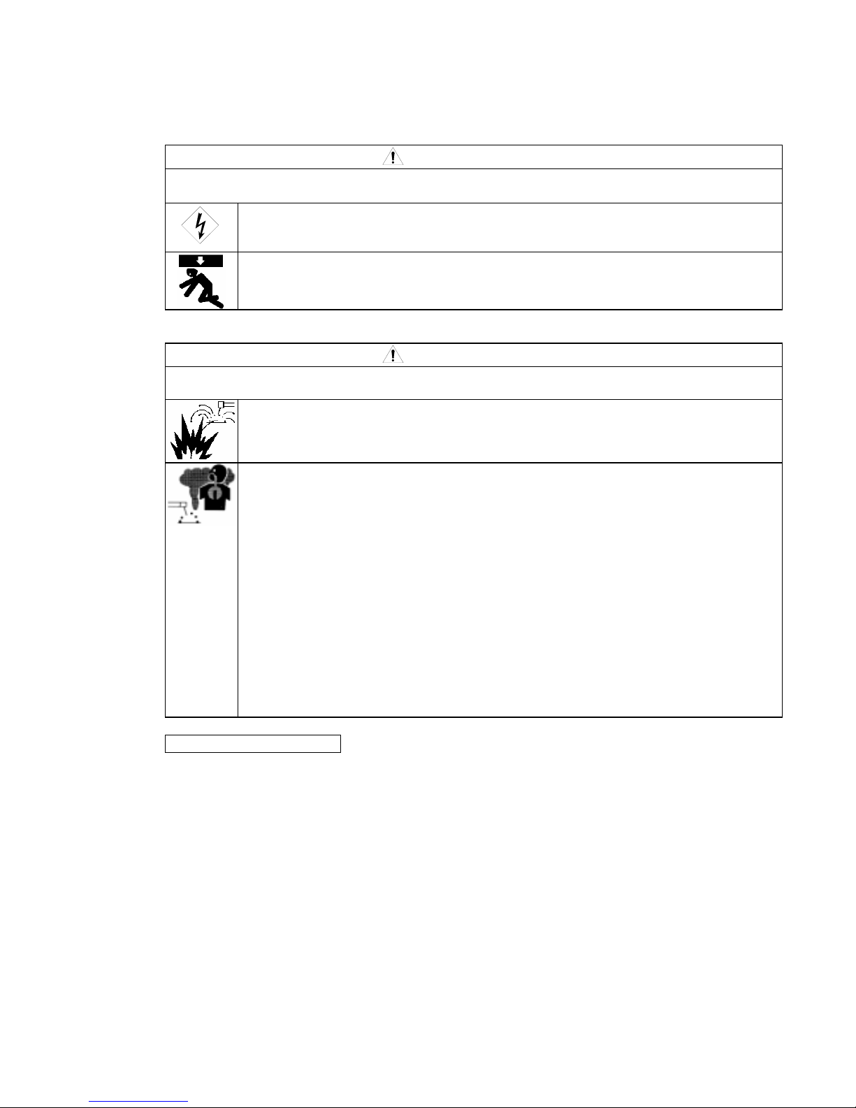
WELDING can cause fire and explosion.
Sparks and spatter fly off from the welding arc. The flying sparks and hot metal, spatter, hot
base metal, and hot equipment can cause fire and explosion. Accidental contact of electrode or
welding wire to metal object can cause sparks, overheating, or fire.
1. Protect yourself and others from flying sparks and hot metals.
2. Do not weld where flying sparks can strike flammable material.
3. Remove all flammables within 10m (33ft) of the welding arc. If this is not possible, tightly,
cover them with approved covers.
4. Be alert that welding sparks and hot metals from welding can easily pass through cracks
and openings into adjacent areas.
5. Watch for fire, and keep a fire extinguisher nearby.
6. Be aware that welding on a ceiling, floor, bulkhead, or partition can ignite a hidden fire.
7. Do not weld on closed containers such as tanks or drums.
8. Connect base metal side cable as close to the welding area as possible to prevent the
welding current from traveling along unknown paths and causing electric shock and fire
hazards.
9. Remove stick electrode from holder or cut off welding wire at contact tip when not in use.
10. Does not use the welding power source for other than arc welding.
11. Wear oil-free protective garments such as leather gloves, a heavy shirt, cuffless trousers,
boots, and a cap.
12. A loose cable connection can cause sparks and excessive heating.
13. Tighten all cable connections.
14. When there is an electrical connection between a work piece and the frame of wire feeder
or the wire reel stand, are may be generated and cause damage by a fire if the wire contacts
the frame or the work piece.
FUMES AND GASES can be hazardous to your health.
Arc welding produce fumes and gases. Breathing these fumes and gases can be hazardous to
your health.
1. Keep your head out of the fumes. Do not breathe the fumes.
2. Ventilate the area and/or use exhaust at the arc to remove welding fumes and gases.
3. If ventilation is poor, use an approved air-supplied respirator.
4. Read the Material Safety Data Sheets (MSDS) and the manufacturer’s instructions on
metals, consumables, coatings, and cleaners.
5. Do not weld or cut in locations near degreasing, cleaning, or spraying operations.
The heat and rays of the arc can react with vapors to form highly toxic and irritating gases.
6. Work in a confined space only if it is well ventilated, or while wearing an air-supplied
respirator. Shielding gases used for welding can displace air causing injury or death.
Be sure the breathing air is safe.
No. U5278
―5―
2. ARC WELDING SAFETY PRECAUTIONS (continued)
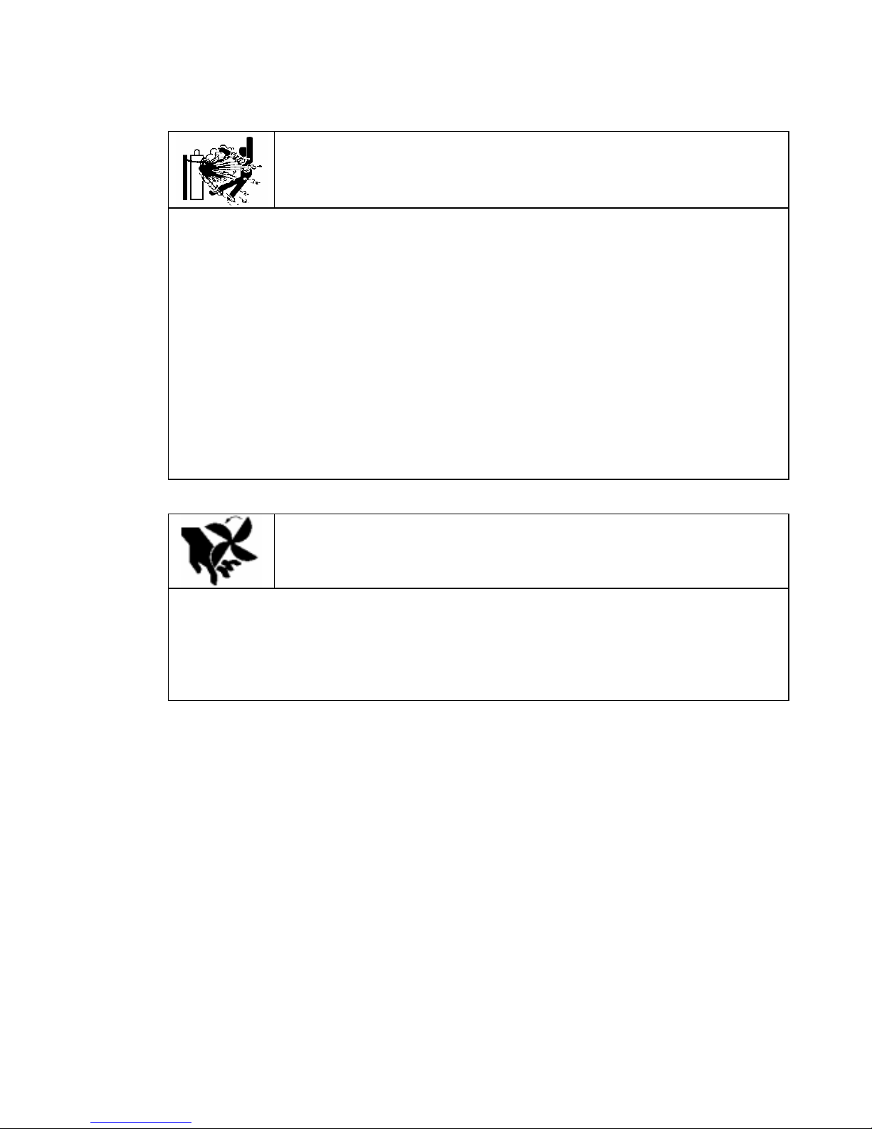
CYLINDER can explode if damaged.
A shielding gas cylinder contains high-pressure gas. If damaged, a cylinder can explode.
Since gas cylinders are normally part of the welding process, be sure to treat them carefully.
1. Use only correct shielding gas cylinders, gas regulator, hoses, and fittings designed for the
specific application; maintain them in good condition.
2. Protect compressed gas cylinders from excessive heat, mechanical shock, and arcs.
3. Keep the cylinder upright and securely chained to a stationary support or a rack to prevent
falling or tipping.
4. Keep cylinders away from any welding or other electrical circuit.
5. Never touch cylinder with welding electrode.
6. Read and follow instructions on compressed gas cylinders, associated equipment, and the
CGA publication P-1 listed in PRINCIPAL SAFETY STANDARDS.
7. Turn face away from valve outlet when opening cylinder valve.
8. Keep protective cap in place over valve except when gas cylinder is in use or connected for
use.
9. Do not disassemble or repair the gas regulator except for the person authorized by the
manufacturer of them.
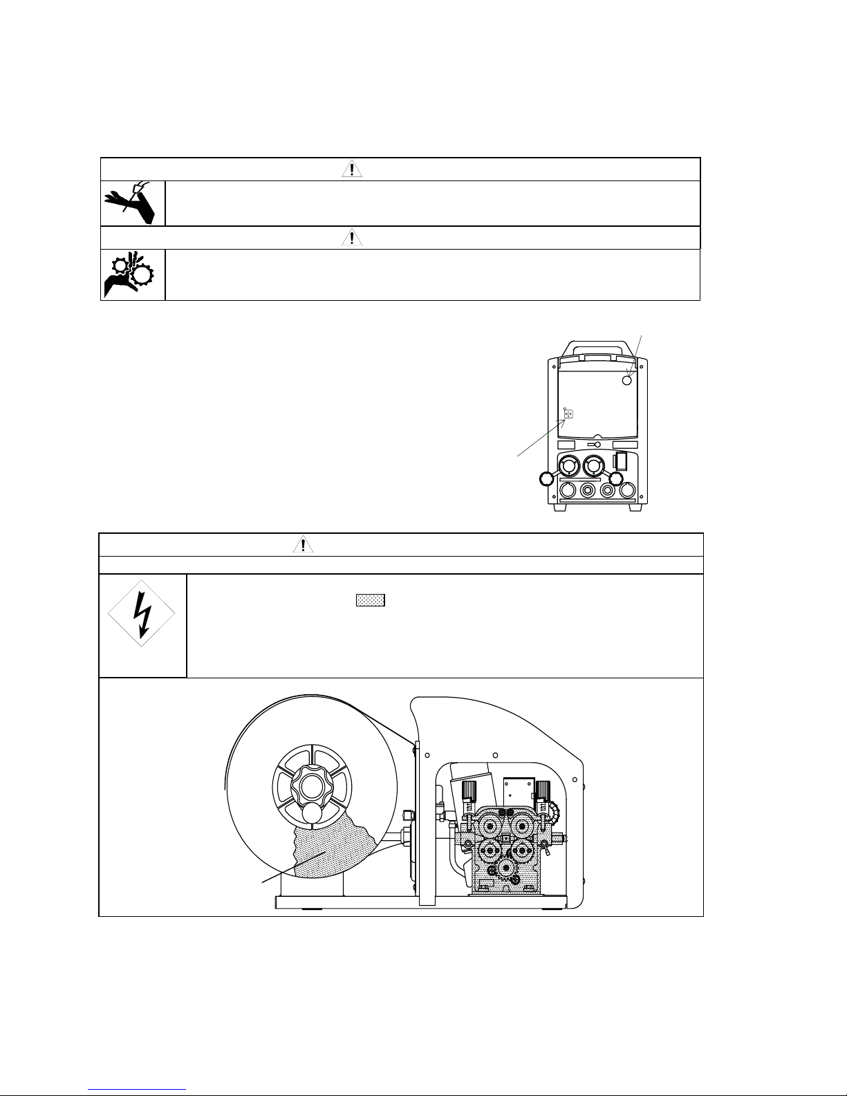
Rotating parts may cause injuries. Be sure to observe the following.
If hands, fingers, hair or clothes are put near the fan’s rotating parts or wire feeder’s feed roll,
injuries may occur.
1. Do not use this equipment if the case and the cover are removed.
2. When the case is removed for maintenance/inspection and repair, certified or experienced
operators must perform the work. Erect a fence, etc. around this equipment to keep others
away from it.
3. Do not put hands, fingers, hair or clothes near the rotating fans or wire feed roll.

No. U5278
―6―
2. ARC WELDING SAFETY PRECAUTIONS (continued)
ARC WELDING work areas are potentially hazardous.
FALLING or MOVING machine can cause serious injury.
When hanging the welding power source by a crane, do not use the carrying handle.
Put the welding power source and wire feeder solidly on a flat surface.
Do not pull the welding power source across a floor laid with cables and hoses.
Do not put wire feeder on the welding power source.
Do not put the welding power source and wire feeder where they will pit or fall.
WELDING WIRE can cause puncture wounds.
Do not press gun trigger until instructed to do so.
Do not point gun toward any part of the body, other people, or any metal when threading
welding wire.

No. U5278
―7―
PRINCIPAL SAFETY STANDARDS
Arc welding equipment – Installation and use, Technical Specification
IEC 62081, from International Electro technical Commission
Arc welding equipment Part 1: Welding power sources IEC 60974-1, from International Electro
technical Commission
Safety in Welding and Cutting, ANSI Standard Z49.1, from American Welding Society.
Safety and Health Standards, OSHA 29 CFR 1910, from Superintendent of Documents, U.S.
Government Printing Office.
Recommended Practices for Plasma Arc Cutting, American Welding Society Standard AWS C5.2,
from American Welding Society.
Recommended Safe Practices for the Preparation for Welding and Cutting of Containers That Have
Held Hazardous Substances, American Welding Society Standard AWS F4.1, from American
Welding Society.
National Electrical Code, NFPA Standard 70, from National Fire Protection Association.
Safe Handling of Compressed Gases in Cylinders, CGA Pamphlet P-1, from Compressed Gas
Association.
Code for Safety in Welding and Cutting, CSA Standard W117.2, from Canadian Standards
Association, Standards Sales.
Safe Practices For Occupation And Educational Eye And Face Protection, ANSI Standard Z87.1,
from American National Standards Institute.
Cutting And Welding Processes, NFPA Standard 51B, from National Fire Protection Association.
NOTE: The codes listed above may be improved or eliminated. Always refer to the updated codes.
M040521

No. U5278
―8―
3. CHECKING OF QUANTITY OF THE ACCESSORIES
Make sure that you have the items below before you use the wire feeder.
Wire feeder
Wire feeder Accessory
4. NAMES OF PARTS
Refer to the section indicated in for details.
No. Description Specification Quantity
①Gas hose (9.8ft [3m]) K5430A00 1
②Hose cover U1997C03 2
③Cable joint 4734-027 1
Pressure handles
Wire reel hub
Frame
Torch socket
Feed rolls
Control cable 10P
Feed motor
Pressure roll holder
6.3
7.2
7.2
8.1
Gas supply inlet 6.4
7.1 7.3
Gas connecting fittings
No. U5278
―9―
5. CARRYING AND INSTALLING OF THE WIRE FEEDER
5.1 Transportation
WARNING
Observe the following to avoid damage to the wire feeder or physical injury when carrying the
equipment.
● Do not touch the charging parts inside or outside of the wire feeder.
● Disconnect the welding power source by turning off the line disconnect switch in
the power box to avoid an electric shock before carrying the equipment.
● Be sure to detach the wire reel from the fire feeder before lifting the equipment to
the high places by a crane.
5.2 Installation
WARNING
When installing the wire feeder, follow the instructions below to avoid occurrence of fires during
welding and physical damage by fume gas.
● Do not place the welding machine near combustible materials and flammable gas.
● Remove combustible materials to prevent dross coming into contact with
combustible objects. If that not possible, cover them with noncombustible covers.
● To avoid gas poisoning and danger of suffocation, wear a gas mask or adequately
ventilate when using the welding machine in the place regulated by a local law.
● To prevent disorder or poisoning caused by fume, wear a gas mask or weld at a
partial exhaust facility approved by the local regulation.
● Adequately ventilate or wear a gas mask when using the welding machine in a
tank, a boiler, a hold of a ship, because heavier gas such as carbon dioxide or
argon gases are drifting there.
● When using the welding machine at a narrow space, comply with a trained
supervisor’s directions. And be sure to wear a gas mask.
● Do not operate the welding machine near the place where degreasing, cleansing,
and spraying are performed. Otherwise, poisonous gas may be generated.
● Be sure to wear a gas mask or adequately ventilate when welding a coating steel
plate. (Poisonous gas and fume may be generated.)
● Do not place the welding power source, wire feeder, torch, and control cable
(including the extension cable) in an area where the equipment can become wet.
INSTALLATION PLACE
Follow the instructions below when selecting an installation place of the wire feeder.
● Do not install the wire feeder in the indoor place subject to direct sunlight and rain.
● Install the wire feeder in the place where the ambient temperature is between -10 ˚C and +40
˚C.
● Do not place the welding power source, wire feeder, torch, and control cable (including the
extension cable) in an area where the equipment can become wet.
● Use a wind shield to protect arc from a wind blow when welding on a windy day.
No. U5278
―10―
6. CONNECTION PROCEDURE
CAUTION
Follow the instructions below to avoid electric shock.
∗Do not touch the charging parts, otherwise this will result in fatal shock and severe burns.
● Do not touch the charging parts of the welding machine.
● Have a qualified electric engineer ground the case of the welding power source and the base
metal or jig electrically connected, following a local low.
● Disconnect the welding power source by turning off the line disconnect switch in the power
box to avoid an electric shock before grounding the welding power source or base metal and
connecting the cables or hoses.
● Do not use a cable with lack of capacity or a cable seriously damaged.
● Tighten and insulate the connections of cables.
●
Firmly attach the cover of the welding machine after connection of the cables.
●
Do not place the welding power source, wire feeder, torch, and control cable (including the
extension cable) in an area where the equipment can become wet.
6.1 Connecting to the Welding Power Source and to the Gas regulator
Standard Composition
NOTE: Standard composition consists of the parts indicated in . Preparation of the
parts except the standard composition is required to use the wire feeder.
*Available in 16ft [5m], 33ft [10m], 49ft [15m], and 66ft [20m].
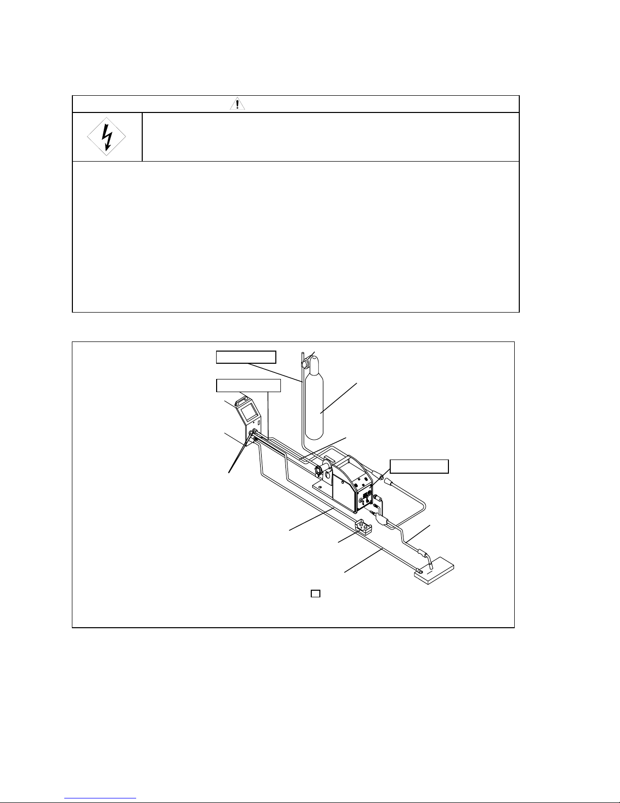
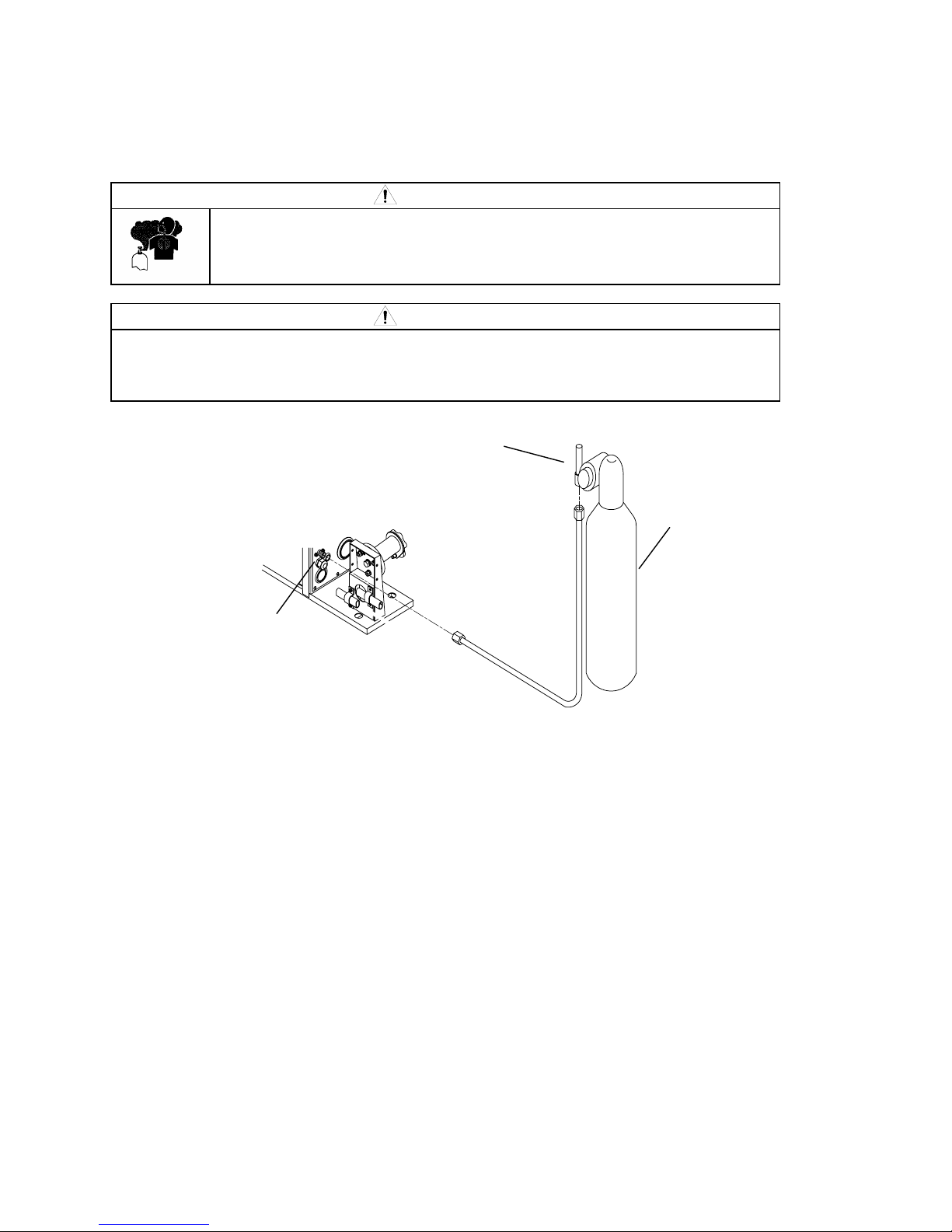
Follow the steps below to connect to the welding power source and to the gas regulator.
1. Ground the base metal (if required by local laws or codes).
2. Connect between the negative output terminal for the base metal and the base metal with the base metal
cable.
3. Attach the torch cable to the positive output terminal of the welding power source.
4. Plug the control cable for the wire feeder (10P) into the wire feeder socket on the welding power source.
5. Attach the gas hose to the gas supply inlet on the wire feeder.
6. Connect the welding torch to the wire feeder.
7. Connect the torch cable to the power cable of the welding torch.
Welding
power
source
Wire feeder
Base metal cable*
Welding torch
Remote control cable
Gas hose*
Gas cylinder
Remote control
(
O
p
tional
)
Firmly attach the DINSE connectors
by turning the connectors in the
clockwise direction.
Gas regulator
Control cable
Torch cable*
No. U5278
―11―
6. CONNECTION PROCEDURE (continued)
6.2 Connection of the Torch Cable
WARNING
∗Touching the charging parts may result in fatal electric shock and severe burns.
● Do not touch the charging parts of the welding machine.
● Have a qualified electric engineer ground the case of the welding power source and the base
metal or jig electrically connected in accordance with a local low.
● Disconnect the welding power source by turning off the line disconnect switch in the power
box to avoid an electric shock before the welding power source or base metal and connecting
the cables or hoses.
● After connecting the cables, cover the power source with the cover or case.
● When using the welding machine in such a humid environment as construction site, on the
steel plate, or on steel structure, install a leakage breaker.
CAUTION
● Use the proper torch cable that matches the welding current.
Welding current Cable thickness
200 A AWG 1 [38mm2] or more
350 A AWG 0 [60mm2] or more
500 A AWG 3/0 [80mm2] or more
* When performing pulse welding using a 56ft [17m] or more cable, use the thicker cable by one
rank.
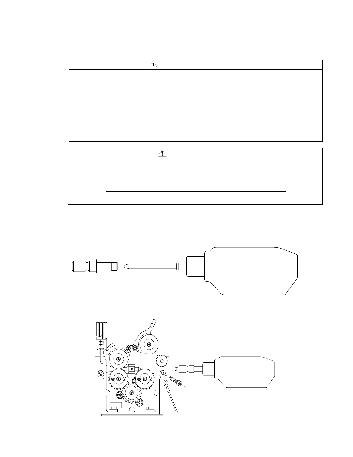
6.3 Connection of the welding torch
1. Remove the guide adapter from the wire feeder, insert the outlet guide into the guide adapter and
attach the guide adapter to the conduit of the welding torch. Use proper sized outlet guide adjusted
to the wire size.
2. Insert the guide adapter to the
Guide Adapter Outlet Guide
Welding Torch
Bolt (M6)
No. U5278
―12―
6. CONNECTION PROCEDURE (continued)
6.4 Connection of the Gas Hose
WARNING
●
Y
ou may suffer from danger of suffocation caused by lack of oxygen when
shield gas keeps drifting in a closed place. Be sure to turn off the shield gas
at the main when the welding power source is not in use.
WARNING
● Be sure to connect the gas hose after fixing to the stand, as physical injuries may result
from falling down of gas cylinder.
● Attach a proper gas regulator to the gas cylinder. Failure to observe the demand may result
in physical injuries. The gas regulator for high pressure gas must be used.
Follow the steps below to connect to the gas regulator.
1. Firmly connect the gas hose to the gas supply inlet located on the rear side of the wire feeder.
2. Mount the gas regulator on the gas cylinder by tightening the nut for attaching the gas cylinder .
3. Connect the gas hose to the gas supply outlet on the gas regulator.
NOTE: Firmly tighten the nuts using a monkey wrench, etc. to connect the gas hose and gas
regulator.
Gas cylinder
Gas regulator
Gas inlet
No. U5278
―13―
7. WELDING PREPERATION
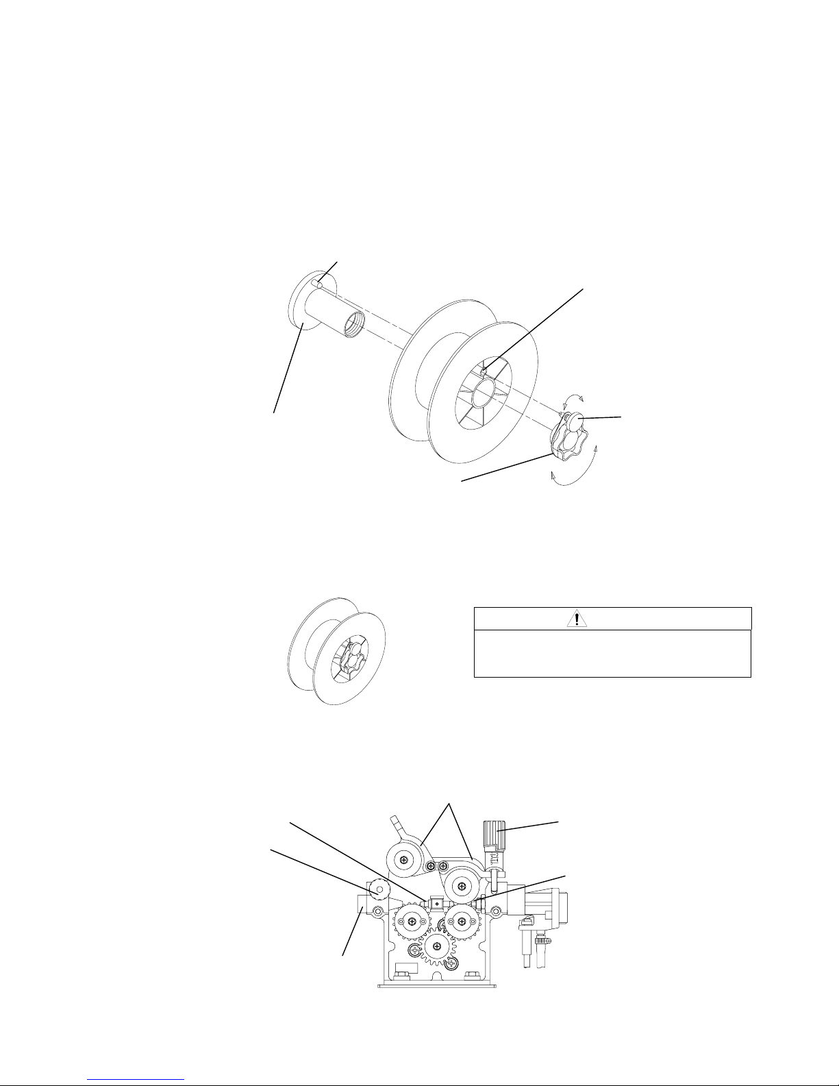
7.1 Fitting of Wire
1. Loosen the screw to clamp the cap knob.
2. Detach the cap knob from the wire reel shaft.
3. Mount the wire reel on the wire reel shaft.
NOTE: Put the wire reel stop pin into the wire reel stop hole.
4. Firmly tighten the cap knob.
5. Align the hole in the cap knob with the wire reel stop hole, then fasten the clamp screw to
prevent the cap knob from dropping.
6. Bring down the pressure handle, then raise the pressure roll holder.
7. After pulling out the wire, thread it from the pilot to outlet guide through the center guide.
8. Return the pressure reel holder first, the pressure handle.
CAUTION
● When hanging the wire feeder, firmly fix
the cap knob and clamp screw to prevent
the device from dropping.
Wire reel shaft
Wire reel stop pin
Clamp screw
Cap knob
Wire reel stop hole
Pressure handle
Outlet guide
Pressure roll holder
Center guide
Pressure handle
Pilot
To tighten the cap knob, turn the
knob clockwise.
To loosen the cap knob, turn the
knob counter-clockwise.
No. U5278
―14―
7. WELDING PREPERATION (continued)
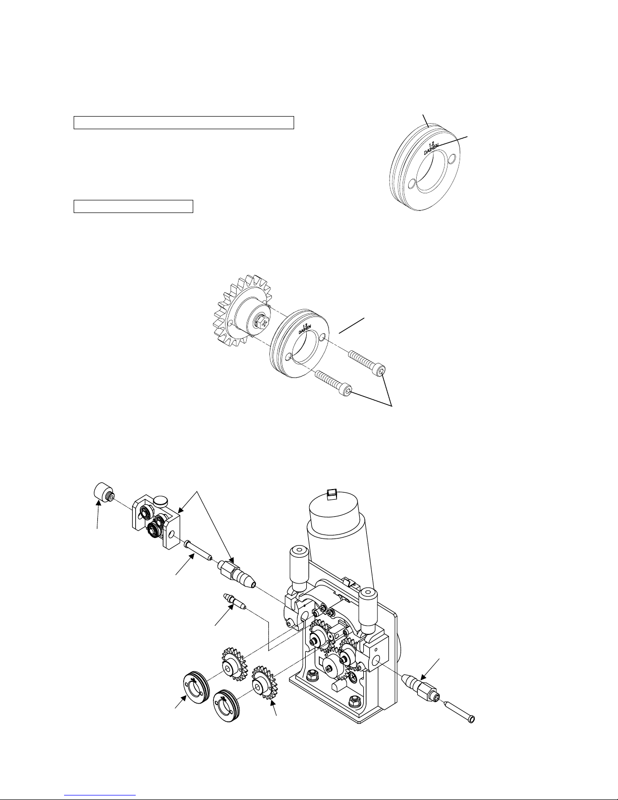
7.2 Mounting of the Feed Roll
Confirmation of the wire size marked on the feed roll
Use the right groove of the feed roll for the wire size.
The feed roll of φ0.045in [1.2mm] wire size is mounted on the
CM-741 wire feeder when shipping.
Replacement of the feed roll
1. Remove the hexagon socket cap screws fixing the feed roll.
2. Bring down the pressure handle, and then lift the pressure roll holder.
3. Separate the feed roll from the wire feeder by pulling out the feed roll.
4. Mount the new feed roll, with the wire size marked on the wire feeder facing out.
・For aluminum welding
1. Remove the pressure roll.
2. Change the center guide for aluminum.
3. Attach the middle gear and feed roll for aluminum.
4. Attach the wire straightner.
Groove for 0.045in
[1.2mm] wire size
Wire size mark
Hexagon socket cap screws
Feed roll
Pilot
Wire straightener
Inlet guide
Center guide
Guide adapter
Feed roll
(Pressure roll) Middle gear
No. U5278
―15―
7. WELDING PREPERATION (continued)
Adjusting of the wire pressure and straightener
•
Set to the proper wire pressure for the wire type by turning the pressure handle.
•
The numeral on the pressure scale set with the right pressure handle should be correspond to the
one set with the left pressure handle.
Recommended wire pressure adjustment
Wire diameter Wire pressure scale
Solid wire Flux cored wire
φ1/16in [1.6mm], φ5/64in [2.0mm] 4 - 5 3 - 4
φ0.045in [1.2mm], φ0.052in [1.4mm] 3 - 4 2 - 3
φ0.035in [0.9mm], [φ1.0mm] 2 - 3
φ0.030in [0.8mm] 1 - 2
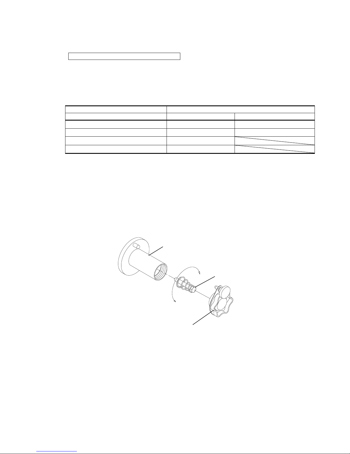
7.3 Adjusting of the wire reel hub
After performing inching operation, take care to adjust the brake of the wire reel hub to prevent the
wire from going too slack. The brake has been properly adjusted before shipment. Therefore,
readjustment of the brake is not required for welding in standard welding conditions.
How to adjust the wire reel hub
1. Detach the cap knob from the wire reel shaft.
2. Adjustment of the brake can be achieved by turning the hexagon bolt (M10).
Wire reel shaft
Hexagon bolt (M10)
Cap knob
To brake more quickly,
turn the bolt clockwise.
To brake more slowly, turn
the bolt counter-clockwise.
No. U5278
―16―
7. WELDING PREPERATION (continued)
7.4 Feeding Wire by Inching Operation
WARNING
● Do not look into the tip hole to check for the rate of wire feeding while inching.
CAUTION
● Keep away your hands, fingers, hair or clothes from the rotating parts of the feed
roll, etc. to prevent you from being caught into the rotating parts while inching.
After straightening the welding torch, feed the wire by
pressing the INCHING key. (the INCHING lamp located at
the upper right of the INCHING key lights up). When the
wire appears from the end of the torch, press the INCHING
key again (the INCHING lamp goes out). Cut the wire at
about 0.4in [10mm] from the end of the tip. Wire feed
speed can be adjusted by turning the parameter adjusting
knob.
WARNING
Touching the charging parts may cause fatal electric shocks and burns.
● Never touch the charging parts in the wire and wire feeder.
The parts indicated as in the figure below are the charging parts during
welding.
インチング
INCHING key
Parameter adjusting knob
Wire
No. U5278
―17―
7. WELDING PREPERATION (continued)
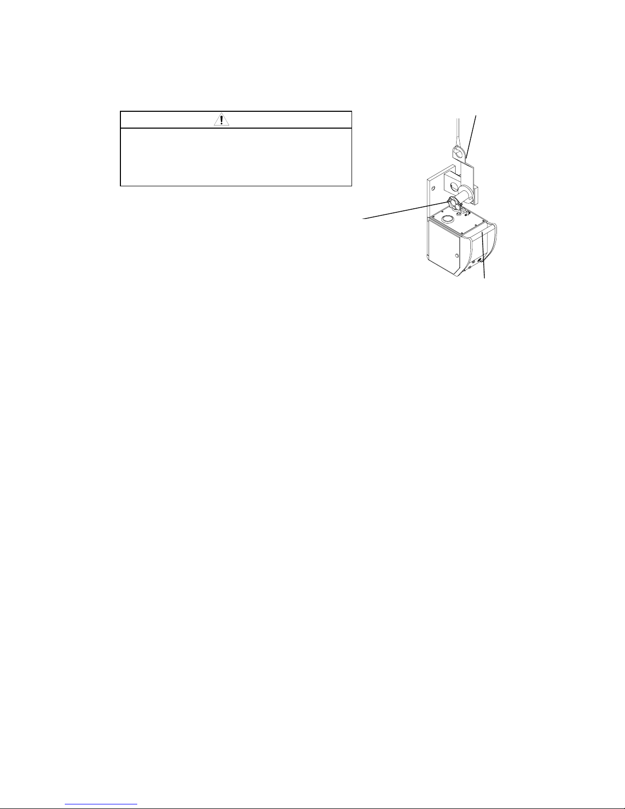
7.5 Hanging the Wire Feeder
CAUTION
● When hanging the wire feeder, firmly fix the
cap knob and clamp screw to prevent the
device from dropping.
● Do not use the carrying handle of the wire
feeder to hang the wire feeder.
Screw to clamp the cap knob
Hanging bracket (optional)
Carrying handle

No. U5278
―18―
8. MAINTENANCE AND TROUBLESHOOTING
8.1 Carrying Out Maintenance
WARNING
● Do not touch the charging parts inside or outside of the wire feeder.
● Disconnect the welding power source by turning off the line disconnect switch in
the power box to avoid an electric shock before carrying the equipment.
No. Problem Cause Solution
1 Wire gets deformed. Wire pressure is too strong. Refer to “Recommended wire
adjustment” in Section 7.2.
Feed roll of wrong wire size is
used.
Replace it with the feed roll of
proper wire size.
Feed roll and pressure roll are
worn.
Replace the feed roll and the
pressure roll with a new ones.
2 Wire is not fed. Poor contact or breakdown in
the control cable.
Poor contact or breakdown in
the encoder cable
Check the socket. Check the
cables and replace with new ones if
necessary.
Poor contact or breakdown in
the voltage detection cable
Trouble with the motor Replace the motor with a new one.
Wire pressure is too weak. Refer to “Recommended wire
adjustment” in Section 7.2.
Dust and chip are accumulated
on the outlet guide and on the
feed roll.
Remove the dust and chip.
3 Pressure roll does not
rotate smoothly.
Failure of the pressure roll
holder.
Replace it with a new one.
4 Shield gas is not
supplied when
pressing the torch
switch.
The discharge valve of the gas
cylinder is closed.
Open the valve.
Lack of gas pressure in the gas
cylinder
Check gas pressure.
Failure of gas solenoid valve After checking the gas solenoid
valve, replace it with new one.
5 Shield gas supply does
not stop.
Failure of gas solenoid valve Check the socket. Check the
cables and replace with new one.
6 Defective gas hoses Crack in the gas hose Replace them with new one.
7 Wire is not fed
smoothly through the
wire reel.
Adjustment of the brake is either
too strong or too weak.
Refer to “Adjustment of the wire
reel hub” in Section 7.3.
Table of contents
Other OTC DAIHEN EUROPE Welding System manuals


Popular Welding System manuals by other brands

TOP GUN WELDING
TOP GUN WELDING TGWTIG195DCPULSE user manual

Summit Racing Equipment
Summit Racing Equipment PC40 owner's manual

ENEL
ENEL 200TH user manual

Mosa
Mosa TS 350 YSX BC Use and maintenance manual

LORCH
LORCH EC-Clean 1000R Operation manual

EWM
EWM Tetrix 200 MV Comfort puls 5P TG operating instructions


Lincoln Electric
Lincoln Electric OPTIMARC CV500P Operator's manual

Lincoln Electric
Lincoln Electric INVERTEC V350-PRO IM708 Operator's manual

Telwin
Telwin INFINITY TIG 225 instruction manual

Lincoln Electric
Lincoln Electric 11476 Operator's manual

FIBER FOX
FIBER FOX Mini 4S user manual

CEA
CEA MATRIX 420 E Operator's manual