OTC Wireless WiSER2400 User manual

802.11b Wireless Serial Port Adapter
WiSER2400 User Guide
Version 1.06

WiSER2400
Wireless Serial Port Adapter
User Guide
Copyright
Information in this document is subject to change without notice. Complying with
all applicable copyright laws is the responsibility of the user. No part of this
document may be reproduced or transmitted in any form or by any means,
electronic or mechanical, for any purpose, without the express written permission
of the seller. If, however, your only means of access is electronic, permission to
print one copy is hereby granted.
The seller provides this documentation without warranty, term, or condition of any
kind. The seller may make improvements or changes in the product(s) and/or the
program(s) described in this documentation at any time.
Other product and company names herein may be trademarks of their respective
owners.
Copyright 2001 OTC Wireless, Inc. All rights reserved.
Revision 1.06 01/03/03
ii

Table of Contents
WiSER2400 Use Guide
Chapter 1 Introduction 1
Data Sheet 3
Chapter 2 Installation of WiSER2400 4
Installation of WiSER2400 Hardware 4
Installation of WiSER2400 Software 6
Chapter 3 Diagnostic and Configuration Utility 7
Overview 7
Connection and Overall Status Panel 8
Radio Status Panel 8
Configuration Panel 9
RS232 and WLAN Statistics Panel 10
Security Panel 11
Chapter 4 Troubleshooting 14
Blank Pages Appear When Open the Utility Program 14
No Radio Link 14
No Data Transfer While the Radio Link is Good 14
Poor Link Quality 15
Radio Interference 15
Technical Support 16
Appendix A: Limited Warranty 17
WiSER2400 Hardware 17
WiSER2400 Software 17
Appendix B: Regulatory Compliance 18
FCC Part 15 Declaration of Conformity (DoC) 18
FCC Rules and Regulations - Part 15 18
FCC Radiation Exposure Statement 18
European Community (EC) Directives Conformity 19
and Restrictions
Glossary 20
iii

Chapter 1
INTRODUCTION
WiSER2400 is an 802.11b compliant, or WiFi, radio with a RS232 serial
interface.
The radio takes serial data from the equipment or computing device connected to
it via its RS232 port, converts the serial data into 802.11-compliant data packets,
and transmits these packets with the RF modulation that is compliant with the
specifications of the 802.11b physical layer. On the receiving end, the radio
demodulates the RF signal, removes the Ethernet (802.11) headers, unpacks the
packet and delivers the data byte-by-byte to the destination equipment/device
through the RS232 serial port.
The radio can be configured either as a “Station” or as an “Access Point” in
accordance to the 802.11 standards. It can operate either in the ad hoc or the
infrastructure mode defined by the 802.11 standards. As such, this radios
enables RS232-interfaced devices to participate in an Ethernet network. In this
capacity, the radio, in addition to eliminating the RS232 cables, functions as a
media converter for RS232-interfaced equipment and computing-devices.
Due to the fact that most existing RS232 applications involve RS232 interfaces
on both ends of a communication link, standard WiSER2400 radios are currently
shipped in pairs. However, a single WiSER2400 radio is perfectly capable of
connecting RS232-interfaced equipment wirelessly to another non-RS232-
interfaced 802.11b radio as long as software exists on the other end to properly
receive the data in Ethernet packets. For such single-radio applications, please
contact OTC for more information.
The radio is fully self-contained in performing the conversion between serial data
and wireless-Ethernet packets. That is, no device driver needs to be installed on
the hosting equipment or computing device the radio is connected to. True Plug
& Play feature therefore is achieved with any equipment or computing devices
with a RS232 port. This also means the radio can be used on equipment and /or
computing-devices with any Operating Systems. This is particularly useful for
instruments/equipment where the use of RS232 interface is widespread.
Examples include cash registers, electronic whiteboards and navigation
instruments.
WiSER2400 has a compact form-factor that blends easily into an office/
classroom environment. It also lends particularly well to portable applications.
The specifications are given on the next page.
1
The Utility program can be used to monitor the communication condition once the
radio is in operation. The radio runs self-sufficiently without the aid of any driver
program in the host equipment or computer connected to the radio. This Utility
program therefore is intended to be, in most cases, just a tool for the network

operators. An end user simply plugs the pre-configured radio into a host
equipment or computer equipped with a RS232 receptacle without ever being
expose to this Utility program. The Utility program is simple to install and easy to
use through its graphic user interface. The details are described in Chapter 3.
2

WiSER2400 WiFi Radio
Specifications
Model WiSER2400
Standard 802.11 and 802.11b
Host Interface RS232
Frequency 2.4GHz – 2.495GHz
RF Channels 11 channels (US, Canada), 13 channels (Europe), 14 channels
(Japan)
Transmission power 14dBm at antenna input typical
Receiver sensitivity -80dBm @1e-5 BER typical
Antenna Integrated dipole antenna with ~2dBi gain
Data Rate 11, 5.5, 2 or 1 Mbps fixed rate, or configured to automatic rate
selection
Modulation CCK, Direct Sequence Spread Spectrum
Link Distance ~1200 ft in open space
Network Types Support dedicated point-to-point link, the ad hoc mode and the
infrastructure mode
Data Encryption Support the standard 64-bit and the 128-bit WEP
Network Security MAC-address-based access control
AC adapter Output: 5V, 1A; Input: 100-120V, 50-60Hz, ~0.3A
Current consumption <480mA (max. reached in transmit-mode)
LED Indicators 4: Power, Transmission, Receiving, Link
Operating
Temperature
-10°C – 50°C
Regulation
Compliance
FCC part 15,Class B
CE ( ETSI EN 300 328-1, ETSI EN 301 489-17)
3
Key Features
Configurable as either an Access Point or a Station
Configurable as a dedicated pair of radios to replace a RS232 cable connection
Plug & Play operation—
o No driver on the host device is required for radio operation
o Radio operation is independent of the operating system on the host equipment or device
(Windows 98/2000/ME, Linux, Unix, embedded, etc.), as long as a RS232 port is properly
supported
Automatic clear channel selection when configured to operate as a dedicated radio pair
Supports 64-bit and 128-bit encryption for secured communication
Industry standard IEEE 802.11b-compliant wireless interface; Interoperable with AP and Client
radios from other vendors)
Enable a RS232-interfaced equipment to participate in an Ethernet network via an 802.11b-
compliant Access Point
11Mb
p
s data rate and automatic selection of lower data rate
(
5.5
,
2 and 1 Mb
p
s
)
in de
g
raded RF
Applications
Standard-compliant wireless networking for computers and equipment with a RS232 interface
Embedded devices, tools, instruments, equipment and appliances that can benefit from the re-
configurability of wireless link yet are unfriendly to the installation of device-drivers
o
o Control/monitor equipment where mobility is required
POS equipment for stores where re-configuration is frequent

Chapter 2
INSTALLATION OF WiSER2400
Installation of WiSER2400 Hardware
Standard Hardware Items
2 WiSER2400 radios
1 2-foot RS232 cable
1 3-foot RS232 cable (option –S, or –N, or –P)
1 ac-dc adapter
1 USB power adapter
1 pair of Velcro mounting pads
Power
This radio connected to your equipment draws power from an AC adapter that
plugs into a wall outlet. The radio connected to your computer draws the power
from a USB power adapter cable that plugs into the USB port of a notebook or
desktop computer.
Power can also be injected from the WiSER2400 over the RS232 cable (Option –
S and -N) to the equipment connected to the radio.
RS232 Connection
A pair of WiSER2400 radios is shipped with two RS232 cable. One of the cables
is 2 feet long and always has a female DB-9 connector at one end. This 2-foot
RS232 cable is used to connect a computer in a standard configuration. The 3-
foot cable is intended for use with any RS232 equipment (whiteboard,
instrument, etc.) and comes in one of the options listed below:
Option –S—terminates in a female DB-9 connector, when connected to a
powered-on radio, pin 1 supplies 5V, up to 350mA DC power
Option –N—terminates in a male DB-9 connector, when connected to a
powered-on radio, pin 7 supplies 5V, up to 350mA DC power
Option –P—terminates in a male DB-9 connector, no dc-power is available
from this cable
Connect the modular plug (which resembles an over-sized telephone plug) of the
RS232 cable to the modular jack (which resembles an over-sized telephone jack)
at the bottom panel of the WiSER2400 radio. Connect the DB-9 (9-pin, can be
female or male depending on the equipment) connector of the RS232 cable to
the RS232 port in the client equipment or computer.
Standard WiSER2400 radios operate at a data rate of 9600 baud. WiSER2400-M
operates at data rate of 19,200 baud. The WiSER2400 radio, however, is
inherently capable of supporting data rate up to 115K baud. Contact OTC for
applications that require customized or utility-configurable data rate.
4

Status LED’s
Power on the WiSER2400 Radio, the LED’s on the front panel should exhibit the
following patterns:
LED Color Light Blinking
Pattern
Indication
ON RED Steady on Proper power is supplied
Steady on Unit linked to another unit or Unit is
configured as an AP
RX GREEN
Steady blink Unit not linked to any unit
TX RED Flickering Unit transmitting RF signal
LINK YELLOW Steady on Not in use
When the radio is configured as a Station, one of the most useful diagnostic tools
may be the green RX LED: a blinking green RX LED indicates the absence of a
useful communication link. If you are using a pair of the radios in a dedicated
point-to-point link, good radio communication is expected only if the green RX
LED’s on both radios are steadily on.
Once the hardware is checked out to work properly with the intended host device
or equipment, the radio can be secured in the desire location by the pair of
Velcro pads supplied.
5
USB power
2-foot RS232
3-foot “-S”
RS232 cable
Radio Power
An installation example where the
p
ower for the RS232 equipment
(whiteboard) is supplied by the
radio over the RS232 cable
3-foot “-P”
RS232
Whiteboard
Powe
r
Radio Power
An installation example where separate power
supplies are used for the RS232 equipment
(whiteboard) and the radio

Installation of WiSER2400 Software
System Requirements
To use the WiSER2400 Wireless Ethernet Adapter’s utilities software, your
computer must meet the following minimum requirements:
Windows® 95 (OSR2)/ 98 (SEC)/ME/2000/XP
One COM port (with a DB-9 male connector or an appropriate adapter to connect
to a DB-9 female connector)
Installation
To install the utility program, simply insert the CD-ROM provided copy the
“WiSERUti.exe” file to the desired location on your PC.
Notice that the operation of the WiSER2400 radio is independent of the Utility
Program. Therefore, it is NOT necessary to install the Utility on the RS232
equipment/computer that connects to a WiSER2400 radio. For example, if you
connect an electronic whiteboard wirelessly to a network using a pair of
WiSER2400 radios, you need not to install Utility Program on the whiteboard and
you will not be able to! You can configure the WiSER2400 radio on a PC installed
with the Utility Program, disconnect it from the PC, and then connect it to the
whiteboard. While the Utility program must run on a computer equipped with
Microsoft Windows, the radio can operate with computers/equipment of any OS.
6
Also, notice that to configure or monitor the radio with the Utility program,
the computer cannot be running another program that also access the
same COM port.
Chapter 3
Diagnostic and Configuration Utility
Overview
This chapter describes the functionalities and operations of WiSER2400
Diagnostic and Configuration Utility program. The utility program can be used to
configure, monitor, WiSER2400 radios. The WiSER2400 utility program is
supported on Microsoft Windows® 95(OSR2), 98(SEC), Millennium, 2000, and
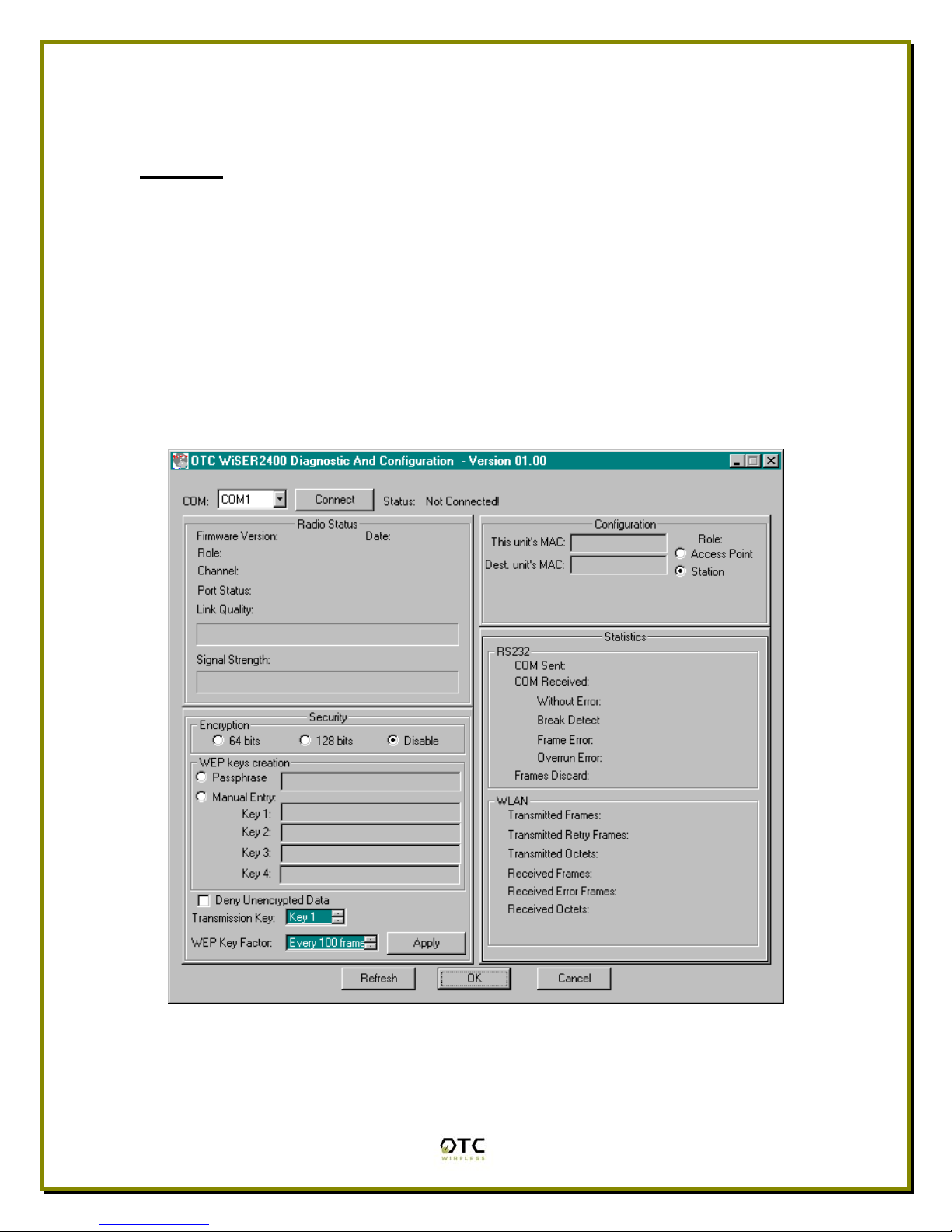
XP. Figure 1 below is WiSER2400 utility main window.
Warning: The utility program may not work simultaneously with another RS232
application program since both programs compete for the access to the same
COM port (RS232 serial port) connecting the WiSER2400 radio.
Figure 1. Main Window of WiSER2400 Utility Program
In general, the main window consists of five panels: Connection and Overall
Status, Radio Status, Configuration, Security, and RS232 and WLAN Statistics.
7

Connection and Overall Status Panel
The Connection and Overall Status panel, shown in figure 2, controls and
maintains the serial connection, and displays up-to-date connection status. It
has a pull down menu for choosing COM ports, a Connect button, and a text
field displaying connection status.
Figure 2. Connection and Overall Status Panel
The pull-down menu allows users to select COM ports (RS232 serial port) so that
the utility program knows where to connect to WiSER2400 radio unit. The pull-
down menu becomes inactive and inaccessible when the connection between
the WiSER2400 radio and the utility program is active.
After appropriate COM port is selected from the pull-down menu, click Connect
button to have the utility program claim the COM port. If a COM port is
successfully claimed by the utility, the Disconnect will be displayed on the
button instead of Connect. Click Disconnect button to release the control of the
COM port from the utility program.
Warning: When the COM port is claimed by the Utility program, it is not
guaranteed that the link between the WiSER2400 radio and the utility program is
established. The utility program simply takes control of a specific COM port which
can be connected to any device.
Note: Other panels in the main window stay inactive unless a COM port is
claimed by the utility program.
The status text field displays connection status and all command information
moving back and forth between WiSER2400 utility program and the radio unit.
Radio Status Panel
The Radio Status Panel has two modes, STA mode and AP mode, shown in
figure 3.
8

Figure 3. Radio Status Panels (AP: left; Station: right)
The modes switch automatically depending on the role of the WiSER2400 radio
unit connected to the COM port. When the radio unit acts as an AP, the radio
status panel is shown in AP mode. Likewise, when the radio unit acts as a
station, the radio statue panel is shown in STA mode. To retrieve or update the
Radio Status Panel, click Refresh button at the button of the main window.
In general, the Radio Status Panel of both modes displays the firmware version,
firmware release date, role, and communication channel used by the radios. In
AP mode, the panel displays additional information such as Beacon interval. In
station mode, the panel displays additional radio signal information such as the
Port Status, Link Quality, and Signal strength.
Configuration Panel
The Configuration panel is used to display MAC addresses, role of the radio
unit, the radio channel in use. The Configuration panel has AP mode and station
mode shown in Figure 4.
Figure 4. Configuration Panel
NOTE: The firmware is embedded with the “Auto Channel Scan” feature. This
means the Access Point automatically detects in-use channels and selects the
one that is not in-use. Therefore, users cannot manually change the channel
number.
To retrieve the configuration setting of the connected WiSER2400 radio unit, click
Refresh button located at the bottom of on the utility main window. If the settings
are retrieved successfully, the information such as MAC addresses and the
9

channel in use is automatically displayed in the appropriate fields in the
Configuration panel.
RS232 and WLAN Statistics Panel
The transmission statistics of the RS232 (COM port) and Wireless Local Area
Network (WLAN) is shown in this panel. To retrieve the statistics, click Refresh
button located at the bottom of the main window of the utility program. The
following explains the statistics shown in the panel:
1. RS232 Statistics:
a. COM Sent: This number is the total bytes that the Unit sends
through the connected COM port.
b. COM Received: This number is the total bytes that the Unit
received through connected COM port. This value is the sum of the
following values:
i. Without error: Total bytes received without error.
ii. Break Detect error: Total bytes received as break detect
error.
iii. Frames error: Total bytes received with frame error.
iv. Overrun error: Total bytes received with overrun error.
c. Frames Discard: This number is the total number of frames that
were discarded while the firmware tried to en-queue them to WLAN
queue (send to MAC). Lacking of memory is the main reason for a
frame to be discarded.
2. WLAN Statistics:
a. Transmitted Frames: This number is the total UniCastFrames and
MultiCastFrames that the MAC successfully transmitted
b. Transmitted Retried Frames: This number is the total
SingleRetryFrames and MultiRetryFrames that the MAC
transmitted.
c. Transmitted Octets: This number is the total bytes that the MAC
successfully transmitted (UnicastOctets and MulticastOctets)
d. Received Frames: This number is the total UniCastFrames and
MultiCastFrames that the MAC successfully received.
e. Received Error Frames: This number is the total frames that the
MAC received with the following errors: DiscardNoBuffer,
DiscardsWrongSA, DiscardWepUndecryptable, and Frame-Check-
Sequence Errors.
f. Received Octets: This number is the total bytes that the MAC
successfully received (UnicastOctets and MulticastOctets)
10
Security Panel
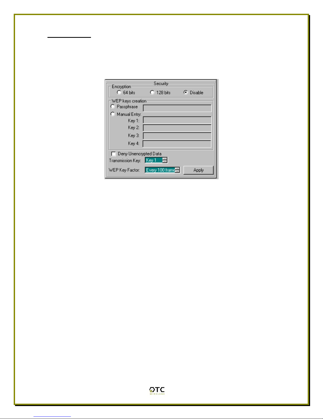
This panel shown in Figure 5 enables users to configure security options for the
WiSER2400 radios. WiSER2400 supports Wired Equivalent Privacy (WEP)
encryption both 64bits and 128bits.The Security panel contains two sub-panels,
Encryption sub-panel and WEP Keys Creation sub-panel.
Figure 5 Security Panel
Encryption sub-panel
This sub-panel allows user to adjust the security level as needed. There are
three radio buttons to select the encryption levels, and only one radio button can
be selected at a time. The function of each radio button is described below:
a. Disable: if checked, the WEP is turned off and WEP Keys Creation sub-
panel becomes inactive.
b. 64-bits: if checked, the WEP is turned on using 64-bit encryption and
WEP Keys Creation sub-panel becomes active.
c. 128-bits: if checked, the WEP is turned on using 128-bit encryption and
WEP Keys Creation sub-panel becomes active.
Before applying the WEP 64 or 128-bit encryption to the radios, the user must
complete the key settings in WEP Keys Creation sub-panel first.
WEP Keys Creation Sub-panel
This sub-panel allows user to generate users’ own WEP encryption keys and can
be made active only when either 64 bits or 128 bits radio button in the Encryption
sub-panel is selected.
There are two methods to generate WEP encryption keys. One is to use auto key
generation through the Passphrase field, and the other method is to manually
input a set of keys in the Manual Entry fields.
11

To auto-generate WEP encryption keys, select the radio button next to the
Passphrase label and then the users can enter up to any 64 characters in the
Passphrase field. Click the Apply button to apply the encryption key setting.
Notice that when this method is selected the Manual Entry fields are “grayed out”
to disallow manual entries of WEP keys.
Figure 6 Create WEP Keys with Passphrase
To manually input keys, select the radio button next to the Manual Entry and then
enter hexadecimal numbers to the fields next to Key 1 to Key 4. Click the Apply
button to apply the encryption key setting. Notice that when this method is
selected the Passphrase field is “grayed out” to disallow any input to the
passphrase field.
Figure 7 Create WEP Keys with Manual Entries
The Manual Entry Key 1/2/3/4 fields accept hexadecimal inputs as the encryption
keys. If 64 bits encryption is enabled, each key field allows the user to enter up to
12

10 hexadecimal characters. If 128 bits encryption is enabled, each of the key
field allows up to 26 hexadecimal characters.
The remaining fields in the Security Panel are described below.
a. Deny Unencrypted Data Frames: if checked, the firmware will block
unencrypted data frames from being received.
b. Transmission key: This allows user to choose from key 1 to key 4 for
transmission. The default key is set to Key 1.
c. WEP key factor: this list box allows user to choose how many frames the
Initialize Vector (IV) is reused. It contains four options: every frame, every
10 frames, every 50 frames, and every 100 frames. The default key factor
is Every 100 frames.
When the Apply button is pressed, the program validates all entered data and
prompts the user to re-enter the data if any of the input data is invalid. If all data
is valid, the entered data will be applied to the radio unit. When the Cancel
button is clicked, all entered data under Security Panel is discarded.
13

Chapter 4
Troubleshooting
Blank Pages Appear When Open the Utility Program
It is possibly due to the unavailability of the COM port. Please pay attention to the
Connection and Overall Status field next to the Connect button. Press the
Connect button again to see if the status indicates “Connected.” If not, check to
see if you have another running program that access the same COM port.
No Radio Link
If the Link Quality indicator in the Radio Status panel shows 0%, check the
following for possible causes:
• Make sure that a target radio, an AP or a Station, is turned on and
operating properly by checking LED’s on the radio.
• Make sure that the Signal Strength indicator under Radio Status panel is
not zero. A minimum of 20% is recommended. If the “Signal Strength” is
less than 20%, the distance between the WiSER2400 and the targeted
radio (an AP or another Station) may be too far. Decrease the distance
between the radio pair to see if the radio link can be established.
• If two WiSER2400 radios are meant to operate as a dedicated point-to-
point link, make sure that one radio in the pair has the role of AP and the
other has the role of Station. No link can be established if both radios are
set up as the same role.
• Make sure that the encryption keys are entered correctly if WEP
encryption is enabled.
• Make sure that there is no RF interference present in the radio network.
No Data Transfer While the Radio Link is Good
If the Link Quality indicator shows good link quality, but the host
computer/equipment cannot properly exchange data:
• Make sure the RS232 cables are properly connected to the radios and
computer/equipment.
• Make sure that the RS232 cables in use are not defective.
14
• Make sure that the COM port on the computer/equipment is available, not
used by another active program/process.

Poor Link Quality
If the Signal Strength indicator is reasonably high (>20%) and the Link Quality is
not zero, but the “Link Quality” stays in the Poor range, it could be due to one of
the following reasons:
• Make sure that radio interference is not present in the radio network.
• Make sure that the radio is not surrounded by many strongly reflecting
(metallic) surfaces. With multiple reflecting surfaces between the radio in
question and the target radio, a severe multi-path problem may introduce
high bit error rate despite a strong Signal Strength.
• Make sure that there is no severe packet collision caused by a “hidden
node” problem. A “hidden node” problem is the situation where the RF
signal from two or more Station radios cannot reach each other (but can
reach the AP). In such situation, multiple Stations may attempt to transmit
data packet to the AP at the same time and therefore cause packet
collision. To solve this problem, re-arrange the Stations in question such
that the RF signals are mutually sensible by all Stations. There is no
guarantee that the packet collision can be entirely eliminated, but the
severity can be reduced enough to see visible improvement of the link
quality.
Radio Interference
You may be able to minimize RF interference by doing the following:
• Although WiSER2400, when properly configured, seeks a clear channel to
use, it cannot avoid interference if too many 2.4GHz interference sources
are present. A “clear” channel should be at least 20MHz, but preferably
30MHz, apart from any other channel in use. Find out other usages in this
frequency band in the vicinity and try to coordinate the channel
assignment with other users.
• Reseat the WiSER2400 radio to a location where the interference is
minimized; in general, increasing the distance between the radio pair may
cause radio interference.
• Avoid using 2.4GHz cordless phone in the vicinity of the radios
• Keep the computer with the WiSER2400 radio away from the microwave
oven and large metal objects.
• Consult the dealer or an experienced radio technician for help and
assistance.
15

Technical Support
If problems are still not solved, please contact our Technical Support to obtain
further assistance.
Call: 1-800-770-6698 in USA
Call: 011-510-490-8288 outside of USA
16
E-mail:[email protected]

Appendix A:
Limited Warranty
WiSER2400 Hardware
The seller warrants to the end user (“Customer”) that this hardware product will
be free from defects in workmanship and materials, under normal use and
service, for one (1) year from the date of purchase from the seller or its
authorized reseller. The seller’s sole obligation under this express warranty shall
be, at the seller’s option and expense, to repair the defective product or part,
deliver to Customer an equivalent product or part to replace the defective item, or
if neither of the two foregoing options is reasonably available, The seller may, in
its sole discretion, refund to the Customer the purchase price paid for the
defective product.
All products that are replaced will become the property of the seller.
Replacement products may be new or reconditioned.
WiSER2400 Software
17
The seller warrants to Customer that each software program licensed from it,
except as noted below, will perform in substantial conformance to its program
specifications, for a period of one (1) year from the date of purchase from the
seller or its authorized reseller. The seller warrants the media containing
software against failure during the warranty period. No updates are provided. The
seller’s sole obligation under this express warranty shall be, at the seller’s option
and expense, to refund the purchase price paid by Customer for any defective
software product, or to replace any defective media with software which
substantially conforms to applicable seller published specifications. Customer
assumes responsibility for the selection of the appropriate application programs
and associated reference materials. The seller makes no warranty or
representation that its software products will meet Customer’s requirements or
work in combination with any hardware or software applications products
provided by third parties, that the operation of the software products will be
uninterrupted or error free, or that all defects in the software products will be
corrected. For any third party products listed in the seller software product
documentation or specifications as being compatible, the seller will make
reasonable efforts to provide compatibility, except where the non-compatibility is
caused by a defect in the third party’s product or from use of the software product
not in accordance with the seller’s published specifications or user manual.
Other manuals for WiSER2400
1
Table of contents
Other OTC Wireless Adapter manuals


Popular Adapter manuals by other brands


Clas Ohlson
Clas Ohlson XF-B9001 quick start guide

IntraServer Technology
IntraServer Technology ITIpci 5100G/GF Installation and user guide

Sharp
Sharp VR-1FPN Operation manual

AudioCodes
AudioCodes MP-20 Series Quick installation guide

StarTech.com
StarTech.com USBA-BLUETOOTH-V5-C2 quick start guide

Adaptec
Adaptec AHA-3980 user guide


