OTC Wireless AVCW-G User manual

AVCW-G
Wireless Ethernet Adapter
Technical Manual
www.otcwireless.com

ii
AVCW-G
Wireless Ethernet Adapter
Technical Manual
Copyright
Information in this document is subject to change without notice. Complying with
all applicable copyright laws is the responsibility of the user. No part of this
document may be reproduced or transmitted in any form or by any means,
electronic or mechanical, for any purpose, without the express written permission
of the seller. If, however, your only means of access is electronic, permission to
print one copy is hereby granted.
The seller provides this documentation without warranty, term, or condition of any
kind. The seller may make improvements or changes in the product(s) and/or the
program(s) described in this documentation at any time.
Other product and company names herein may be trademarks of their respective
owners.
Copyright 2001-2003 OTC Wireless, Inc. All rights reserved.
Rev 1.00 August 12, 2003

iii
Table of Contents
AVCW-G Technical Manual
Table of Contents.............................................................................................................iii
Chapter 1 Introduction.....................................................................................................1
AVCW-G Radio.............................................................................................................. 2
Specifications.................................................................................................................. 2
Chapter 2: Hardware Installation...................................................................................3
Safety Statements............................................................................................................ 3
Power .............................................................................................................................. 3
Ethernet connection......................................................................................................... 4
Status LEDs..................................................................................................................... 4
System Requirements for Web-based Utility program................................................... 5
Chapter 3 Web-Based Utility Software...........................................................................6
Use the Web-Based Utility Program............................................................................... 6
Overview of the Web Pages............................................................................................ 6
Basic Information............................................................................................................ 7
Wireless........................................................................................................................... 9
Security......................................................................................................................... 10
Advance ........................................................................................................................ 12
Admin............................................................................................................................ 14
Help ............................................................................................................................... 17
Chapter 4 Troubleshooting ............................................................................................18
No Page Displayed When Accessing the Web-based Utility....................................... 18
No Radio Link............................................................................................................... 18
No Network Connection While the Radio Link is Good.............................................. 18
Poor Link Quality.......................................................................................................... 19
Radio Interference......................................................................................................... 19
TFTP Timeouts ............................................................................................................. 20
Settings Appear not to be Modified .............................................................................. 20
Technical Support......................................................................................................... 20
Appendix A: Limited Warranty....................................................................................21
Appendix B: Regulatory Compliance ..........................................................................22

1
Chapter 1 Introduction
AVCW-G is an IEEE-802.11g compliant wireless Access Point (AP) that offers a
no-frill, seamless way of fitting a wireless network into an existing wired LAN
infrastructure. It does not even require the assignment of an extra IP address.
Existing wired-network resources such as DHCP, VPN, firewall, etc., reach
across the AVCW-G to the client workstations with total transparency. Unlike
many other 802.11g compliant APs on the market, which offer network functions
that are duplicative to the existing network, AVCW-G simply wirelessly collects a
group of workstations or other kinds of computing devices into the existing
network—just like a hub or a switch.
The portable, compact form-factor of AVCW-G, in conjunction with its no-frill AP
functionality, makes it ideal for quick deployment of wireless network at events
that involves non-permanent setup: temporary offices, trade-shows, meetings,
temporary POS, etc. There is no need to request an IP address for the AP ahead
of the time. There is no worry about functionality conflicts with the incumbent
network setup when traveling to a temporary event.
Its functions do not stop there however. With link distances of up to several
miles, the AVCW-G can also be used to interconnect networks and provide
access to the Internet.
A built-in Web-based Utility program is provided for the users to pre-configure
AVCW-G prior to putting theradio in operation. And the Utility program can be
used to monitor the communication condition once the radio is in operation. Once
configured, the radio runs self-sufficiently without the aid of any driver program in
the device connected to the radio. This Web-based Utility program therefore is
intended to be, in most cases, just a tool for the network operators. The network
operator can perform remote network management of a fixed AP installation
using this Utility if a valid IP address is assigned to AVCW-G. In most cases, a
pre-configured AVCW-G AP can be plugged into a RJ-45 receptacle on the wall
of any network environment without running the Utility program. The Web-based
Utility is described in more details in Chapter 3.

2
AVCW-G Radio
Specifications
Model AVCW-G
Standard IEEE 802.11g
Host Interface Ethernet, 802.3, RJ-45 receptacle
Frequency US: 2.4GHz –2.462GHz
EU: 2.4GHz –2.472GHz
RF Channels 11 channels (US, Canada, Brazil, Australia, New Zealand)
13 channels (Europe, except France)
4 channels (France, Mexico)
Transmission power 14 dBm at antenna input typical
Receiver sensitivity -80dBm @1e-5 BER typical
Antenna Patch antenna with ~9dBi
Data Rate 1/ 2/ 5.5/ 11/ 12/ 18/ 24/ 36/ 48/ 54 Mbps
Modulation OFDM with BPSK, QPSK, 16QAM, 64QAM (11g)
DBPSK, DQPSK, CCK (11b)
Link Distance ~1200 ft in open space
Network Types Support both the ad hoc mode and the infrastructure mode
Data Encryption Support the standard 64-bit WEP and the optional 128-bit WEP
DC Supply Output: 9V, 2.6A; Input:100-120V, 50-60Hz, ~1.0A max
Current consumption <480mA (max. reached in transmit-mode)
LED Indicators 4: Power, Transmission, Receiving, Link/Ethernet-connection
Operating Temperature 0°C –50°C
Regulatory Compliance Pending
Key Features
qPlug & Play—
oNo driver on the host device is required for radio operation
oRadio operation is independent of the operating system on computer or any connecting device
(Windows 98/2000/ME/XP, MAC, Linux, Unix, embedded, etc.), as long as the device has a
properly supported Ethernet port.
qIndustry standard IEEE 802.11g-compliant wireless interface; Interoperable with AP and Client
radios from other vendors
qThe IP Bridging Mode, when enabled, allows the sharing of the Station Radio by multiple computers
qEthernet (802.3 compliant) host interface to enable true Plug & Play
qMaximum 54 Mbps data rate and automatic selection of lower data rates in degraded RF
environment
qIntegrated omni-directional-antenna to provide best tradeoff between link-quality and mobility
qRemote network management achievable through Web browser-based configuration tool run from
any OS platforms
qRemote firmware/software upgrade can be achievable from any OS platforms
qIntegrated 9 or 15 dBi antennas, or external antenna connectors for last mile wireless LAN
q

3
Chapter 2: Hardware Installation
Safety Statements
Use only the power supply adaptor provided with this product or the
manufacturer's authorized replacement power supply. Connect the power cord to
a properly grounded electrical outlet that is near the product and easily
accessible.
Refer service or repairs, other than those described in the user
documentation, to a professional service person.
DANGER: Do not set up this product or make electrical connections during
a lightning storm
NOTE: AVCW-G requires Wireless Internet Service Providers or system
integrators to provide a professional installation at the customer site; Such
installations generally include: 1) antenna installation and alignment, 2) system
installation using OTC wireless’s proprietary utility program, and 3) knowledge of
computer networking.
Power
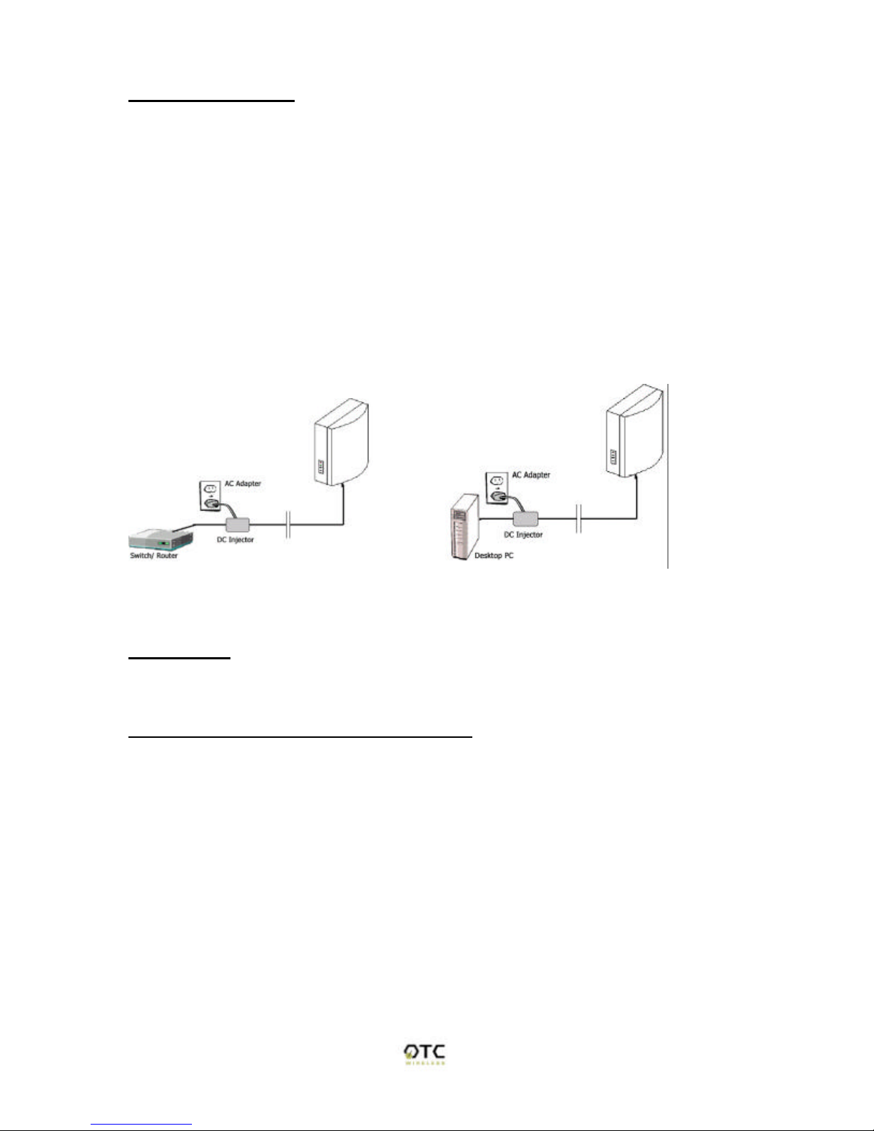
This radio uses OTC's Power-Over-Ethernet system to bring power and data to
the radio over OTC's specialized Ariel Category-5 Ethernet cable (supplied with
the standard purchase). This is accomplished by using a DC Injector that sits
between the Network and the Radio and uses a standard wall outlet for DC
power.
To setup the AVCW-G, follow the instructions below:
1. Connect the bundled 9V AC Adapter to the DC input on the bottom of the DC
Injector unit.
2. Connect the Ariel Category-5 cable that extends from the radio to the port on
the DC Injector labeled, "Radio".
3.Connect a crossover Category-5 Ethernet cable from a hub, switch or router to
the port on the DC Injector labeled "Network". If you are connecting an access
point directly to a PC, use a straight-through Category-5 Ethernet cable.
Important: After the radio units are properly installed and positioned, use the
provided coax-seal tapes to wind around and seal the connection between the
radio and Ethernet cable and, for AVCW-G, the connection between the radio
and the antenna. This prevents moisture from entering and damaging the radio.
4
Ethernet connection
Observe the yellow LED to check the status of the Ethernet connection:
If the yellow LED stays on continuously, then the Ethernet connection to the host
computer or device is not made. Check your UTP cable and cable type, and
replace if necessary. If the yellow LED is flickering, and power is on to the
device, then the Ethernet connection between the host computer and the
Wireless Ethernet Adapter is correct. If one cannot communicate, and the yellow
LED is off, you may want to re-position the AVCW-G to a different location for
better RF reception. You may also want to check if the unit is configured with the
proper RF channel and security settings by using the Utility software.
Once the hardware is checked out to work properly with the intended host device
or network equipment, the radio can be secured to a desired location using the
bundled mounting kit.
Above: (left) schematic of AVCW-G connected to a network. (right) AVCW-G connected to
a terminal PC.
Status LEDs
Use the LED status indicators to make sure that the AVCW-G station is
communicating properly:
LED Color Light Blinking Pattern
ON Green Steady on
RX GREEN Steady on
TX GREEN On, when transmitting RF signal
LINK GREEN Flickering when communicating over the Ethernet
port; steady-on when Ethernet connection is absent

5
System Requirements for Web-based Utility program
A Web-based Configuration Utility is a built-in program of the Wireless Adapter
for changing the configuration settings of the Adapter. For using the AVCW-G
Web-based Configuration Utility, your computer must meet the following
requirements:
(1) A Web browser must be installed on the computer. The supported Web
browsers include Internet Explorer 5.0 and above, Netscape 6.0 and above, and
Mozilla 1.0 and above. JavaScript for the browser must be enabled.
(2) Ethernet capable computer with RJ-45 port (either built-in or add-on NIC).
(3) A TFTP (Trivial File Transfer Protocol) client must be installed on the
computer. This requirement is only for the purpose of upgrading the software or
firmware.
No installation of any program is needed. See Chapter 3 for detailed information
of configuring the Wireless Adapter. In order to configure it, you need to know the
factory default settings.
The factory default settings are:
IP address: 192.168.1.241
Subnet mask: 255.255.255.0
(Optional) Gateway: 192.168.1.1
User name: No User Name
Password: No password

6
Chapter 3 Web-Based Utility Software
Use the Web-Based Utility Program
Once the AVCW-G is properly powered up and connected to a computer running
a Web browser on the same IP subnet, the Web-based Utility is ready for use. To
access the web utility, open a Web browser and enter http:// followed by the
current IP address of the AVCW-G in the location field, for instance
http://192.168.1.241.
For configuring your computer to match the IP subnet of your PC to that of the
AVCW-G radio, different steps must be taken on different operating systems.
Typically, a static IP address must be manually assigned to a computer and the
user must have administrative privilege to perform such operation. Here are
sample configuration steps involved on Windows and Macintosh.
On Windows, select “Start->Settings->Control Panel” and double click “Network
and Dial-up Connections” icon. In the popped up window, right-click “Local Area
Connection” icon and select “Properties” command. In the “Local Area
Connection Properties” dialog, choose “Internet Protocol (TCP/IP)” component in
the “Components checked are used by this connection” section and then click
“Properties” button. In the subsequently popped up “Internet Protocol (TCP/IP)
Properties” dialog, turn on “Use the following IP address” radio button, and enter
the IP address, subnet mask as well other information in the related fields for
your computer.
On Macintosh, select “Apple->System Preferences…” and double click the
“Network“ icon. In the popped up “Network” dialog, choose “Built-in Ethernet”
option for “Shows” dropdown menu and select the “TCP/IP” tab. Choose
“Manually” for the “Configure” dropdown menu, and then enter your IP address,
subnet mask as well as other information in the related fields for your computer.
Overview of the Web Pages
With most browsers, there are six web pages accessible through six tab links.
These web pages are hosted by a built-in web server in the AVCW-G radio.
Details of each Web page will be discussed in the following sections. The web
pages may look different; however, functions are the same depending on the
combination of operating systems and the web browser being used.
To access any hosted page, you are prompted for a user name and a password.
When accessing a hosted page for the first time, use the factory default settings
listed on the previous page.
The “Save” and “Cancel” buttons are common on “Wireless”, “Advanced”,
“Security”, and “Admin” pages. Clicking the “Save” will apply the settings
according to the displayed value in that particular web page. You will be
prompted to restart the AVCW-G unit. Please note that you may have to
manually click “Refresh” or “Reload” button of the web browser in order to see
the updated web page due to the caching mechanism of the web browser.
7
Alternatively, the user can change the setting of the internet browser such that
the browser would retrieve new web pages instead of displaying the cached web
pages.
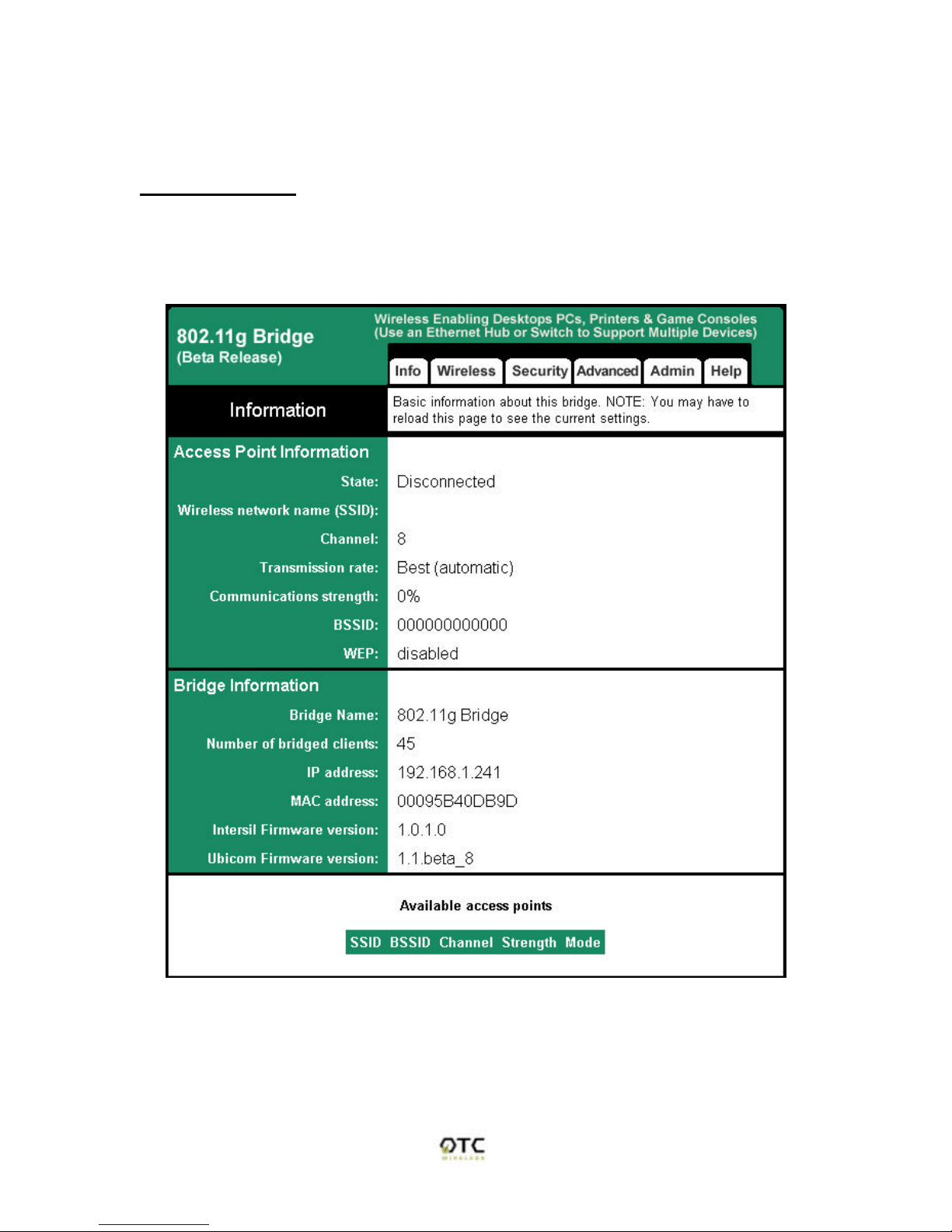
Basic Information
The “Info” page (Figure 1) is the default home page for the built-in web server.
You can click on the “Info” tab to access this page. There are three subsections
in this web page: Access Point Information, Bridge Information, and Available
Access Points.
Figure 1 “Info” Web Page (the starting page)

8
1. Access Point Information:
This section displays the information of the wireless connectivity status of AVCW-
G. Each field is described below.
State
The connection status of the wireless port
Wireless Network Name (SSID)
Shows the SSID of the AP. To change, see “Wireless Configuration” Tab
à“Wireless Network Name (SSID)”.
Channel
Shows the channel the AP is operating on. To change channel, see
“Wireless Configuration” Tabà“Channel”.
Transmission Rate
The transmission rate established with the access point if in infrastructure
mode or with a station if in ad-hoc mode.
Communication Strength
The indicator of RF communication signal strength.
BSSID
Network Identifier for basic service set
WEP
Shows if WEP (the wireless encryption standard) is enabled or not. To
enable/disable/change WEP settings, see “security” tabàWEP.
2. Bridge Information:
This section displays basic information of the AVCW-G unit
Bridge Name
Name of the AVCW-G device
Number of Bridged Clients
Number of clients connected to the AVCW-G bridge.
MAC Address
This is the MAC Address of the Access Point. It is a unique physical
address assigned to the unit by the manufacturer. MAC Address cannot
be changed.
IP Address
IP Address of the Access Point. To manually change the IP Address or let
the Access Point obtain an IP Address from a DHCP Server automatically,
see “IP Addr” tab.
9
Intersil Firmware Version
Shows the version info of the Intersil firmware.
Ubicom Firmware Version
Shows the version info of the Ubicom firmware.
3. Available Access Points
This field displays the available access points detected by the AVCW-G Bridge.
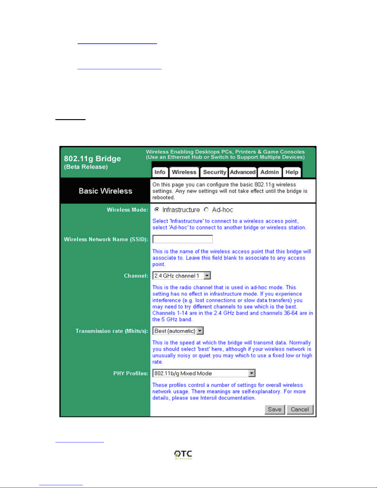
Wireless
On this page (Figure 3) you can configure the basic 802.11g access point
settings. Any new settings will not take effect until the access point is rebooted.
Figure 3. Wireless Configuration
Wireless Mode

10
Select 'Infrastructure' to connect to a wireless access point, select 'Ad-hoc' to
connect to another bridge or wireless station.
Wireless Network ID (SSID)
Acronym for Service Set Identity. This is the name used to identify which wireless
network (Access Points) the AVCW-G is going to connect with.
Channel
The channel option is only available when the AVCW-G is in ad-hoc mode. In
infrastructure mode, the AVCW-G would use the channel of the connected
access point. If you experience interference (e.g. lost connections or slow data
transfers) you may need to try different channels to see which is the best.
Channels 1-14 are in the 2.4 GHz band.
Transmission rate (Mbits/s)
This is the speed at which the access point will transmit data. Normally you
should select 'best' here. If your wireless network is unusually noisy or quiet, you
may use a fixed low or high rate. The RF environment sometimes can be hostile
to the highest data rate available. That gives rise to the need for trading off
between data rate and link robustness.
PHY Profiles
These profiles control a number of settings for overall wireless network usage.
Their meanings are self-explanatory. Users have 7 options, they are: “802.11 g
only”, “802.11 g only, Maximum Performance”, “802.11 b/g Mixed Mode”, “802.11
b/g Mixed Mode Long”, “802.11 b WiFi”, “802.11 b only”, and “Test Mode”.
Security
On this page (Figure 6) you can set the 802.11g security and encryption options.
WEP is the wireless encryption standard. To use it, you must enter the same
key(s) into the access point and the wireless stations. For 64 bit keys you must
enter 10 hex digits into each key box. For 128 bit keys you must enter 26 hex
digits into each key box. A hex digit is either a number from 0 to 9 or a letter from
A to F. Leaving a key box blank implies a key of all zeros.

11
Figure 6. Security and Encryption Settings
Enabled WEP:
This check box allows users to enable or disable WEP feature. While WEP is
disabled, all the other fields on this “Encryption” page are disabled too. A set of
four keys needs to be created in the default-key scheme.

12
Default WEP Key to Use
Select the key to be used as the default key. Data transmissions are always
encrypted using the default key. The other keys can only be used to decrypt
received data.
Deny unencrypted data:
Check this field when the WEP is enabled to deny unencrypted data. This feature
enables the adapter to drop all unencrypted packets received.
Authentication
Three options are available: ‘Open’, ‘Shared Key’, and ‘Both’. 'Open' allows
anyone to authenticate to this access point. 'Shared key' allows only stations that
know the key(s) to authenticate. 'Both' allows a station to use either mode.
WEP key length:
The 64-bit encryption is currently the 802.11 standard. The 128-bit encryption is
supported by equipment from a limited number of vendors. Note that the “user-
controlled” portion of the 64-bit encryption is just 40 bits (10 Hex digits) and that
for the 128-bit encryption is just 104 bits (26 Hex digits)—3-bytes of the
encryption key are internal to the encryption algorithm.
WEP key 1/ 2/ 3/ 4:
The keys allows hex number inputs with varying length depending on the type of
WEP being enabled i.e. 64 or128bit WEP
Advance
On this page (Figure 5) you can configure the advanced 802.11g settings such
as Bridging, advance Wireless settings, and Firmware upgrade option.
1. Bridging
To activate the Bridging mode, the user needs to select WLAN card option
allowing multiple clients connecting to an AVCW-G unit. If Ethernet client
option is selected, the AVCW-G unit can connect to only a single client.
2. Advance Wireless
Fragmentation threshold
Transmitted wireless packets larger than this size will be fragmented to
maintain performance in noisy wireless networks. In the presence of
hostile RF environment, such as interference, frames longer than this
threshold numbers in bytes are divided prior to transmission into one or
more fragments equal in length to the fragmentation threshold. The default
value is set at 2346 bytes. The maximum 802.11 data frame size, such
that no frames are ever fragmented. The valid range of fragmentation
threshold is 256 to 2346, and only even numbers are allowed.

13
Figure 5. Advanced Wireless
RTS threshold
Transmitted wireless packets larger than this size will use the RTS/CTS
protocol to (a) maintain performance in noisy wireless networks and (b)
prevent hidden nodes from degrading performance. To minimize the

14
potential packet collision associated with hidden nodes in a wireless
network, IEEE 802.11 standard has the option to complete a “Request to
Send (RTS)” and “Clear to Send (CTS)” two-frame exchange prior to
sending the real data. This reduces the throughput of the real data. Since
the probability of packet collision increases with the size of the packets
transmitted, an optimum trade-off between data-throughput and data-
integrity may be reached by turning on the two-frame exchange only for
data packets exceeding a certain size. The number entered in this field is
that threshold packet size in Bytes. For example, if “500” is entered, data
packets with sizes less than 500 bytes are transmitted without being
preceded by the RTS-CTS exchange and thereby taking a small risk of
getting corrupted by packet collisions. If “2346” (the maximum 802.11 data
frame size) or a larger number is entered, then every data packet is
transmitted without being preceded by the RTS-CTS exchange and
thereby maximizing the data throughput. The valid range of RTS threshold
is 0 to 3000.
Maximum burst time
This is also known as PRISM Nitro (tm) technology. The technology uses
fully standards-compliant methods that eliminate collisions in mixed-mode
networks, while greatly increases the performance of both pure 802.11g
and mixed 802.11b/g networks. The setting is for the amount of time the
radio will be reserved to send data without requiring an ACK. This number
is in units of microseconds. A typical value would be 1000 microseconds.
When this number is zero, bursting is disabled.
3. Firmware Upgrade
Allow Upgrade Uploads
If this box is checked, it enables the TFTP server that is used to accept
firmware upgrades. Leave this box unchecked during normal operation.
Only check the box when you are upgrading the access point firmware.
Admin
In this web page, users are able to change settings, which are used for
administration purposes. The web page is divided into four sections: Device
Name, IP settings, Security, and Commands.
1. Device Name:
Device Name
This is the name that the bridge will use to identify itself to external
configuration and IP-address-finding programs. This is not the same as
the SSID. It is okay to leave this blank if you are not using these
programs.
2. IP Settings:
IP Address Mode

15
Select 'DHCP' to get the IP settings from a DHCP server on your network.
Select 'Static' to use the IP settings specified on this page.
Default IP address
Type in the IP address of your Access Point. Allows the user to set a
static IP address to the Wireless Adapter. This IP address is only used for
accessing the built-in Web server. In order to access the Web server, the
computer must use an IP address on the same subnet of the Wireless
Adapter. It is not necessary to change this IP address to an address used
by the Wireless Network, but it is okay to do so, if desired. However, if
you do so, please consult with your system or network administrator to
obtain an IP address.
WARNING: Any changes to the following IP settings should be
contemplated carefully, documented well, and made only after
consulting your system or network administrator. Failure to do so
may result in being unable to access the built-in Web server and/or
may affect network operation.
Default subnet mask
The subnet mask specifies the network number portion of an IP address.
The factory default is 255.255.255.0. This allows the user to set the
subnet mask. If you change the IP address to one that is usable in your
network, you may need to change this setting also. Please ask your
system or network administrator for the correct subnet mask.
Default gateway
This is the IP address of the gateway that connects you to the Internet.
Allows the user to set the default gateway. If you change the IP address to
one that is usable in your network, you may need to change this setting
also. Please ask your system or network administrator for the correct
gateway.

16
Figure 7. IP Settings

17
3. Security
User Name
This is the user name that you must type when logging in to these web
pages.
Administrator Password
This is the password that you must type when logging in to these web
pages. You must enter the same password into both boxes, for
confirmation. The built-in Web server will verify the login name and
password before giving access to the hosted pages. Each time the user
name or password is changed, the Web server will prompt the user for the
new user name and password.
4. Commands
Reboot
Press this button to reboot Access Point. You will need to reboot the unit
after most of the changes you make.
Reset to factory defaults
Press this button to reset to factory default. This button allows the user to
reset all the settings to the factory defaults (not just the fields on this
Admin page!). Please be careful: once reset is completed, the current
settings are all over-written. There is no way to get back to your current
settings unless you remember them or keep an adapter settings copy. It is
always a good idea to keep a copy of the current setting before you
change the current settings.
Help
See the following figure
Table of contents
Other OTC Wireless Adapter manuals


