oti 6500 TRIO User manual

Confidential & Proprietary
Version 1.5
oti 6500 TRIO
Specification
Version 1.5
Notice
This manual contains intellectual property including
but not limited to, trade secrets and know-how,
operation procedures and production procedures that
belong solely to oti.
Disclosure, use, and/or production of any part of the
above are strictly forbidden, except under a written
license from oti.

Oti 6500 TRIO Specification Version 1.5
FCC Compliance
Confidential & Proprietary page B
FCC Compliance
The 6500 reader complies with Part 15, of the FCC rules.
Operation is subject to the following conditions:
1. This device may not cause harmful interference,
and
2. This device must accept any interference received, including interference
that may cause undesired operation.
NOTE: This equipment has been tested and found to comply with the
limits for a Class B digital device, pursuant to part 15, subpart C of the
FCC rules. These limits are designed to provide reasonable protection
against harmful interference in a residential installation. This
equipment generates uses and can radiate radio frequency energy and,
if not installed and used in accordance with the instructions, may
cause harmful interference to radio communications.
Changes or modifications in this equipment, not expressly approved by
the party responsible for compliance (On Track Innovations Ltd.) could
void the user’s authority to operate the equipment.
FCC ID: JNX-OTI-SAT6500
Responsible Party:
On Track Innovations LTD..
Z.H.R Industrial Zone.
Rosh Pina 12000
ISRAEL
Phone: +972-4-6868000
Email: info@otiglobal.com

Oti 6500 TRIO Specification Version 1.5
Table of Contents
Confidential & Proprietary page 1
Table of Contents
FCC COMPLIANCE.....................................................................................................................................B
TABLE OF CONTENTS................................................................................................................................1
TABLE OF FIGURES....................................................................................................................................2
1INTRODUCTION ..................................................................................................................................3
1.1 CERTIFIED AND SUPPORTED APPLICATIONS ......................................................................................4
1.2 SUPPORTED STANDARDS ..................................................................................................................5
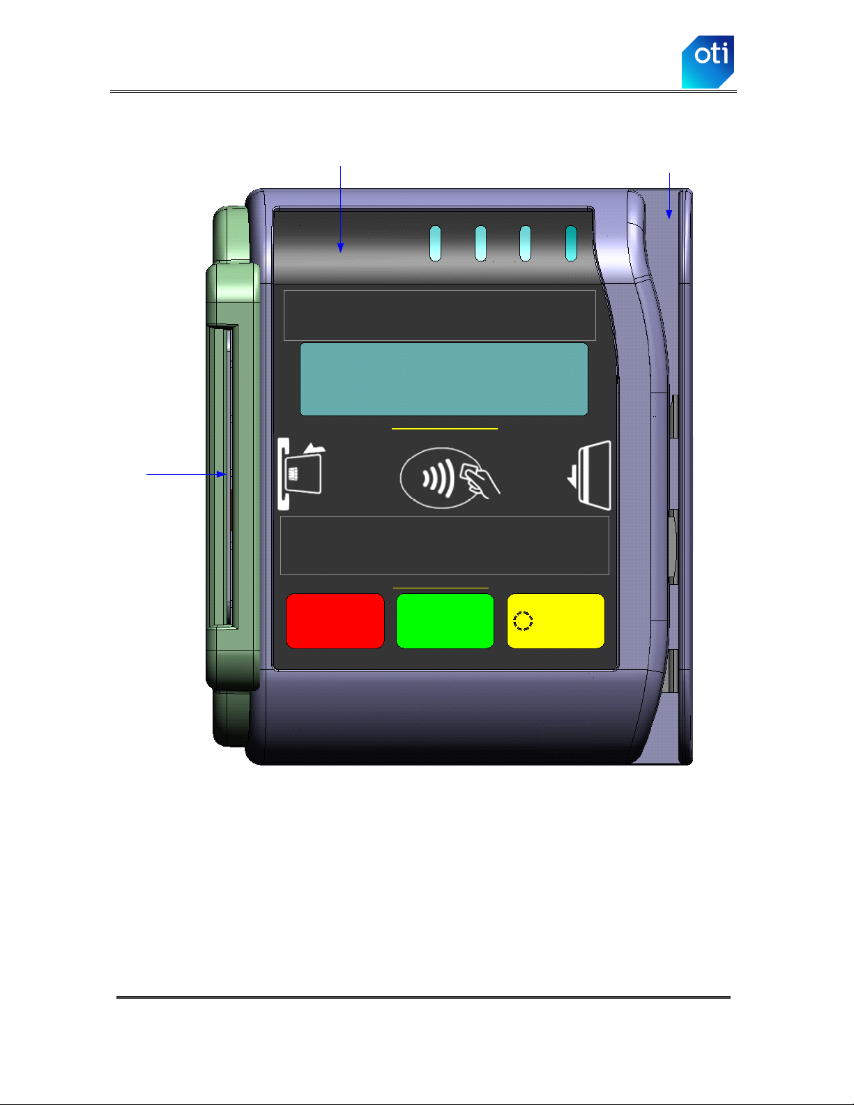
2BASIC OPERATION.............................................................................................................................6
2.1 MAGNETIC STRIPE............................................................................................................................7
2.2 CONTACTLESS ..................................................................................................................................7
2.3 CONTACT..........................................................................................................................................7
3TECHNICAL SPECIFICATIONS .....................................................................................................10
3.1 PRODUCT FEATURES.......................................................................................................................10
3.2 PRODUCT TECHNICAL SPECIFICATIONS ..........................................................................................11
4INTERFACE.........................................................................................................................................13
4.1 PIGTAIL CABLE WITH DEFAULT CONNECTOR .................................................................................13
4.2 PIGTAIL CONNECTOR CABLE WIRING.............................................................................................14
5DIMENSIONS ......................................................................................................................................15
5.1 6500 TRIO .....................................................................................................................................15
5.2 SPACER...........................................................................................................................................16
5.3 MOUNTING PLATE ..........................................................................................................................17
5.4 DRILLING TEMPLATE......................................................................................................................18
6INSTALLATION..................................................................................................................................19
6.1 ASSEMBLY IN BILL ACCEPTOR CUTOUT .........................................................................................19
6.2 SURFACE MOUNTING ON VENDING MACHINE (WITHOUT BILL ACCEPTOR CUTOUT).....................20
7CRADLE ...............................................................................................................................................21
7.1 6500 TRIO FOR ATTENDED USE.....................................................................................................21
7.2 CRADLE STRUCTURE ......................................................................................................................22
8CONTACT US......................................................................................................................................24

Oti 6500 TRIO Specification Version 1.5
Table of Figures
Confidential & Proprietary page 2
Table of Figures
Figure 2-1: 6500 TRIO –Front View ................................................................................................8
Figure 2-2: 6500 TRIO Full and Partial Configuration......................................................................9
Figure 4-1: 6500 TRIO with Pigtail Connector Cable.....................................................................13
Figure 4-2: Pigtail Connector Cable Wiring....................................................................................14
Figure 5-1: 6500 TRIO Dimensions.................................................................................................15
Figure 5-2: Spacer Dimensions........................................................................................................16
Figure 5-3: Spacer Picture................................................................................................................16
Figure 5-4: Mounting Plate Dimensions..........................................................................................17
Figure 5-5: Mounting Plate Picture..................................................................................................17
Figure 5-6: Drilling Template..........................................................................................................18
Figure 7-1: 6500 TRIO within its Cradle.........................................................................................21
Figure 7-2: Cradle parts....................................................................................................................22
Figure 7-3: Cradle Dimensions........................................................................................................23

Oti 6500 TRIO Specification Version 1.5
Introduction
Confidential & Proprietary page 3
1Introduction
The 6500 TRIO reader is a modular payment device that can support up to three cashless payment
interfaces in one small stylish enclosure. The reader is designed specifically for installation in
vending machines to allow cashless payment with magnetic payment cards, as well as proximity,
vicinity, and Contact EMV payment cards.
This device contains three reader interfaces:
Magnetic card swipe reader, which contains a vertical card swipe slot supporting Track 1 and
Track 2 data.
Contactless reader, which supports ISO/IEC 14443 A&B proximity and ISO/IEC 15693
vicinity tags and cards. The reader supports the major financial contactless programs.
Contact interface, which supports all EMV financial chip cards.
LCD, LEDs and a buzzer give the user quick transaction confirmation and clear interactive
feedback. The 6500 TRIO uses oti’s patented matched antenna technology.
The reader modular design allows customers to order the reader using a wide collection of
hardware configurations, for example:
Contactless, Contact and Mag-Stripe
Contactless and Mag-Stripe only
Contactless and Contact only
Contact and Mag-Stripe only
Contactless only
Contact only
Mag-Stripe only
The 6500 TRIO reader can be ordered with a wide range of hardware options and accessories such
as:
Standard and customized communication cables
Standard and customized front stickers
User interface buttons
110V, 220V or 110/220V power supply
Mounting accessories
More

Oti 6500 TRIO Specification Version 1.5
Introduction
Confidential & Proprietary page 4
1.1 Certified and Supported applications
The 6500 TRIO is certified and supports the following
applications:
EMV
oContact EMV L1
oContact EMV L2
oContactless EMV L1
VISA
oVISA PayWave MSD
oVISA PayWave qVSDC
oNDOT over VISA for transportation
oVISA Global Transit Payment Pilot Specification
oVISA Pilot Visa PayWave Ticketing Extension Specification
oVISA Asia Pacific WAVE 2
MasterCard
oMasterCard PayPass M/Chip (including Data Exchange)
oMasterCard PayPass Mag Stripe
oNDOT over MasterCard for transportation
American Express
oAMEX ExpressPay
Discover
oDiscover ZipNetwork
Interac
oInterac Flash
SoftCard
oSoftCard (ISIS) SmartTap
Mifare
oMifare Ultralight
oMifare Classic
oMifare DESFire (optional)
Transparent (Pass-Through) Communication
oISO/IEC 14443 Type A - Transparent Proximity
oISO/IEC 14443 Type B - Transparent Proximity
oISO/IEC 15693 Vicinity (optional) - Transparent Vicinity
Other
oMagnetic Stripe Card –ISO/IEC 7813, Track 1 + Track 2
oAdditional proprietary applications

Oti 6500 TRIO Specification Version 1.5
Introduction
Confidential & Proprietary page 5
1.2 Supported Standards
The 6500 TRIO is compatible with the following standards:
FCC
CE
UL
RoHS compliance
ISO 9001: 2008
ISO/IEC 14443 Proximity Type A&B
ISO/IEC 15693 Vicinity
ISO/IEC 7813
Mifare
MasterCard TQM label
IP65

Oti 6500 TRIO Specification Version 1.5
Basic Operation
Confidential & Proprietary page 6
2Basic Operation
As stated in Chapter 0 Table of Figures
Figure 2-1: 6500 TRIO –Front View ................................................................................................8
Figure 2-2: 6500 TRIO Full and Partial Configuration......................................................................9
Figure 4-1: 6500 TRIO with Pigtail Connector Cable.....................................................................13
Figure 4-2: Pigtail Connector Cable Wiring....................................................................................14
Figure 5-1: 6500 TRIO Dimensions.................................................................................................15
Figure 5-2: Spacer Dimensions........................................................................................................16
Figure 5-3: Spacer Picture................................................................................................................16
Figure 5-4: Mounting Plate Dimensions..........................................................................................17
Figure 5-5: Mounting Plate Picture..................................................................................................17
Figure 5-6: Drilling Template..........................................................................................................18
Figure 7-1: 6500 TRIO within its Cradle.........................................................................................21
Figure 7-2: Cradle parts....................................................................................................................22
Figure 7-3: Cradle Dimensions........................................................................................................23

Oti 6500 TRIO Specification Version 1.5
Basic Operation
Confidential & Proprietary page 7
Introduction, the 6500 TRIO reader contains three card interfaces:
Magnetic card swipe reader
Contactless reader
Contact reader
2.1 Magnetic Stripe
When a valid magnetic payment card is swiped, the reader reads Track 1
and Track 2 data stored on the card’s magnetic stripe. If the data is valid, the
unit will display a row of 4 LEDs that light up in sequence followed by a
beep. The reader then communicates the transaction data to the Host.
The interactive LCD, LEDs, and buzzer give the user an indication of the
transaction status.
2.2 Contactless
When a valid contactless payment card is presented to the reader, the reader
performs a payment transaction with the contactless card. If the transaction
is accepted, the unit will display a row of 4 LEDs that light up in sequence
followed by a beep. The reader then communicates the transaction data to
the Host.
A landing zone logo on the graphic overlay under the reader’s LCD
indicates where the contactless card or tag should be presented.
The interactive LCD, LEDs, and buzzer give the user an indication of the
transaction status.
2.3 Contact
When a valid EMV contact chip card is inserted into to the reader contact
slot, the reader performs a payment transaction with the contact card. If the
transaction is accepted, the unit will display a row of 4 LEDs that light up in
sequence followed by a beep. The reader then communicates the transaction
data to the Host.
The interactive LCD, LEDs, and buzzer give the user an indication of the
transaction status.

Oti 6500 TRIO Specification Version 1.5
Basic Operation
Confidential & Proprietary page 8
Figure 2-1: 6500 TRIO –Front View
Button
#1
Button
#2
Button
#3
16x2 Character
LCD Display
Contactless payment applications logos
LED
Contact Contactless Magnetic
Payment transaction LEDs
Magnetic card swipe
Contact card
slot
Graphic Overlay *
* Overlay artwork can be customized to customer requirements
Buttons (Optional)
Card interface logos
Logos (Optional)

Oti 6500 TRIO Specification Version 1.5
Basic Operation
Confidential & Proprietary page 9
Figure 2-2: 6500 TRIO Full and Partial Configuration

Oti 6500 TRIO Specification Version 1.5
Technical Specifications
Confidential & Proprietary page 10
3Technical Specifications
3.1 Product Features
General
Flexible, software configurable,
certified intelligent reader solution
oti advanced Host –Reader TLV based
protocol
Contactless transparent communication
support
Modular design by Hardware and Software
Tamper-proof remote software update
Available as OEM
RF Interface
Bi-directional RF interface
between Reader and Contactless Smart
Cards
Carrier frequency: 13.56 MHz
ISO/IEC 14443 Type A/B and Mifare full
support
Optional I-Code and ISO/IEC 15693 support
Communication Links
RS 232, 8 data bits, no parity, 1 stop bit,
full 8-bit binary data.
Client defined baud rate
TTL level or RS 485 support (Optional)
USB 2.0 –full speed, CDC (Optional)
Default connectors:
Communication & Power: Pigtail.
Note: Pigtail termination can be customized
Environmental Conditions
Operating: -30° to 70°C (-22° to 158°F)
User Interface
2 x 16 character display
4 LED indicators
Multi-tone buzzer
Up to 3 buttons (Optional)
“Button-Led" (Optional)
Electronic Board Power Requirements
8VDC - 45VDC (On-board Switch Mode
Power Supply).
Max power consumption
3W (RF signal ON)
SAM Interface
One optional Slot, ISO/IEC 7816 compliant
Magnetic Interface
Magnetic Card Reader
1,000,000 passes minimum
Contact Interface
EMV contact chip support
Security
High security encryption system
(3DES/AES/RSA) protects the reader’s
operating system
Vandalism-proof PKI protected software
update mechanism
DUKPT (Derived Unique Key Per
Transaction) support
Offline PIN Authentication support
Secure boot loader (firmware update)
protocol

Oti 6500 TRIO Specification Version 1.5
Technical Specifications
Confidential & Proprietary page 11
3.2 Product Technical Specifications
Table 3-1: Performance/Electrical Specifications
Feature
Specification
RF Interface:
RF Carrier Frequency
13.56 MHz
RF Output
450mW
ISO/IEC 14443 A&B and Mifare
Full compliance
ISO/IEC 15693
Optional
Magnetic card head:
Head Life
1,000,000 Min Passes
EMV Contact interface
SAM Interface (Optional)
Communication Links:
RS232, RS485, USB or TTL
Default Pigtail cable connector
Molex MicroFit 43025_0600
Indicators:
2x16 LCD with backlight
Display size: 2.58/0.98”(65.5/25mm)
Character size: 0.2/0.1”(5/2.55mm)
Operating temperature:
-22°F to 176°F (-30°C to 80°C)
Four programmable on-board
LEDs
4 Green super bright transaction feedback LEDs
1 “Button-Led”
Buzzer
Multi-tone buzzer (up to 5VDC)
Buttons:
Buttons support
Up to 3 buttons
Buttons durability
1,000,000 operations min.
Magnetic head decoder
Electronic Board Power Requirements:
8VDC - 45VDC
On-board switching power supply
Maximum power consumption
3W (RF signal ON)
Mechanical (without contact interface):
Dimensions
H –4.1665”(105.83mm)
W –3.23”(82mm)
D - 1.46”(37mm)
Weight
212 gr.
Vibrations
10 200 Hz @ 2.0G
Mechanical (with contact interface):
Dimensions
H –4.1665”(105.83mm)
W –3.54”(90mm)
D - 1.46”(37mm)
Weight
240 gr.
Vibrations
10 200 Hz @ 2.0G
Temperature:
Operating
-30°C to 70°C (-22°F to 158°F)

Oti 6500 TRIO Specification Version 1.5
Technical Specifications
Confidential & Proprietary page 12
Warning: Power supply minimum requirements
Keeping the DC supply voltage within the specified allowed range is crucial
to guarantee proper operation of the equipment. The use of AC rectified
power supply source, which is not properly filtered, forms a risk of too low
voltage dips and hence should be avoided. It is highly recommended to
check this issue with proper tools (e.g. oscilloscope) during the reader
installation. For more details contact oti technical team via oti’s sales
representatives.

Oti 6500 TRIO Specification Version 1.5
Interface
Confidential & Proprietary page 13
4Interface
4.1 Pigtail Cable with Default Connector
Figure 4-1: 6500 TRIO with Pigtail Connector Cable
The 6500 TRIO has a 23.6” (60cm) pigtail connector cable terminated with
a Molex MicroFit 43025_0600 6-pin female connector.
The cable supplies DC power and RS232 serial communication to the reader.
Molex
MicroFit 43025_0600
female connector
Pigtail connector
cable

Oti 6500 TRIO Specification Version 1.5
Interface
Confidential & Proprietary page 14
4.2 Pigtail Connector Cable Wiring
Figure 4-2: Pigtail Connector Cable Wiring
Molex MicroFit connector pin designation:
Pin 1: (Screen) Cable screen wire
Pin 2: (TXD) Reader RS232 Transmit line
Pin 3: (V+) Reader 8 to 45V DC Power input
Pin 4: (RXD) Reader RS232 Receive line
Pin 5: (GND)
Pin 6: Not used
Saturn 6500 MB
VIN
GND
TR (RXD)
TR* (TXD)
SCREEN
Saturn 6500 Pigtail
23.6" (60cm)
Red
Black
White
Green
28AWG
14
25
3
6
MicroFit 43025-0600
Connector

Oti 6500 TRIO Specification Version 1.5
Dimensions
Confidential & Proprietary page 15
5Dimensions
5.1 6500 TRIO
Figure 5-1: 6500 TRIO Dimensions
Front Side
3.23"
(82mm)1.46"
(37mm)
4.1665"
(105.83mm)
3.54"
(90mm)
Without contact reader
With contact reader

Oti 6500 TRIO Specification Version 1.5
Dimensions
Confidential & Proprietary page 16
5.2 Spacer
The Spacer is used to elevate the 6500 TRIO from the mounting surface.
Spacers can be stacked.
Caution:
Use the mounting screws provided with the spacer kit. Use of longer
screws may damage the reader.
Figure 5-2: Spacer Dimensions
Figure 5-3: Spacer Picture
3.154"
(80.11mm)
4.082"
(103.68mm)
0.626"
(15.90mm)
0.744"
(18.90mm)

Oti 6500 TRIO Specification Version 1.5
Dimensions
Confidential & Proprietary page 17
5.3 Mounting Plate
The mounting plate is used for installation of the 6500 TRIO in bill acceptor
cutout. The dimensions are shown in the figure below.
Figure 5-4: Mounting Plate Dimensions
Figure 5-5: Mounting Plate Picture

Oti 6500 TRIO Specification Version 1.5
Dimensions
Confidential & Proprietary page 18
5.4 Drilling Template
The drilling template (illustrated in the figure below) is used to mark the
position of the mounting holes and cable entry hole that need to be drilled
into installations where there is no bill acceptor cutout.
Figure 5-6: Drilling Template
Table of contents