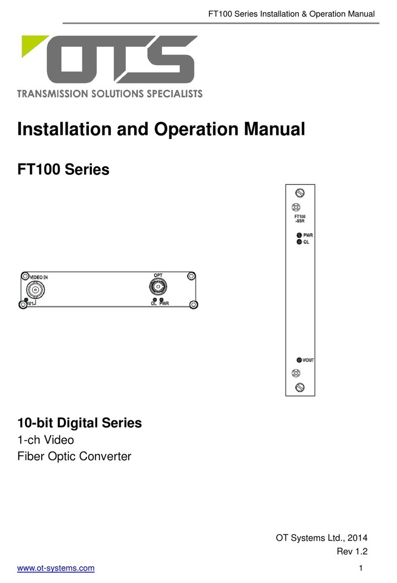
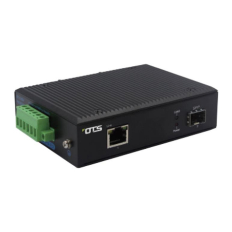
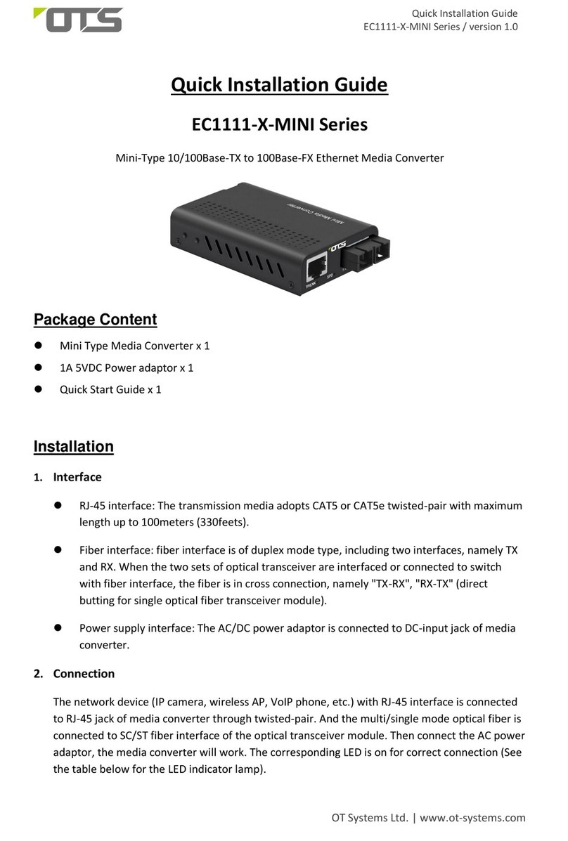
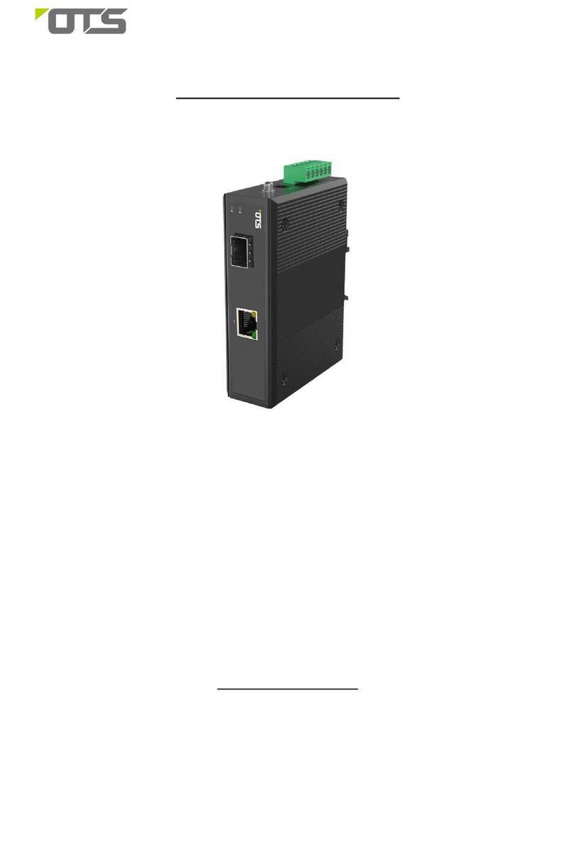
OTS ET1212Pp-S-DR User manual
Other OTS Media Converter manuals
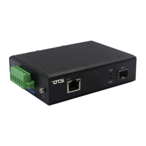
OTS
OTS ET1212-S-DR User manual
OTS
OTS FT800-SSTSA User manual
OTS
OTS FT010AB Series User manual
OTS
OTS ET1111PpH-S-DR User manual
OTS
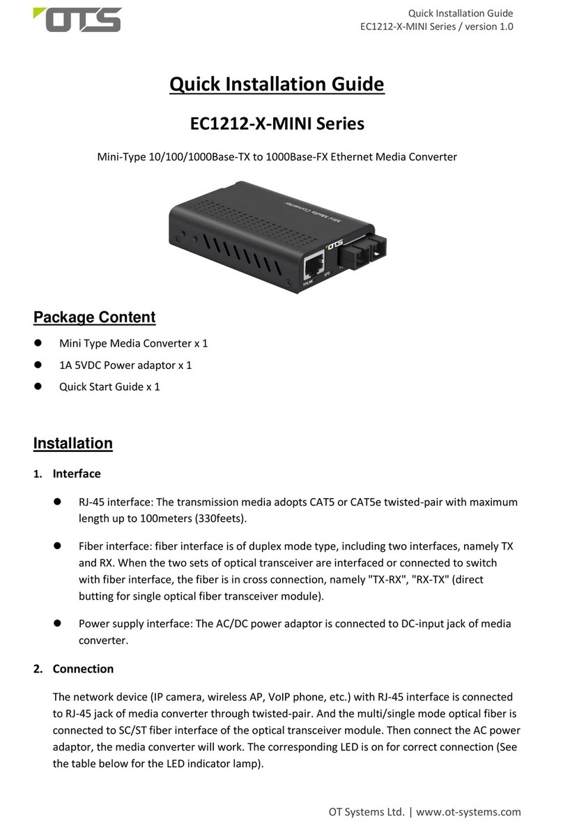
OTS EC1212-X-MINI Series User manual
OTS
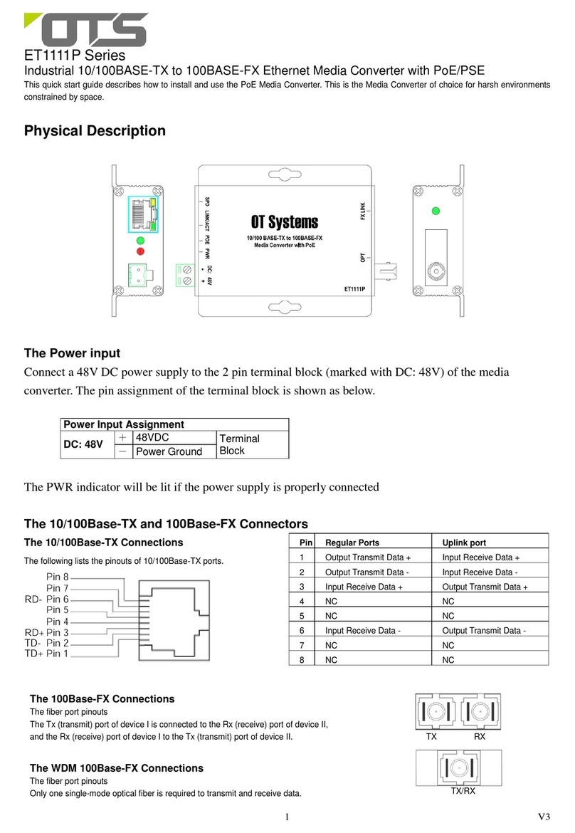
OTS ET1111P Series User manual
OTS
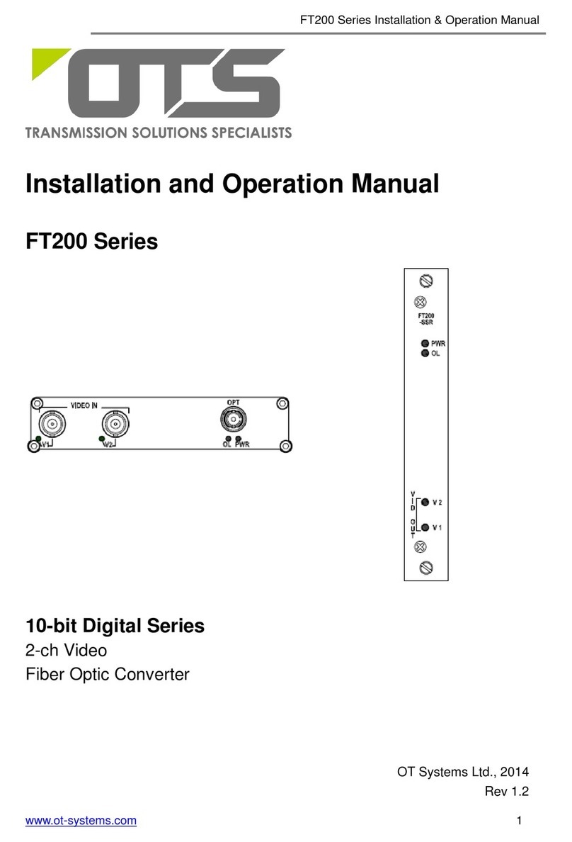
OTS FT200-SSTSA User manual
OTS
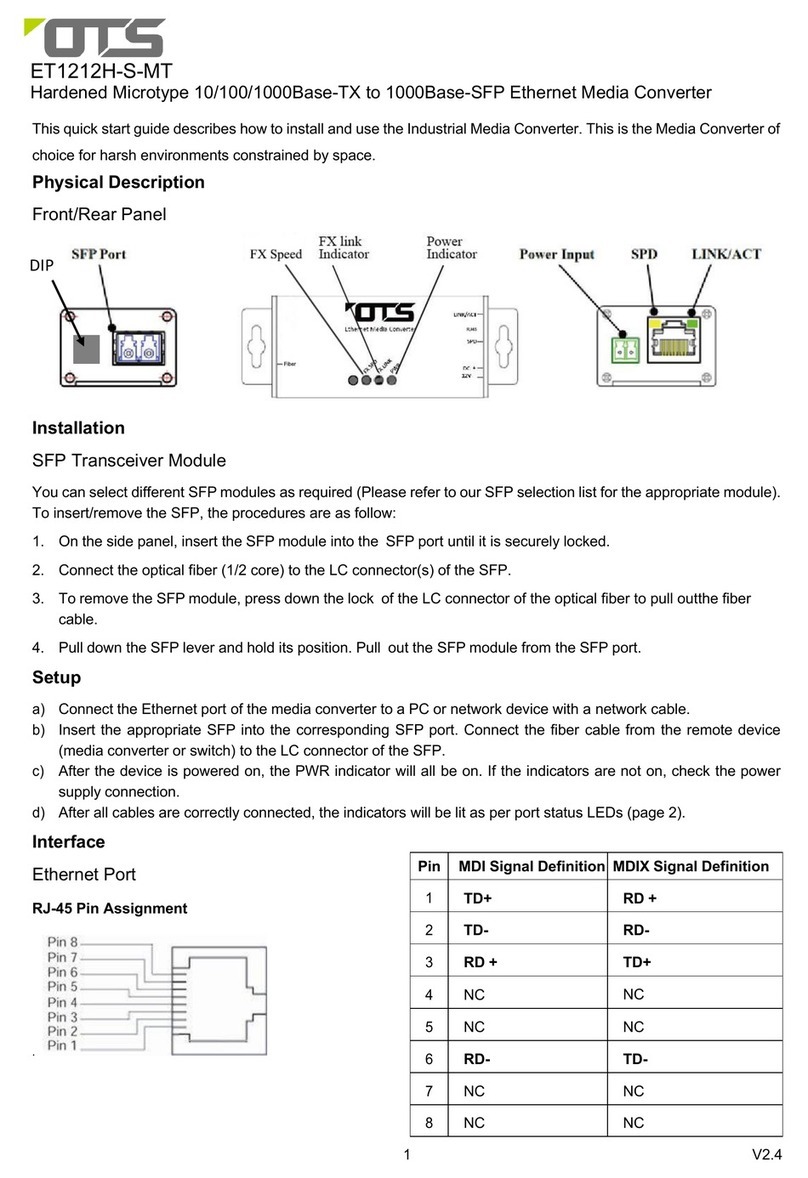
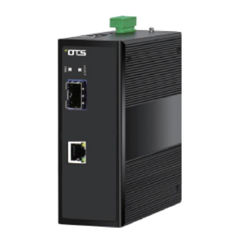
OTS ET1212H-S-MT User manual
OTS
OTS ET1212PpH-SA-DR User manual
OTS
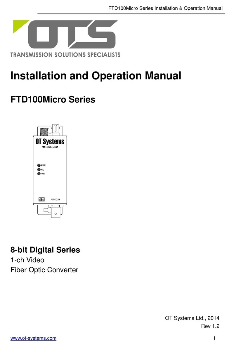
OTS FTD100Micro-SST User manual
Popular Media Converter manuals by other brands

H&B
H&B TX-100 Installation and instruction manual

Bolin Technology
Bolin Technology D Series user manual

IFM Electronic
IFM Electronic Efector 400 RN30 Series Device manual

GRASS VALLEY
GRASS VALLEY KUDOSPRO ULC2000 user manual

Linear Technology
Linear Technology DC1523A Demo Manual

Lika
Lika ROTAPULS I28 Series quick start guide

Weidmuller
Weidmuller IE-MC-VL Series Hardware installation guide

Optical Systems Design
Optical Systems Design OSD2139 Series Operator's manual

Tema Telecomunicazioni
Tema Telecomunicazioni AD615/S product manual

KTI Networks
KTI Networks KGC-352 Series installation guide

Gira
Gira 0588 Series operating instructions

Lika
Lika SFA-5000-FD user guide
