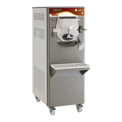
OTT FREEZER MASTERCHEF User manual

INSTRUCTION MANUAL
MASTERCHEF
MASTERCHEF S

-2-
MASTERCHEF
masterchef_G-07/07-ed.2
OTTFREEZER
ViaEmilia,45/A-40011AnzolaEmilia(Bologna)-Italy
Tel.051-6505330-Fax051-6505331
This handbook may not be reprinted, transferred, registered, recorded in a retrieval system, nor
translatedinotherlanguagesunlessotherwisepreviouslyagreedwith OTTFREEZER.
The purchaser has the wright to reprint it for his own office use.
OTT FREEZER policy pursues a steady reasearch and development, thus it reserves the right to
make changes and revisions whenever deemed necessary and without being bound to previous
statements to the purchaser.
We wish to thank you for the preference granted to us by purchasing one of OTT
FREEZER machines.
To thebest guarantee,since 1993 OTTFREEZER has submittedits own Quality
System to the certification according to the international Standard ISO 9001-94,
nowadays its production has got UNI-EN-ISO 9001-2000 Certified Quality
System.
Moreover,OttfreezermachinescomplywithfollowingEuropeanDirectives:
• 98/37/CE MachinesDirective;
• 73/23/CEE Low tension Directive;
• 89/336/CEE EMC Directive;
• 89/109/CEE Food Contact Directive.

MASTERCHEF
-3- masterchef_G-07/07-ed.2
GENERAL INDEX
FOREWORD ......................................................................................................................3
INSTRUCTIONHANDBOOK ............................................................................................. 5
PURPOSE ............................................................................................................................ 5
HANDBOOK STRUCTURE............................................................................................... 5
ADDITIONALDOCUMENTATION................................................................................... 5
SAFETY .............................................................................................................................. 6
QUALIFICATIONOFTHE STAFF.................................................................................... 6
CONVENTIONALSYMBOLS ............................................................................................ 7
WARNINGS ........................................................................................................................ 7
1 GENERAL
1.1 GENERALINFORMATION .........................................................................................9
1.1.1MANUFACTURER'SIDENTIFICATIONDATA.................................................. 9
1.1.2CLIENT/USER'SIDENTIFICATIONDATA.......................................................... 9
1.1.3INFORMATIONABOUTSERVICE ...................................................................... 9
1.1.4INFORMATIONTOTHE USERS......................................................................... 9
1.2 INFORMATIONABOUTTHEMACHINE .................................................................10
1.2.1GENERALINFORMATION ................................................................................ 10
1.2.2TECHNICALFEATURES .................................................................................... 11
1.2.3LOCATIONOFTHEMACHINEGROUPS .......................................................... 11
1.3 INTENDEDUSE .........................................................................................................12
1.4 NOISE .........................................................................................................................12
1.5 STORINGAMACHINE .............................................................................................12
1.6 DISPOSAL OF PACKING STUFFS ........................................................................12
2 INSTALLATION
2.1 ROOMNECESSARYTOTHEMACHINEUSE .........................................................13
2.2 MACHINELOCATION ..............................................................................................13
2.3 MACHINESWITHAIRCOOLEDCONDENSER ......................................................13
2.3.1WATERSUPPLYCONNECTION FORWASH .................................................. 13
2.4 MACHINESWITHWATERCOOLEDCONDENSER ...............................................14
2.4.1WATERVALVEADJUSTMENT ........................................................................ 14
2.4.2WATERSUPPLYCONNECTIONFORMACHINEWASH ................................ 15
2.5 ELECTRICCONNECTION ........................................................................................15
2.5.1REPLACINGTHEINPUTCABLE ....................................................................... 15
2.6 REFILLING .................................................................................................................16
2.7 MACHINETESTING ...................................................................................................16
2.8 MOVEMENT-TRANSPORT .....................................................................................16
DIRECTIONSFORUSE
3.1 MACHINESAFETYWARNINGS ..............................................................................17
3.2 MACHINECONFIGURATION ...................................................................................17
3.3 CONTROLS ...............................................................................................................18
3.3.1PUSHBUTTONPANEL ....................................................................................... 18
3.3.2STOPPUSH-BUTTON ........................................................................................ 18
3.3.3BEATINGPUSH-BUTTO .................................................................................... 19
3.3.4ADJUSTINGBEATERSPEEDPUSH-BUTTON.................................................. 19
3.3.5EXTRACTIONPUSH-BUTTON.......................................................................... 20
3.3.6HEATINGPUSH-BUTTON ................................................................................. 20
3.3.7COOLINGPUSH-BUTTON ................................................................................. 20
3.3.8"GO"PUSH-BUTTON ......................................................................................... 21
3.3.9INCREMENTPUSH-BUTTON ............................................................................ 21
3.3.10DECREMENTPUSH-BUTTON ......................................................................... 21
3.3.11TIMERPUSH-BUTTON .................................................................................... 21
3.3.12WASHINGPUCH-BUTTON.............................................................................. 22
3.3.13RECIPESPUSH-BUTTON ................................................................................. 22
3.3.\4RECPUSH-BUTTON.......................................................................................... 23

-4-
MASTERCHEF
masterchef_G-07/07-ed.2
3.4 PERSONALIZEDPROGRAMS .................................................................................23
3.4.1USERPROGRAMCREATION ............................................................................ 23
3.4.2EXAMPLEOF PROGRAMCREATION ............................................................. 24
3.4.3CANCELLINGAUSERPROGRAM .................................................................... 25
3.5 READINGPROGRAMS(AUTOMATICANDUSER)...............................................25
3.6 USERPROGRAMMING .............................................................................................26
3.7 MACHINESTART ......................................................................................................26
3.7.1AUTOMATICOPERATION ............................................................................... 26
3.7.2MANUALOPERATION ..................................................................................... 26
4. ALARMS.....................................................................................................................27
4.1 NOPOWERSUPPLY ............................................................................................. 28
5. CLEANING, DISASSEMBLINGANDREASSEMBLINGPARTSINCONTACT
WITHTHEPRODUCT ...............................................................................................31
5.1 PRELIMINARYCLEANING .................................................................................. 31
5.2 DISASSEMBLINGTHE SPIGOT .......................................................................... 31
5.3 DISASSEMBLINGTHETANKCOVER ................................................................. 32
5.4 DISASSEMBLINGTHEBEATER .......................................................................... 32
5.5 HYGIENE ............................................................................................................... 33
5.6SANITATION ........................................................................................................ 33
6. MAINTENANCE .........................................................................................................35
6.1 SERVICINGTYPOLOGY ..........................................................................................35
6.2 WATERCOOLING .....................................................................................................35
6.3 AIRCOOLING ............................................................................................................35
6.4 ORDERINGSPAREPARTS ......................................................................................35
7. TROUBLESHOOTGUIDE ..........................................................................................37
7.1 TROUBLESHOOTGUIDE..........................................................................................37

MASTERCHEF
-5- masterchef_G-07/07-ed.2
FOREWORD
INSTRUCTIONHANDBOOK
Editing this handbook, it was taken into due account community directions on safety standards
aswellasonfreecirculationofindstrialproductswithinE.C.(R.E.C.Councildirection89/392and
subsequent, known as "Machines Direction".
AIM
This handbook was edited while taking into due account needs of machine users.
Topics relevant to a correct use of the machine have been analyzed in order to keep unchanged
in the long run quality features of the worldwide OTT FREEZER machines.
A significant part of this handbook refers to the conditions necessary to the machine use and to
the necessary behaviour during cleanout as well as routine and special maintenance.
Nevertheless, this handbook cannot meet in details all demands; in case of doubts or failing
information, please apply to:
OTTFREEZER ViaEmilia,45/A-40011AnzolaEmilia(Bologna)-Italy
Tel.0516505330-Fax0516505331
HANDBOOKSTRUCTURE
This handbook is structurilized in sections, chapters and subchapters in order to consult it more
easily.
Section
A section is the part of handbook identifying a specific topic referred to a machine part.
Chapter
A chapter is that part of section describing a group or concept relevant to a machine part.
Subchapter
It is that part of a chapter detailing the specific component of a machine part.
It is necessary that each person involved in the machine running reads and clearly understands
those parts of the handbook of own concern, and particularly:
- TheOperatormust have alookatchaptersconcerning themachinestart-upandtheoperation
of machine groups.
-Askilledtechnicianemployedininstallation,maintenance,repair,etc.,must readallpartsof
this handbook.
ADDITIONALDOCUMENTATION
Along with an instruction manual, each machine is also supplied complete with further
documentation:
-Machineequipment:Alistofsparepartsdeliveredtogetherwiththemachineforitsmaintenance.
- Wiring diagram: A diagram of wiring connections put into the machine.
ATTENTION!!
Before using the machine read carefully the instruction handbook.
Pay attention to the safety instruction

-6-
MASTERCHEF
masterchef_G-07/07-ed.2
SAFETY
Whenusingindustrialequipmentandplants,onemustbeawareofthefactthatdrivemechanisms
(rotarymotion),highvoltagecomponents,aswellaspartssubjecttohightemperaturesmaycause
serious damages to persons and things.
Who is in charge of plant safety must be on the look-out that
- an uncorrect use or handling is avoided
- Safety devices must neither be removed nor tampered
- Only original spare parts are to be used especially as far as those components with safety
functions are concerned (ex.: protection microswitches, thermostats).
To achieve the above, the following is necessary:
- At working place an instruction manual relevant to the machine should be available.
- Such documentation must be carefully read and regulations must consequently be followed.
- Only adequately skilled personnel will have to be assigned to electrical equipment.
QUALIFICATIONOFTHESTAFF
Staff attached to the machine can be distinguished according to training and responsibility as
follows:
OPERATOR
- A person who has not necessarily a high technical knowledge, just trained for ordinary
operation of the machine, such as: startup, stop, filling, basic maintenance (cleanout, simple
blocking, instrumentation checkings, etc.).
SKILLEDENGINEER
-A personengangedon morecomplicatedoperations ofinstallation, maintenance, repairs,etc.
IMPORTANT!
Onemustbeonthelook-out that thestaffdoesnotcarryoutanyoperationoutsideitsownsphere
of konwledge and responsibility.
NOTE:
According to the standard at present in force, a SKILLED ENGINEER is who, thanks to
- training, experience and education,
- knowledge of rules, prescriptions and interventions on accident prevention,
- knowledge of machine operating conditions,
is able to realize and avoid any danger and has also been allowed by the person in charge of
plant safety to carry out all kinds of interventions.

MASTERCHEF
-7- masterchef_G-07/07-ed.2
CONVENTIONALSYMBOLS
ATTENTION:ELECTRICSHOCKDANGER
The staff involved is warned that the inobsevance of safety rules in carrying out the operation
described may cause an electric shock.
ATTENTION:GENERALDANGER
The staff involved is warned that the operation described may do harm if not carried out in the
observarnce of safety rules.
NOTE
It points out significant information for the staff involved.
WARNINGS
The staff involved is warned that the inobservance of information may cause a loss of data and
damages to the machine.
MACHINEOPERATOR
It deals with an unskilled person , who has no specific competences and can only carry out easy
functions, such as the machine operation by means of controls available on push-button panel
, and filling and drain of products used during production.
MAINTENANCEENGINEER
Heisa skilled engineer for operation of themachineunderregular conditions; he is able to carry
outinterventionsonmechanicalpartsandall regulations,aswellasmaintenanceandrepairs. He
is qualified for interventions on electrical and freezing plants.
OTTFREEZERENGINEER
It deals with a skilled engineer the manufacturer puts at clients' disposal for complicated
interventionsundparticularconditionsor anyhowin accordancewithagreementstakenwith the
machine's user.
PROTECTIONS
This symbol placed by description side means that the operator must use personal protections
against an implicit risk of accident.
WARNING
Wheninstalling the machine, insertadifferential magnetothermal protectionswitchon all poles
oftheline,adequatelysizedtotheabsorptionpowershownonmachine dataplateandwithcontact
opening of 3 mm at least.
- Neverputyourhandintothemachine,alikeduringproductionandcleaningoperations.Before
carrying out any maintenance operation, make sure that the machine is in “STOP” position
and main switch has been cut out.
- It is forbidden to wash the machine by means of a bolt of water under pressure.
- Itisforbiddentoremovepanelsinordertoreachthemachineinsidebefore disconnectingthe
machine.
-OTT FREEZER is not responsible for any accident that might happen during operation,
cleaning and/or servicing of its units, if this warning has not been fully complied with.

-8-
MASTERCHEF
masterchef_G-07/07-ed.2

MASTERCHEF
-9- masterchef_G-07/07-ed.2
1. GENERAL
1.1 GENERALINFORMATION
1.1.1Manufacturer'sidentificationdata
The machine has a data plate carrying manufactuer's data, machine type and identification number
given when it is manufactured.
1.1.2Client/user'sidentificationdata
CLIENT: ..............................................................................................................
ADDRESS: .........................................................................................................
TELEPHONE:......................................................................................................
Machineserialnumber: ......................................................................................
Machine delivered on:........................................................................................
Instr. handbook delivered on: ............................................................................
1.1.3Informationaboutservice
All operations of routine maintenance are described in section "Maintenance" of this
handbook; any further operation requiring radical interventions on the machine must be agreed
with the manufacturer, who will also examine the possibility of a direct action on the spot.
1.1.4Informationtotheuser
- The manufacturer of the machine here described is at user's disposal for any explanation and
information about the machine operation.
- In case of need, the interlocutor is the distributor being present in user's country, or the
manufacturer if no distributor is in that market.
- Manufacturer's service department is at clients' disposal for any information about operation,
and requests of spare parts and service.
- The manufacturer reserves the right to carry out all machine changes deemed as opportune
without previous notice.
- Descriptions as well as pictures contained in this handbook are not binding.
- Reproduction rights are reserved to OTT FREEZER
VHzkW
A
Gas kg
Cod.
ANZOLA EMILIA - BOLOGNA - ITALY
Matr.
AB
CDE H
FG
I
100089654588-4
A=Serialnumber
B=Machine type
C= Voltage
D= Fuse Current
E= Gas type and weight
F= Machine code
G= Condensation
A=AirW=Water
H= Frequency
I=Power input

-10-
MASTERCHEF
masterchef_G-07/07-ed.2
1.2 INFORMATION ABOUT THE MACHINE
1.2.1Generalinformation
Masterchef machines produce ice cream and confectionery and they can work fruit and greens
in pieces.
This machine was not designed:
- to produce "pasta"
- to freeze water, i.e., to produce ice cream with high water contents
- to mix, work out, etc. explosives or substances prejudicial to the health.
OTTFREEZERrecommends toalwaysusehighqualityingredientsforconfectioneryproducts
in order to satisfy your customers, even the hardest-to-please ones. Any saving made to the
prejudice of quality will surely turn into a loss much bigger than the saving itself.
Bearing in mind the above statements, please take heed of the following suggestions:
zChoose high quality natural ingredients or buy them from reliable companies.
zClosely follow instructions given by your supplier.
zDo not alter your supplier's recipies, by adding, for instance, water or sugar.
zTaste your product before serving and start selling it if only entirely satisfactory.
zMake sure your staff always keeps the machine clean.
zHave your machine always serviced by companies authorized by OTT FREEZER.
RESIDUALRISKS
Dangerofthermalnature
By opening the cover of the tank containing high temperature product, the
operatorrunstheriskofbeingcaughtinhotsteam.
Actwithutmostcareanduseproperprotectionsbeforeopeningthe
tankcover.

MASTERCHEF
-11- masterchef_G-07/07-ed.2
1.2.2Technicalfeatures
* Other voltages and cycles available
** Models also available in aircooled execution
Performances refer to a room temperature of 25°C and to 20°C temperature of condensing water
1.2.3Locationofthemachinegroups
COVER
CONTROL
PANEL
ICECREAM
OUTLET
SHELF FOR
DRIP TRAY
A
C
B
LEDOM
ylruoH tuptuo knaT yticapac *rewopcirtcelE dellatsnI rewop snoisnemiDthgieW
.lsertiLtloVselcyCsesahPWkhtdiW .mm )A(
htpeD .mm )B(
thgieH .mm )C( .gKteN
fehcretsaM 5,25÷5,22 7 004 05 3 2,5 505 007 0821 091
SfehcretsaM 09÷5,7321004053 7,70550470931562

-12-
MASTERCHEF
masterchef_G-07/07-ed.2
1.3 INTENDED USE
Masterchef mustonly beused conformingwithcontentsofparagraph1.2.1"GeneralInformation",
within the functional limits hereunder reported:
Voltage: ±10%
Airmin.temperature: 10°C
Airmax.temperature: 43°C
Watermin.temperature: 10°C
Watermax.temperature: 30°C
Water min. pressure: 0,1MPa(1bar)
Watermax.pressure: 0,8MPa(8bar)
Maxairrelativehumidity: 85%
- Thismachinehasbeendesignedfor itsuseinroomsbeingnotsubjecttoexplosion-proof laws;
its use is thus bound to complying rooms and normal atmosphere.
- The machine must not be used in the open air, at the risk of rain.
- The machine must be used in lying flat and with castors locks engaged.
- The machine must only be used by the operators.
- The machine may not be washed with any direct water spray.
1.4 NOISE
The continuous level of acoustic radiation pressure, which has been weighed and called A on
working place, turns to be lower than 70 dB(A), both by aircooled and by watercooled units.
1.5 STORING A MACHINE
The machine must be stored in a dry and dump-free place.
Before storing the machine, wrap it in a cloth in order to protect it against dust and else.
1.6 DISPOSAL OF PACKING STUFFS
When opening the packing crate, divide packing stuffs per type and get rid of them according
to laws in force in machine installation country.

MASTERCHEF
-13- masterchef_G-07/07-ed.2
2. INSTALLATION
2.1 ROOM NECESSARY TO THE MACHINE USE
The machine may only run indoors.
The machine must be installed in lying flat, so that air can freely circulate all around.
Rooms fortheapproachtothemachinemustbeleftfreeinordertoenabletheoperator toact without
constraint and also to immediately leave working area, if need be.
Theminimumapproach roomtoworkingareashouldbeatleast 150cminconsiderationof space
taken by opened doors.
2.2 MACHINE LOCATION
The machine is provided with wheels for its easy location; two castors are provivded with
mechanical locks, which once engaged, lock the wheels and so keep the machine standstill.
2.3 MACHINES WITH AIRCOOLED CONDENSER
Machines with aircooled condenser must be installed no closer than 50 cm to any wall in order to
allow free air circulation around the condenser.
Frequently clean the floor beneath and near to the machine, to avoid that paper and else obstruct
a regular airflow. Further, condenser needs to be cleaned monthly, so eliminating dust, paper and
what else can obstruct it and affect a regular operation.
NOTE
An insufficient air circulation affects operation and output capacity of the machine.
2.3.1 Watersupplyconnectionforwash
Themachine must beconnectedto running waterwhichpressure must notbehigher than 0,8MPa
(8bar).
Byaircooledmachines,waterconnectionfordrinkingwater(formachinewash),markedbytheplate
herebelow, is placed under the machine.
Connect this tube to drinkable water,only.
For an easy cleaning, we advise you to install a shut-off valve between machine and warm water
used in laboratory.
IN
10
water
air
60

-14-
MASTERCHEF
masterchef_G-07/07-ed.2
2.4 MACHINES WITH WATERCOOLED CONDENSER
By watercooled machines wash water and gas cooling connections are on the back panel.
There are three connections aligned on the same vertical.
Watercooledmachinescanonlyrunwhenconnectingthemtorunningwatersupplyortocooling
towers.
Watermusthaveapressureo0,1MPa(1bar)atleast,andadeliveratleasteequaltotheestimated
hourly consumption.
Connect inlet pipe marked by the plate "Entrata Acqua" (water inlet) to water supply, instlaling
a shut-off valve and the outlet pipe marked by "Uscita Acqua" (water outlet) to a drain pipe,
installing a shut-off valve, too.
We recommend to use rubberized canvas tubes with a working pressure up to 0,8 MPa (8 bar).
2.4.1 Watervalveadjustment
IMPORTANT
If water valve needs to be reset, such an operation must be carried out by skilled personnel, only.
Set water valve so that, with machine off no water comes out and lukeawarm water flows out
when on.
Waterconsumption
Estimated water consumption per hour is shown in the table.
NOTE:
Water consumption increases if temperature of entering water is above 20°C.
ATTENTION
Donotleavethemachineinaroomwithtemperaturebelow0°Cwithoutfirstdrainingwater
fromcondenser(seeSection5).
Water inlet
Water outlet
+-
Washing water
inlet

MASTERCHEF
-15- masterchef_G-07/07-ed.2
2.4.2Watersupplyconnectionformachinewash
Alike aircooled and watercooled machines have been provided with a separate inlet pipe for
washingwater. Onlyhas drinkingwater tobe connectedto thispipe, whichis markedby theplate
shown herebelow.
Tomakecleanouteasy,werecommendtoconnectwarmwaterusedinyourlaboratorydirectlyto
wash pipe, installing a shut-off valve.
2.5 ELECTRICAL CONNECTION
Before connecting the machine to the mains, check that the voltage is the same as the one stated
on its plate.
Power cable by machines on 400 V, 50 Hz, threephase is made up of 5 wires: 3 wires for phases,
the blue one for neutral and the green/yellow one for earthing.
By machines with other voltages, power cable is made up of 4 wires, without the neutral one.
Betweenthemachineandthemains,insertamagnetothermicdifferentialsectioningswitchproperly
dimensioned to the input required, and having a contact opening of 3 mm, at least.
IMPORTANT
Yellow/green ground wire must be connected to a good ground plate.
2.5.1 Replacingtheinputcable
Should the main cable of the machine be damaged, it needs to be replaced immediately through
a cable with similar features. Replacement shall be carried out by skilled technicians, only.
IN
ledoM dellatsnI rewop Wk
fehcretsaM 2,5
SfehcretsaM7,7

-16-
MASTERCHEF
masterchef_G-07/07-ed.2
2.6 REFILLING
Motor installed in the machine is of the type with lubrication for life; no action of checking/
replacing or topping up is necessary.
Gas filling necessarytothefreezingsystem iscarriedout at OTTFREEZERworksduringmachine
postproduction testing.
If a gas addition happens to be made, this must be carried out by skilled technicans, only, who
can also find out trouble origin.
2.7 MACHINE TESTING
Apostproduction test ofthemachine is carriedout at Ottfreezerpremises; Operation andoutput
functionality of the machine are thoroughly tested.
Machinetestat enduser'smustbecarriedoutbyskilledtechniciansorbyoneof OTTFREEZER
engineers.
After the machine positioning and correct connections, also carry out all operations necessary
to functional check and test of the machine.
2.8 MOVEMENT - TRANSPORT
Should the machine need be moved from its original location, it is necessary to turn to skilled
personnel.

MASTERCHEF
-17- masterchef_G-07/07-ed.2
3. DIRECTIONSFORUSE
3.1 MACHINE SAFETY WARNINGS
Whenusingindustrialequipmentand plants,onemustbeaware ofthe factthatdrivemechanisms
(rotarymotion),highvoltagecomponents,aswellaspartssubjecttohightemperaturesmaycause
serious damages to persons and things.
Who is in charge of plant safety must be on the look-out that
- an uncorrect use or handling is avoided
- Safety devices must neither be removed nor tampered
- Only original spare parts are to be used especially as far as those components with safety
functions are concerned (ex.: protection microswitches, thermostats).
To achieve the above, the following is necessary:
- At working place an instruction manual relevant to the machine should be available.
- Such documentation must be carefully read and regulations must consequently be followed.
- Only adequately skilled personnel will have to be assigned to electrical equipment.
3.2 MACHINE CONFIGURATION
Themachineconsistsofa transmissionof movement for beaterassembly,a heatingandcooling
system with aircooled or watercooled condenser.
The product is prepared by pouring a mix into the tank and starting the production cycle, while
referringtominimumandmaximum quantitiesreportedinSection1, tableon page49.
As the machine is provided with specific programs for the preparation of various products, one
must set the program relevant to the selected product before starting the cycle.
When the cycle ends, the product can be drawn out from the special spigot, by pressing the di
EXTRACTIONpush-button.

-18-
MASTERCHEF
masterchef_G-07/07-ed.2
3.3 CONTROLS
3.3.1 Controlpanel
Foracorrectuseofcommandsonkeypad,pressonthesymboloranywayinthemiddleofthekey.
3.3.2Stoppush-button
In this function the machine is stopped and the relative LED is ON.
From the Stop position you can access any machine function.
WhenthemachineisSTOPPEDthedisplayindicatesthetimeandthedayoftheweekonthefirst
line, and the date and the TEV on the second line.
E.g.:
11:15:08 MON
23/10 +11°
THESTOPPUSHBUTTONISALSOUSEDTORESETANYALARM.
As well as stopping any function if you hold the pushbutton down for 5 seconds you enter into
the technical program (described below).

MASTERCHEF
-19- masterchef_G-07/07-ed.2
3.3.3Beatingpush-button
This key activates the tank beater.
The display shows time and day of the week on the first line.
On the second line, on the left the number of the speed appears, and on the right the
temperatureofthemixture in the tub (TEV) appears:
11:15:08MON
set +07°
The beater motor is controlled by an Inverter.
For this reason the beating is divided into 7 speed steps with the possibility
of setting speed 0 (beater stopped).
1 is associated with the lowest speed while 7 is the fastest.
Press Beating key once and you access the function, and the relative LED switches ON in
fixed mode and the last speed set is activated.
Once the beating has started it can be modified by pressing first the Beater Speed Adjustment
key. The Increase and Decrease LEDs switch ON. The display continues to display:
11:15:08MON
set +07°
At this point the speed can be modified (one step at a time) with Increase and Decrease keys.
The first character on the second line of the display indicates the speed:
Speed0 (static) Speed1 Speed2 Speed3 Speed4 Speed5 Speed6 Speed7.
When beating is active press again and beating stops
3.3.4Adjustingbeaterspeedpush-button
The function is only active when the Beater function has been selected.
Press Beater Speed Adjustment button to select the desired speed, using Increase and
Decrease buttons.
As described above, the first character on the second line of the display indicates the speed:
Speed0 (static) Speed1 Speed2 Speed3 Speed4 Speed5 Speed6 Speed7.

-20-
MASTERCHEF
masterchef_G-07/07-ed.2
3.3.5Extractionpush-button
The display shows:
11:15:08MON
set +07°
Press Extraction button The beater goes to maximum speed (even if the display shows the last
speed selected).
One can also obtain a Cooled Extraction by pressing Cooling key during the extraction. In this
way, one activates cooling which will end after a timer of 20 seconds stops.
3.3.6Heatingpush-button
When you press the Heating pushbutton the Beater starts at the last speed set.After a 2 sec pause
the hot is also activated
When you press the Beater Speed Adjustment pushbutton you can select a speed from the seven
available as described in paragraph “Adjusting Beater Speed” or also To deselect it by pressing
Beater once to obtain static heating.
Heating may also be deactivated by pressing Heating pushbutton. In this way you can have
beatingwithoutheating(theLEDswitchesOFF andthe heatisdeactivated). Ifyoupress heating
again the heat is activated and the previously selected speed remains active.
The heat remains active until the temperature set on the display is reached.
The display shows:
11:15:08MON
set+85° +21°
TheTemperatureSetcan be modified with Increment and Decrement keys 10 to 120°C.
Its typical value is 85°C.
Todisplaytemperaturesover99°Cthe“+”iseliminated:
11:15:08MON
set105° +21°
The heating temperature is memorised and the next time the last Set will be set again.
3.3.7Coolingpush-button
When you press the cooling pushbutton the display shows the last temperature set, while on the
right hand side you can see the current temperature of the mixture in the drum (TEV).
11:15:08 MON
set+04° +22°
The cooling function starts up the beating at the last speed set. After a two second pause
the cooling is activated.
ThetemperaturemaybechangedusingIncreaseandDecreasebuttonsfrom2to105°Cthetypical
value set is 4°C.
Beatingspeed may bechangedby pressing theBeaterSpeed AdjustmentbuttonAdjustin Beater
Speed as described in paragraph “Adjusting Beater Speed”.
When you press Beater it switches OFF. In this case you obtain static cooling.
Cooling will be active till the programmed Temperature Set on display is reached.
This manual suits for next models
1
Table of contents