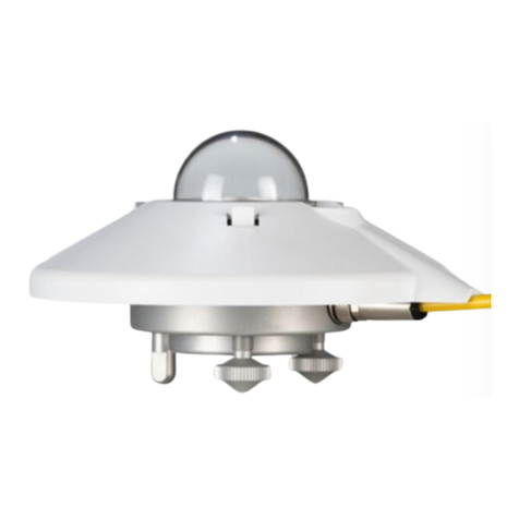
OTT HydroMet KIPP & ZONEN SMP12 User manual

Confidential - Company Proprietary
Instruction Manual
SMP12 • Smart Pyranometer

2
Confidential - Company Proprietary
Important user information
Dear customer, thank you for purchasing a Kipp & Zonen instrument. It is essential that you read this manual completely
for a full understanding of the proper and safe installation, use, maintenance and operation of your new SMP12 Smart
pyranometer.
We understand that no instruction manual is perfect, so should you have any comments regarding this manual we will
be pleased to receive them at:
OTT HydroMet B.V.
Delftechpark 36, 2628 XH Delft, - or
P.O. Box 507, 2600 AM Delft,
The Netherlands
+31 15 2755 210
www.kippzonen.com
Warranty and Liability
OTT HydroMet B.V. guarantees that the product delivered under the Kipp & Zonen brand name has been thoroughly
tested to ensure that it meets its published specifications. The warranty included in the conditions of delivery is valid
only if the product has been installed and used according to the instructions supplied by OTT HydroMet B.V.
OTT HydroMet B.V. shall in no event be liable for incidental or consequential damages, including without limitation, lost
profits, loss of income, loss of business opportunities, loss of use and other related exposures, however incurred, rising
from the faulty and incorrect use of the product.
Modifications made by the user may affect the instrument performance, void the warranty, or affect the validity of the
CE declaration or other approvals and compliances to applicable International Standards.
Copyright © 2022 OTT HydroMet B.V.
All rights are reserved. No part of this publication may be reproduced, stored in a retrieval system or transmitted, in any
form or by any means, without authorization by OTT HydroMet B.V.
OTT HydroMet B.V. reserves the right to make changes to this manual, brochures, specifications and other product
documentation without prior notice.
Manual Document Number: V2201-01
Publication date: January-2022

3
Confidential - Company Proprietary
Table of Contents
Contents
Important user information..............................................................................................................................................2
Introduction ......................................................................................................................................................................6
Safety precautions.................................................................................................................................................6
Waste disposal- WEEE directive 2012/19/EU.........................................................................................................6
Product overview ..............................................................................................................................................................7
The SMP12 pyranometer .......................................................................................................................................7
Included with the product.....................................................................................................................................8
Intended use ..........................................................................................................................................................8
International Standards ........................................................................................................................................8
Operation, measurement and background......................................................................................................................9
Data collection.......................................................................................................................................................9
Remote management............................................................................................................................................9
Key parts of the SMP12 pyranometer..................................................................................................................10
Dome...............................................................................................................................................................10
Diffuser............................................................................................................................................................10
Thermopile......................................................................................................................................................10
Housing ...........................................................................................................................................................11
Desiccant.........................................................................................................................................................11
Cable and connector.......................................................................................................................................11
Specifications..................................................................................................................................................................12
Optical and electrical...........................................................................................................................................12
Dimensions and weight .......................................................................................................................................13
Planning the installation of the SMP12 ..........................................................................................................................14
Where to place SMP12 in the PV plant ................................................................................................................14
Installation ......................................................................................................................................................................15
Tools required......................................................................................................................................................15
Pre-check .............................................................................................................................................................16
Pre-installation ....................................................................................................................................................16
Connecting in the office.......................................................................................................................................16
Changing the settings of the SMP12....................................................................................................................18
Finding the COM port for the USB-RS-485 converter.....................................................................................18
First start up....................................................................................................................................................18
Configuring the settings .................................................................................................................................19
Main Window –Setup .....................................................................................................................................19
Main window –Configuration and changes to it............................................................................................20
Finding a SMP12 with unknown communication parameters ......................................................................21
Proper installation for measurement of global horizontal irradiance (GHI)......................................................24

4
Confidential - Company Proprietary
Location ..........................................................................................................................................................24
Mounting.........................................................................................................................................................24
Horizontal orientation ....................................................................................................................................25
Horizontal levelling of the instrument ...........................................................................................................25
Fitting the connector and cable .....................................................................................................................26
Fitting the sun shield ......................................................................................................................................26
Installation for measurement of tilted (POA) global irradiance.........................................................................27
Tilted installation of the instrument ..............................................................................................................28
Fitting the connector and cable .....................................................................................................................29
Fitting the sun shield ......................................................................................................................................29
Installation for measurement of reflected global irradiance .............................................................................30
Installation for measurement of albedo .............................................................................................................31
Installation for measurement of diffused horizontal irradiance (DHI)...............................................................31
Electrical connections.....................................................................................................................................................32
Power connection................................................................................................................................................33
Power consumption ............................................................................................................................................33
Allowed power supply voltages with cable losses in mind............................................................................34
Connecting to a RS-485 network.........................................................................................................................35
Recommended cable types.................................................................................................................................36
SMP12 EMC and Surge protection details...........................................................................................................36
Maintenance and re-calibration .....................................................................................................................................37
Recommended weekly maintenance..................................................................................................................37
Recommended monthly maintenance ...............................................................................................................37
Recommended yearly maintenance ...................................................................................................................37
Calibration –Recommended every 2 years.........................................................................................................37
Calibration traceability to the WRR................................................................................................................37
Trouble shooting ......................................................................................................................................................38
Output signal not present or incorrect ...............................................................................................................38
Accessories ...............................................................................................................................................................39
Diffuse radiation measurement ..........................................................................................................................39
Mountings ............................................................................................................................................................39
Glare screen kit ....................................................................................................................................................39
Cables...................................................................................................................................................................39
Frequently Asked Questions ....................................................................................................................................40
Customer support.....................................................................................................................................................42
Appendices ...............................................................................................................................................................43
Modbus®...............................................................................................................................................................43
Commonly used Modbus® commands................................................................................................................43
Commonly used input registers ..........................................................................................................................44
Input register details ...........................................................................................................................................45
5
Confidential - Company Proprietary
Read-write Holding registers...............................................................................................................................46
Holding register details .......................................................................................................................................46
Copyright notices.................................................................................................................................................48
Using this table
Click on any item in the table of contents to be taken directly to the relevant page.
Click on the bottom of any page to be taken back to the table of contents.

6
Confidential - Company Proprietary
Introduction
Reading this entire manual is recommended for a full understanding of this product.
CAUTION
The triangle with exclamation mark is intended to alert the user to the presence of important installation,
operating and maintenance instructions in the literature accompanying the instrument.
WARNING Low voltage electrical equipment
This low voltage electrical equipment should only be installed and serviced by authorized personnel, meaning
people who have been trained and designated as “authorized” by their employers.
Note : Useful information for the user
Safety precautions
Do not use this equipment for measurements other than the rated measurement category.
Many hazards are associated with installing and maintaining instruments on towers or elevated structures. It is advised
to use qualified personnel for installation and maintenance. The client is responsible for following the local safety
regulations. The use of appropriate equipment and safety practices is mandatory. Check your company's safety procedure
and protective equipment prior to performing any work. If the SMP12 is mounted at a high position, special care must be
taken to secure both the person installing it and the instrument from falling during installation.
The manufacturer is not responsible for any damages due to misapplication or misuse of this product including, without
limitation, direct, incidental and consequential damages, and disclaims such damages to the full extent permitted under
applicable law. The user is solely responsible to identify critical application risks and install appropriate mechanisms to
protect processes during a possible equipment malfunction.
CAUTION Risk of burns due to hot surface at high ambient temperature
The metal parts of the SMP12 housing can become very hot at high ambient temperatures.
This can result in burns.
Wear appropriate gloves during installation and maintenance.
While every attempt is made to get the highest degree of safety in our products, the client assumes all risk from injuries
resulting from improper installation, use or maintenance of the SMP12.
Waste disposal- WEEE directive 2012/19/EU
The pictogram showing a waste bin with a cross means that the product is subject to European Union
regulations covering segregated waste disposal. Thisapplies both to the product itself and to anyaccessories
marked with the same symbol. Disposal of any such item as unsorted domestic waste is not allowed.

7
Confidential - Company Proprietary
Product overview
This manual, together with the instruction sheet, and the Smart Explorer manual, provides information related to the
installation, maintenance, calibration, product specifications and applications of the SMP12 pyranometer. If any
questions should remain, please contact your local OTT HydroMet representative or e-mail the Kipp & Zonen customer
and product support department at: [email protected]. Please go to www.kippzonen.com for information
about other Kipp & Zonen products, or to check for any updates to this manual or software.
The SMP12 pyranometer
The SMP12 is a high quality pyranometer designed for measuring solar irradiance on a plane surface (radiant flux,
W/m²), which results from combination of the direct solar radiation and the diffuse sky radiation. The measurement can
be made horizontally for Global Horizontal Irradiance (GHI) or tilted for Global Tilted Irradiance (GTI).
The SMP12 can also be used to create an albedometer to measure surface reflectance where one SMP12 is facing the
ground and another SMP12 is facing the sky.
The SMP12 features:
•A diffuser based thermopile solar measurement sensor, fully compliant with ISO 9060:2018 Fast Response
Spectrally Flat Class A and with IEC 61724-1: 2021 for Class A PV plant monitoring
•Integrated dome heating with no moving parts to prevent dew and frost
•Enhanced surge protection on the data and power lines
•Remote tilt sensor to monitor the correct installation angle
•Internal relative humidity measurement to check the proper functioning of the internal desiccant
•Industry standard RS-485 Modbus® RTU communication
Internal digital signal processing and interfaces are optimised for industrial data acquisition and control systems. Kipp &
Zonen has developed a smart interface that features RS-485 Modbus® data communication for connection to
programmable logic controllers (PLC’s), inverters, digital control equipment and the latest generation of data loggers
and SCADA systems.
To achieve the required spectral and directional characteristics, the SMP12 uses a diffuser, optical filter, thermopile
detector and high quality glass dome. The SMP12 has a built-in bubble level and adjustable levelling feet. The snap-on
sun shield reduces solar heating of the housing.
The pyranometers are typically delivered with a waterproof plug pre-wired to a high quality signal cable, typically this is
10m long but other lengths are available. The instruments can also be ordered without a cable or with a plug only, for
the user to fit their own cable.

8
Confidential - Company Proprietary
Included with the product
The following items are included with the SMP12 pyranometer:
1SMP12 Smart Pyranometer
2Sun shield
3Optional cable 10, 25, 50, 100m pre-wired with 8-pins connector and connector-only available for customer to build
their own cable
4ISO 9060:2018 compliant calibration, directional response and temperature dependency certificate
5Instruction sheet
6Smart pyranometer fixing kit; 2 each of stainless steel M5 x 80 mm screw, nut, flat washer, nylon insulation rings.
Intended use
The SMP12 instrument is designed to measure and report solar irradiance, sensor body temperature, internal humidity
and tilt angle from horizontal.
The SMP12 can be mounted on a pole, cross-arm, or next to PV modules in a PV plant.
Communication is via Modbus® RTU using RS485 2-wire and the power supply needed is 10 to 30 VDC.
International Standards
The SMP12 is fully compliant with the requirements of ISO 9060:2018 for a Class A spectrally flat Pyranometer.
Spectrally Flat is the standard for Performance
Ratio input as it records all wavelengths reaching
the earth, from sunrise to sunset. Including the
spectrum valuable to PV modules.
The SMP12 complies with IEC 61724-1:2021
“Photovoltaic system performance –Part 1:
Monitoring” Class A instruments as it does not
need external heating and ventilation to prevent
morning dew and frost.
The SMP12 pyranometer is calibrated in
accordance with Annex A.3 of ISO 9847
‘Calibration of Field Pyranometers by Comparison to a Reference Pyranometer’. Annex A.3 refers to ‘Calibration Devices
Using Artificial Sources’. Calibrations are traceable to the World Radiometric Reference (WRR) in Davos, Switzerland.
2
4
2x
2x
2x
2x
6
5
3
1

9
Confidential - Company Proprietary
Operation, measurement and background
.
The SMP12 only requires a suitable source of power and radiation (light) to operate and make measurements. However,
it is necessary to connect them to some sort of readout or data storage device in order to save the measurements, as there
is no internal data memory.
Data collection
An often used setting for the solar irradiation data interval is to sample every second and store one minute averages. For
setting up the combination of pyranometer and data storage please refer to the manual of your data collection device.
Remote management
Since the SMP12 offers extra data from the standard measurements and error registers we recommend to read and log
the following registers:
•Instrument body temperature: A temperature between 5 and 15 °C higher than ambient, depending on local weather
conditions like wind, indicates a properly functioning heating system.
•Instrument tilt angle: For a fixed pyranometer (GHI or POA) any short term change >1° from the value recorded just
after installation, would require attention. The higher threshold helps to eliminate any influence of e.g. strong winds
or mounting material expansion and contraction due to temperature changes
For long term management an average is suitable and any change >0.2° would require attention.
•Instrument internal relative humidity (RH%): Since the internal volume is small and RH% is very much temperature
and desiccant dependent, the value will fluctuate over the day and that is no reason for alarm.
It is advised to measure the RH% over longer periods of time (months-years) during the cooler part of the day, above
freezing point and when possible at roughly the same reported body temperature (e.g. around midnight).

10
Confidential - Company Proprietary
Key parts of the SMP12 pyranometer
The detector of the SMP12 is based on a passive thermal sensing element called a thermopile. Although the detector
construction differs between models, the fundamental working principle is applicable to all SMP pyranometers.
The thermopile responds to the total incoming energy through the diffuser, which is non-spectrally selective. The
thermopile warms up and the heat generated flows through a thermal resistance to a heat-sink, the pyranometer housing.
The temperature difference across the thermal resistance of the detector is converted into a small voltage as a linear
function of the absorbed irradiance.
The rise of temperature in the thermopile is easily affected by wind, rain and thermal radiation losses to the environment
(for example, a ‘cold’ sky). Therefore the detector of the SMP12 is shielded by a dome. The dome allows equal
transmittance of the direct solar component for every position of the sun in the hemisphere above the detector.
The SMP12 has a sealed construction with a non-customer-replaceable internal desiccant. The internal desiccant lasts for
10 years and as standard is replaced during recalibration.
Dome
The material of the pyranometer dome defines the spectral measurement range of the instrument. In general 97 to 98 %
of the solar radiation spectrum will be transmitted through the dome and will be scattered by the diffuser. The solar
irradiance can come from any direction within the hemisphere above the pyranometer and therefore the domes are
designed to minimize errors in measurement at all incident angles (the directional response).
Diffuser
The diffuser is an optical element that scatters and transmits light from all directions. It is designed in such a way so that
the instrument has a nearly ideal cosine response.
Thermopile
The thermopile sensing element is made up of a large number of very small thermocouple junction pairs connected
electrically in series. The absorption of thermal radiation by one of the thermocouple junctions, called the active (or ‘hot’)
junction, increases its temperature. The differential temperature between the active junction and a reference (‘cold’)
junction kept at a fixed temperature produces a voltage directly proportional to the differential temperature created.
This is a thermoelectric effect. The sensitivity of a pyranometer depends on the individual physical properties of the
thermopile and its construction. The sensitivity of each thermopile is unique and therefore each pyranometer has an
individual calibration factor. This sensitivity is stored in the SMP pyranometer configuration memory

11
Confidential - Company Proprietary
Housing
The pyranometer housing accommodates all the key parts of a SMP12 pyranometer. The anodized aluminium parts are
lightweight and give high mechanical and thermal stability to the instrument. The stainless steel fixings are isolated where
necessary to prevent electrolytic corrosion.
Due to fine mechanical construction, SMP12 pyranometers are well sealed and comply with international standard IP 67.
The SMP12 can be levelled with two adjustable feet using the bubble level, situated next to the dome of the instrument.
For ease of maintenance the bubble level of the SMP12 is visible from above without removing the snap-on white sun
shield. The sun shield acts to protect all the external parts and to reduce solar heating of the housing.
Desiccant
To keep the detector and electronics dry and to prevent condensation forming inside the domes with temperature
changes a desiccant is used to absorb humidity within the pyranometer. For the SMP12 this desiccant is internal and lasts
for 10 years. The desiccant will be exchanged when the instrument in returned to an OTT HydroMet (approved) service
location for re-calibration.
Cable and connector
For ease of installation and replacement during re-calibration of the pyranometer, the SMP12 is provided with a
waterproof cable socket fitted to the pyranometer housing. It’s only waterproof when the matching waterproof plug is
installed.
The matching waterproof plug is normally supplied pre-wired to a very high quality yellow cable selected for low noise,
very wide temperature range and UV resistance.
Cables come pre-wired to the connector plug in a range of lengths; 10 m is standard. 25 m, 50 m and 100 m lengths are
also available. The connector plug can also be supplied separately for the user to fit to their own cable.

12
Confidential - Company Proprietary
Specifications
OTT HydroMet reserves the right to make changes to specifications and other product documentation without prior
notice.
Optical and electrical
ISO 9060:2018
Fast Response Spectrally Flat Class A
IEC 61724-1:2021
Class A
Serial output
RS-485 Modbus® RTU 2-wire, adjustable with Smart Explorer Software
Serial output range
-200 to 2000 W/m²
Response time (63 %)
< 0.15 s
Response time (95 %)
< 0.5 s
Spectral range (50 % points)
285 to 2750 nm
Zero offsets
a - thermal radiation (at 200 W/m²)
< ±1 W/m²
b - temperature change (5 K/h)
< ±1.5 W/m²
c - total offset including a,b and other sources
< ±3 W/m²
Non-stability (change/year)
< ±0.5%
Directional response
< ±10 W/m²
Non-linearity (100 to 1000 W/m²)
(up to 80 ° with 1000 W/m² beam)
< ±0.2%
Temperature response
< ±1 % (-10 °C to +40 °C)
< ±2 % (-40 °C to +70 °C)
Spectral selectivity (350 to 1500 nm)
< ±3 %
Spectral error
<±0.2 %
Tilt response (0 ° to 180 ° at 1000 W/m²)
< 0.1 %
Field of view
180 °
Accuracy of bubble level
< 0.1 °
Accuracy of tilt measurement (-180 ° to 180 °)
< ±0.5 °
Accuracy of relative internal humidity
measurement (0-100% RH)
< ±3 % accuracy and 1 % resolution
Accuracy of body temperature measurement
<±0.5 deg
Power consumption (at 24 VDC)
3.5 W
Supply voltage at the instrument
10 to 30 VDC
Detector type
Thermopile
Operating and storage temperature range
-40 °C to +80 °C
Humidity range
0 to 100 %
MTBF (Mean Time Between Failures)
> 10 years
Ingress Protection (IP) rating
67
Surge protection
3-stage protection of the RS485 data lines
(100 Ampere 4kV GDT), TBU (®High-Speed surge Protectors) and 400 Watt TVS)
and 2-stage protection of the power lines
(1500 Watt TVS, and 200 Ampere MOV)
The performance specifications quoted are worst-case and/or maximum values
IP67 Protection against Dust
IP67Protection against Water
First digit
Second digit
0 –no protection
0 –no protection
1 –protection against large foreign bodies
1 –protection against dripping water
2 - protection against medium foreign bodies
2 –protection against inclined dripping water
3 - protection against small foreign bodies
3 –protection against spray water
4 - protection against foreign bodies
4 –protection against splash water
5 –Dust protected
5 –protection against water jets
6 –Dust tight
6 –protection against powerful water jets
7 –protection against immersion
8 - protection against submersion

13
Confidential - Company Proprietary
Dimensions and weight
Dimensions packed
22.5 x 19.0 x 15.0 cm
Dimensions unpacked
15 cm x 9.3 cm
Weight packed with 10m cable
1250 g
Weight packed without cable
850 g
Weight SMP12 unpacked
500 g
Weight 10m cable unpacked
400 g

14
Confidential - Company Proprietary
Planning the installation of the SMP12
This chapter describes the best locations to place the SMP12.
Where to place SMP12 in the PV plant
For getting a good representation of solar irradiance across the PV plant, one should place multiple SMP12s across the
plant. The IEC61724-1:2021 Standard for PV system performance (Monitoring) advises on the minimum number of
irradiance sensors to deploy, given different system size thresholds in MW.
Table 4 - Relation between system size (AC) and number of soiling, GHI and POA solar sensors
System size (AC)
Number of sensors
< 40 MW
2
≥ 40 MW to < 100 MW
3
≥ 100 MW to < 300 MW
4
≥ 300 MW to < 500 MW
5
≥ 500 MW to < 700 MW
6
≥ 700 MW
7, plus 1 for each additional 200 MW
Every additional SMP12 adds up to a better overall measurement as recommended by the IEC. For example in a 5 MW
plant, one instrument placed in the middle plus one redundant instrument could do, whereas for larger plants –e.g. 300
MW- one could imagine one in the middle, and one near each corner to be a logical choice to understand the irradiance
pattern across the plant. Having several instruments makes intuitive sense. One has to have sufficient measurements to
make a valid interpretation of the irradiance distribution over the PV plant caused by passing clouds and possible
differences in terrain and PV module orientation. This also lowers the risk of not having data due to unexpected outages.
A spare instrument will minimize the gaps in recorded data in the unlikely event an instrument fails or when it has to be
sent off-site for recalibration.

15
Confidential - Company Proprietary
Installation
.
Please follow the instructions in this section carefully for the mechanical and electrical installation of the SMP series
pyranometers.
Do not turn on power to the instrument,
Do not connect the instrument to a computer, until instructed to.
Tools required
On-site: The tools required to fit an SMP12 pyranometer to a support are an 8mm flat hat slotted screwdriver and a 8 mm
wrench / spanner.
In the office: USB to RS-485 convertor, ideally optically isolated, and a 12-24 VDC >1.00mA power supply
Sample Delta Elektronika power supply
Sample B&B SmartWorx

16
Confidential - Company Proprietary
Pre-check
Check the contents of the shipment for completeness (see section 3.2) and note whether any damage has occurred during
transport. If there is damage, a claim should be filed with the carrier immediately. In the case of damage and/or the
contents are incomplete, contact your local representative or e-mail the customer and product support department at:
Please keep the original packaging for safe transport to the measurement site, or for use when returning for calibration.
Pre-installation
If changing the communication settings from the factory default, then it is advised to do so prior to visiting the site,
otherwise a computer and RS-485 / USB converter may be required during installation. The Smart Explorer software
needed for setting the Modbus address and communication parameters is available on www.kippzonen.com
The SMP12 comes with the following factory defaults:
•Modbus baud rate: 19200
•Parity: even
•Data bits: 8
•Stop bits: 1
•Address: 1
Connecting in the office
First connect the cable to the converter and power supply.
Note : The minimum supply voltage for the SMP12 is 10 VDC. However, for reliable performance and no issues caused by
cable losses or suboptimal connections it is advised to use 12-24 VDC with a preference for 24VDC.
It is advised to protect the output of the power supply with a fast blowing fuse of maximum 1 A rating.
The connection depends on the use of an RS-485 to USB converter.
The converter is advised to have optical isolation between the inputs and outputs to prevent possible damage to the
SMP12 digital interface. This is also an issue with portable computers (laptops, etc.) in which the power supplies can
generate large voltage spikes.
A suitable converter is the model USOPTL4 from B & B Electronics. One end has the USB connector to the PC the other end
has a connector with screw terminals for the instrument wires. This RS-485 converter is powered from the USB interface,
so no additional power adapter is necessary.

17
Confidential - Company Proprietary
When using an industry standard USB-RS485 converter the following connections need to be made.
Red and White wires must be connected together at the power supply and Brown and Black must be connected together
at the power supply. This is to minimize voltage drop over the cable. (see paragraph 6.2 for details)
Note : The blue RS-485 ground and both brown and black power grounds are interconnected in the SMP12.
Also are the white and red Power lines.
With all wires attached and the power supply still off, connect the plug to the instrument:
Locate the indent in the plug and line it up with the indent in the chassis socket in the SMP12
Insert the plug and turn the serrated ring clockwise to secure the plug.
Hand-tighten only as extra force does not improve electrical contact or water ingress protection and could
damage the plug or chassis socket.
With the plug installed and the connections made the power supply can be switched on. Power drawn will be as shown
in section 8. The connection to the computer can also be made at this point.
Note : It can take up to 3 hours for the SMP12 to reach a stable temperature. During that period irradiation
measurements can differ from the final ones.

18
Confidential - Company Proprietary
Changing the settings of the SMP12
For changing the SMP12 settings the Smart Explorer software is needed as well as a connected and powered SMP12.
The software and its manual are downloadable from the download center on www.kippzonen.com.
Finding the COM port for the USB-RS-485 converter
After starting the Smart Explorer software the user needs to select the right COM port on which your USB-RS-485 converter
has been installed by the Windows® 7, 8 or 10 operating system.
Easiest way of checking the COM port number is by using the standard Windows Device Manager via Control Panel
First start up
After the first start of the Smart Explorer the window below will appear:

19
Confidential - Company Proprietary
Configuring the settings
In order to connect to the SMP12: click on “Setup Connection”
Select “Serial RTU protocol”for the direct RS485 connection that you’re using.
Select the “COM port”you found in the Windows Device Manager.
Leave the other settings unchanged as these are the factory defaults for all Kipp & Zonen products.
Note : If you have changed the communication settings of the pyranometer and returned to the Smart Explorer then you
have to change the settings to match to pyranometer.
Click “Confirm”to save and use the settings.
Main Window –Setup
After starting Smart Explorer it is advised to check and set the following Setup selections to able to see but also change
settings (Service Mode):

20
Confidential - Company Proprietary
Main window –Configuration and changes to it
Clicking the “Configuration”tab shows the current communications settings.
To change the SMP12 settings.
Click on and a warning is shown. Read carefully.
Other manuals for KIPP & ZONEN SMP12
1
Table of contents
Other OTT HydroMet Measuring Instrument manuals

OTT HydroMet
OTT HydroMet MF pro User manual

OTT HydroMet
OTT HydroMet MF pro Quick manual

OTT HydroMet
OTT HydroMet KIPP & ZONEN SMP Series Quick start guide

OTT HydroMet
OTT HydroMet Kipp & Zonen DustIQ User manual

OTT HydroMet
OTT HydroMet MF pro Quick manual

OTT HydroMet
OTT HydroMet KIPP & ZONEN SMP12 User manual

OTT HydroMet
OTT HydroMet KIPP & ZONEN SUV Series Quick start guide