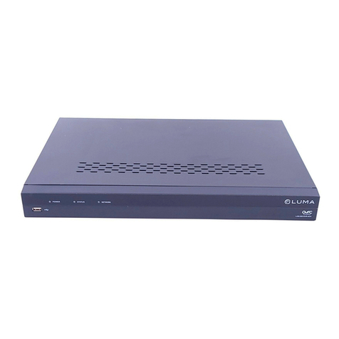
Delo DELOLUXcontrol User manual

User Manual
DELOLUXcontrol

4
Contents
Contents
1 General ........................................................................................................ 6
1.1 Information regarding these instructions ........................................................6
1.2 Company address and service.......................................................................6
1.3 Explanation of symbols ..................................................................................7
1.4 Limitation of liability ........................................................................................8
1.5 Copyright ........................................................................................................8
1.6 Spare parts .....................................................................................................9
1.7 Disposal ..........................................................................................................9
1.8 Warranty terms and liability ............................................................................9
1.9 CE conformity .................................................................................................9
2 Safety......................................................................................................... 10
2.1 Intended use.................................................................................................10
2.2 Contents of the instructions .........................................................................10
2.3 Modifications and alterations .......................................................................10
2.4 Responsibility of the operator.......................................................................11
2.5 Operating personnel .....................................................................................12
2.6 Personal protective equipment.....................................................................12
2.7 Specific risks ................................................................................................13
2.8 Labeling ........................................................................................................13
3 Technical data........................................................................................... 14
3.1 Display unit ...................................................................................................14
3.2 Detector head ...............................................................................................14
3.3 Sensor types.................................................................................................14
4 Design and function ................................................................................. 15
4.1 Device overview............................................................................................16
4.1.1 Display unit........................................................................................16
4.1.2 Interfaces...........................................................................................17
4.1.3 Detector head....................................................................................18

5
Contents
5 Shipping, packaging and storage........................................................... 20
5.1 Safety instructions for transport ...................................................................20
5.2 Receiving inspection.....................................................................................20
5.3 Identification and completeness...................................................................20
6 Installation and connection..................................................................... 21
6.1 Safety instructions ........................................................................................21
6.2 Installation and connection...........................................................................21
7 Operation .................................................................................................. 22
7.1 Safety instructions ........................................................................................22
7.2 Functions of DELOLUXcontrol......................................................................22
7.2.1 Overview of configuration options ....................................................22
7.2.2 Menu navigation ................................................................................24
7.2.3 Measuring without adapter ...............................................................25
7.2.4 Measuring with adapter.....................................................................26
7.2.5 Limiting value Emin ...........................................................................26
7.2.6 USB interface ....................................................................................26
8 Maintenance ............................................................................................. 27
8.1 Safety instructions ........................................................................................27
8.2 Maintenance plan .........................................................................................28
8.3 Repair ...........................................................................................................28
9 Malfunctions ............................................................................................. 29
9.1 Handling of malfunctions..............................................................................29
9.2 Possible error causes ...................................................................................29
10 Spare parts and accessories .................................................................. 30
11 Appendix ................................................................................................... 31
11.1 CE conformity ...............................................................................................31
11.2 Dimensions ...................................................................................................32
11.2.1 Dimensions of DELOLUXcontrol display unit....................................32
11.2.2 Dimensions of DELOLUXcontrol sensor ...........................................33
12 Index.......................................................................................................... 34

6
General
1 General
1.1 Information regarding these instructions
These operating instructions provide important information on how to work with the
device. Strict compliance with the safety instructions, and installing and operating
instructions is a prerequisite for safe and proper operation of the device.
Furthermore, the accident prevention regulations and general safety regulations applicable
at the place of use must also be complied with.
Read the instructions, especially chapter 2 Safety, page 10 et seq., and the respective
safety instructions, carefully before using the device. The operating instructions are a
product component and must be kept in the immediate vicinity of the device and
accessible to personnel at all times. The reader must understand what he or she has read.
Should there be any queries or questions, do not hesitate to contact the manufacturer at
any time.
This document is a translation of the original operating instructions.
Revision: R4.3 05/15
1.2 Company address and service
DELO Industrial Adhesives
DELO-Allee 1
86949 Windach
Germany
Phone +49 8193 9900-0
Fax +49 8193 9900-144
www.DELO.de

7
General
1.3 Explanation of symbols
Warnings
Warnings in these operating instructions are identified by symbols. These warnings are
introduced by signal words, which express the severity of a danger.
Comply with these warnings and act cautiously in order to avoid accidents, physical injury
and damage to property.
DANGER!
... indicates an imminently hazardous situation which, if not avoided, will
result in serious injury or death.
WARNING!
... indicates a potentially hazardous situation which, if not avoided, could
result in serious injury or death.
CAUTION!
... indicates a potentially hazardous situation which, if not avoided, may
result in minor or moderate injury.
ATTENTION!
... indicates a potentially hazardous situation which, if not avoided, may
result in property damage.
NOTE!
... emphasizes useful hints and recommendations as well as information
for efficient and trouble-free operation.

8
General
1.4 Limitation of liability
All information and notes in these operating instructions were compiled under due
consideration of valid standards and regulations, the present state of technology and
our years of knowledge and experience.
The manufacturer cannot be held liable for damage or injury resulting from:
Disregarding these operating instructions
Use in a manner not intended by the manufacturer
Use by untrained personnel
Disregarding error messages or malfunctions
Operation of faulty modules
Unauthorized alterations
Unauthorized modifications
Improper installation and connection
Disasters and force majeure
In case of customized versions, utilization of additional order options or due to recent
technical changes, the actual scope of supply can vary from the explanations and
illustrations in these instructions.
1.5 Copyright
The operating instructions are to be treated confidentially. They are intended only for
persons working with or on the device. Passing these operating instructions to third
parties without the written consent of the manufacturer is not permitted.
NOTE!
The reproduction, distribution and utilization of this document as well as
the communication of its contents to others without express authorization
is prohibited. Offenders will be held liable for the payment of damages. All
rights reserved in the event of the grant of a patent, utility model or
design.

9
General
1.6 Spare parts
WARNING!
Risk of injury from the use of incorrect spare parts!
Incorrect or defective spare parts can cause damage, malfunctions or
complete failure, and can impair safety.
Therefore:
Use only original parts by the manufacturer.
Order spare parts (see chapter 10 Spare parts and accessories, page 30) from
authorized dealers or directly from the manufacturer.
1.7 Disposal
If no return or disposal agreement has been made, recycle the device after proper
disassembly:
Scrap metal material
Dispose of electric components as electronic waste
The customer assumes the duty (§10 para. 2 ElektroG – Electrical and Electronic
Equipment Act) to dispose of the goods delivered in proper form according to the
statutory provisions at his own expense upon end of use (WEEE reg. no. DE 31546579).
Disposal by the manufacturer is possible on request.
1.8 Warranty terms and liability
Refer to the sales documents for the warranty terms.
The technical data relate to measurements at the point of time of goods issue within the
scope of general quality assurance. The values measured were determined under
laboratory conditions and may deviate depending on the conditions of use.
It is the user’s responsibility to test the suitability of the device for the intended purpose by
considering all specific requirements.
1.9 CE conformity
The declaration of conformity is provided in the appendix of these operating instructions
(see chapter 11.1 CE conformity, page 31).

10
Safety
2 Safety
This chapter gives an overview of all important safety aspects for protection of personnel
as well as safe and trouble-free operation.
2.1 Intended use
The device is exclusively conceived and designed for the use described herein.
NOTE!
DELOLUXcontrol, in combination with the corresponding detector heads,
serves to measure and control the intensity of the polymerization-effective
radiation of a curing lamp. The detector heads are subject to calibration.
Comply with the manufacturer’s instructions and operating instructions of
the lamps to be measured/controlled under any circumstances.
WARNING!
Danger from inappropriate use!
Any application beyond the scope of these operating instructions and/or
use other than intended can lead to dangerous situations.
Therefore:
Use the module for its intended purpose only.
Strictly follow all safety and handling instructions of the adhesives
used.
Strictly follow all safety instructions in chapter 6 Installation and
connection, page 21, chapter 7 Operation, page 22, and chapter 8
Maintenance, page 27.
2.2 Contents of the instructions
Every person, who works with or on the device, must read the operating instructions and
have understood them before working with or on the device. This also applies to persons
who have already worked with such a device or a similar one or who were trained by
the manufacturer.
2.3 Modifications and alterations
To avoid danger and ensure optimum performance, no modifications or changes may be
made to the device unless these have been expressly approved by the manufacturer.

11
Safety
2.4 Responsibility of the operator
The device is used commercially. The installer/operator is responsible for the safety of the
system in which the device is integrated. Therefore, the installer/operator of the device is
subject to statutory requirements for occupational safety.
Besides the instructions for occupational safety contained in these operating instructions,
operators must also follow general safety regulations, accident prevention regulations and
environmental protection regulations.
The following requirements apply in particular:
Read these operating instructions carefully and keep them for future consultation.
Pass on these operating instructions to any subsequent owner or user of the device.
The operator is responsible for staying informed of the applicable industrial safety
regulations and conducting a risk assessment to determine additional risks specific to
the area where the equipment is to be used. The operator company must address
these risks in the form of work instructions for the operation of the device.
These operating instructions must be kept in the immediate vicinity of the device and
accessible to the persons who work with or on the device at any time.
The directions in the operating instructions are to be followed completely and without
any changes!
The device may only be used if in technically sound and operational condition. If there
are doubts about the operability of the device or signs of fracture or other damage,
operation must be stopped immediately and the device must be sent to the
manufacturer for inspection and repair without delay.
The device must not be used unless the installing and operating procedure and
instructions have been read and understood by the persons using it.
The device must not be operated or connected other than in accordance with the type
plate and the operating instructions!
Comply with prescribed intervals or those specified in these operating instructions for
periodic checks and inspections.

12
Safety
2.5 Operating personnel
WARNING!
Risk of injury if personnel are not qualified!
Improper handling of the module can cause severe injuries and damage.
Therefore:
Special tasks must be performed only by the personnel designated in
the respective chapters of these instructions.
The operating instructions specify the following qualifications for various activity areas:
Trained personnel
have been instructed by the operator through training concerning the assigned tasks
and possible hazards in the event of improper use.
Skilled personnel
are personnel who, due to their specialized training, knowledge, and experience, as
well as knowledge of applicable regulations, are capable of executing the tasks
assigned to them, of recognizing possible hazards on their own and preventing them,
and are also capable of training other employees accordingly.
2.6 Personal protective equipment
When operating the device, personal protective equipment must be worn in order to
minimize the health risks.
Always wear the protective equipment required for the respective task during work.
Protective clothes
Close-fitting working clothes with a low tear strength, with snug sleeves
and no protruding parts. They predominantly serve to protect from
getting contact with chemicals and irradiation of bare skin by UV lamps.
Safety shoes
Protect against heavy falling objects and slipping on chemical residues.
Protective gloves
Protect the hands from rubbing, abrasions, incisions or more serious
injuries when touching hot surfaces and from UV light when working
under curing lamps.
Safety glasses
Protect the eyes from flying parts and splashes. Furthermore, they
protect the eyes from direct or indirect radiation by UV lamps.

13
Safety
2.7 Specific risks
This chapter describes the residual risks resulting from the risk assessment.
The safety instructions and warnings described here and in further chapters of these
operating instructions must be followed to reduce health risks and prevent dangerous
situations.
WARNING!
Risk of injury when the detector head heats up!
The radiation sensor and the metal attachment components may strongly
heat up during measuring and can cause severe burns when directly
touched.
Therefore:
Always wear protective gloves and safety glasses when working with
light sources.
Do not leave the detector head in the ray path longer than is necessary
2.8 Labeling
The following symbols and labels are present in the work area. They apply to the direct
surroundings of their location.
WARNING!
Risk of injury due to illegible symbols!
In the course of time, labels and symbols can get dirty or become illegible
for other reasons.
Therefore:
Always keep all safety, warning and operating information at the
module legible.
Labels must be replaced immediately if they get lost.
Read the operating instructions
Use the labeled object only after reading the operating instructions.

14
Technical data
3 Technical data
Note: Detailed dimensions are found in the dimension drawing in the appendix,
chapter 11.2 Dimensions, page 32.
3.1 Display unit
Dimensions L x W x H approx. 145 x 63 x 31 mm
Weight 161 g
Display range 0.1 – 99,999 mW/cm²
Resolution of the UV irradiance 0.1 mW/cm²
Operating temperature +5 °C to +40 °C
Voltage supply 2 x mignon AA 1.5 V
Interface USB
3.2 Detector head
Dimensions dia. 37 x 8 mm
Weight 100 g
Diameter of the detection area 9 mm (UVA, BLUE, LED 9 mm)
1 mm (LED 1 mm)
Operating temperature +5 °C to +100 °C
Calibration irradiance in mW/cm² with
factory calibration report
Connection line light guide, length: 1.3 m
minimum bending radius: 100 mm
Irradiation time interval / no permanent irradiation
3.3 Sensor types
Sensor Wavelength range
UVA sensor 315 – 395 nm*
BLUE sensor 390 – 480 nm*
9 mm LED sensor 365 / 400 / 460 nm
1 mm LED sensor 365 / 400 / 460 nm
* The calibration standard is a Hg bulb. The reference basis is the spectrum of DELOLUX 03 S and DELOLUX 04

15
Design and function
4 Design and function
DELOLUXcontrol, in combination with the corresponding detector heads, serves to
measure and control the intensity of the polymerization-effective radiation of a curing
lamp. The detector heads are subject to calibration. Comply with the manufacturer’s
instructions and operating instructions of the lamps to be measured/controlled under
any circumstances.
In combination with different detector heads, the intensity at the required working position
can be measured. Alternatively, the intensity at the light guide outlet or the lamp head can
be detected. In order to measure the intensity directly at the light guide outlet or the lamp
head of a DELOLUX lamp, an adapter (aperture) must be screwed on / attached for
centering.
Application areas:
Sensor Wavelength range in combination with
UVA sensor 315 – 395 nm* DELOLUX 03 S
DELOLUX 04 (with adapter if required)
DELOLUX 06
BLUE sensor 390 – 480 nm* DELOLUX 03 S
DELOLUX 04 (with adapter if required)
DELOLUX 06
9 mm LED sensor 365 / 400 / 460 nm DELOLUX 20
DELOLUX 202
DELOLUX 22
DELOLUX 80 (with adapter if required)
1 mm LED sensor 365 / 400 / 460 nm DELOLUX 50 (with adapter if required)
* The calibration standard is a Hg bulb. The reference basis is the spectrum of DELOLUX 03 S and DELOLUX 04

16
Design and function
4.1 Device overview
4.1.1 Display unit
1
2
Pos. Control element /
component
Remark
1LCD display The display indicates the currently measured value in
mW/cm². (Exception: Display UL/OL = measuring
value to high resp. too low)
In addition, the display shows the serial number of
the selected detector head, the selected adapter
(aperture reduction of the measuring area) if
applicable, or the specific wavelength (LED
detector heads).
2Control panel Panel for startup of DELOLUX control, menu
navigation, display background lighting, measuring
value hold function, switching off.

17
Design and function
4.1.2 Interfaces
1
2
Pos. Control element /
component
Remark
1USB port Data exchange with a superior control unit
(PLC or PC)
2Connector for detector
head
Connection socket for a detector head assigned to
the light intensity meter

18
Design and function
4.1.3 Detector head
1
2
3
4
5

19
Design and function
Pos. Control element /
component
Remark
1Radiation sensor With the radiation sensor, the high-intensity radiation
(UVA, BLUE or LED) is absorbed and carried to the
actual detector (4). The measuring intervals must be
kept short to prevent aging of the sensor.
2Adapter If it is not the intensity value at the actual irradiation
area that is to be determined, but rather the curing
lamp itself is to be checked, it is recommended that
the respective adapter (aperture/Apt) is used. The
adapters center the light guide over the sensor,
while parts of the sensor are covered. It is essential
to select the adapter that reduces the sensor area
(3, 5, 5 mm adapters) in the parameter set of the
display unit. Otherwise, the radiation intensity is
determined on the basis of the 9 mm area of the
sensor, which results in faulty measuring or
misinterpretation.
3Light guide The optical radiation is carried to the detector via
the light guide. Protect the light guide against
mechanical damage/impair. The minimum bending
radius is 100 mm.
4Detector The radiation detector converts the radiation into
an electrical signal. This signal is forwarded to the
display via the signal line. The detector is spatially
separated from the sensor as temperature
fluctuations at the detector may falsify the
measuring signal.
5Signal line with plug The detector head is connected to the display unit
by means of the plug. The signal line is made of a
high-quality, fail-safe coaxial cable.

20
Shipping, packaging and storage
5 Shipping, packaging and storage
5.1 Safety instructions for transport
Unauthorized transport
ATTENTION!
Damage from unauthorized transport!
Transport or shipping by untrained personnel can damage the device.
Therefore:
Transport internally or return for repair and maintenance only in the
original packaging (hard top case).
Shocks should be prevented.
Never let the device fall down onto the floor or the work bench.
DELO cannot be held liable for damage resulting from
defective packaging.
Do not bend the metal sheathing of the detector head line (minimum
bending radius 100 mm).
Do not subject the signal line to torsional or tensile stress.
Storage
The device must be stored in a cool and dry place.
5.2 Receiving inspection
Check the shipment for completeness and shipping damage immediately upon receipt. If
any external shipping damage is visible, proceed as follows:
Accept the shipment only conditionally or not at all.
Note down the extent of damage on the transport documents or the delivery note of
the forwarding agent.
File a complaint.
5.3 Identification and completeness
The device is identified by the designation and order number on the type plate.
Depending on the ordered combination, the complete product as delivered includes:
One hard top case
One DELOLUXcontrol display unit
One USB connection cable
One socket wrench with 3 counter sunk screws M3x6 (not included in the package of
the 9 mm LED sensor)
Operating instructions
One CD-ROM (LabVIEW example software, DLL USB file, operating instructions)
Depending on the equipment: One or several detector heads, the corresponding
adapters and the factory calibration report

21
Installation and connection
6 Installation and connection
6.1 Safety instructions
CAUTION!
Damage or faulty measuring results through improper installation
and connection!
Therefore:
Do not position the detector head in such a way that it is permanently
in the ray path.
Do not bend the metal sheathing of the detector head line (minimum
bending radius 100 mm).
Do not subject the signal line to torsional or tensile stress.
Pay attention to the permissible ambient temperatures.
Prevent radiation from other light sources and solar radiation.
Protect the device from humidity.
Follow the safety instructions and operating instruction of the
irradiation equipment used.
Pay attention to the specific allocation of detector to DELOLUXcontrol.
Personal protective equipment
Wear protective clothing when operating the module:
Protective clothes
Safety glasses
Protective gloves
6.2 Installation and connection
DELOLUXcontrol is designed for mobile use.
NOTE!
Store the light intensity meter in the supplied hard top case for optimal
protection.
Only the detector heads assigned to DELOLUXcontrol can be used as the calibration data
of the detector heads are saved in the calibration data memory of the light intensity meter.
The detector heads are assigned via the corresponding serial numbers that are found on
the back of the device, on the cylindric part of the sensor, as well as in the supplied
factory calibration report.
Start of operation
Attach the detector head to the miniature SUB-D. Secure the plug against unintended
unplugging by means of the locking screws. Switch on the device and select the sensor,
the adapter if applicable and/or the wavelength (see chapter 7 Operation, page 22). The
device is switched off by pressing the menu / enter key over a certain period of time
(approx. 2 s).

22
Operation
7 Operation
7.1 Safety instructions
CAUTION!
Damage or faulty measuring results through improper operation!
Improper operation can cause damage.
Therefore:
The selection of the sensor from the parameter set of the display unit
must correspond to the serial number of the detector of the detector
head connected under any circumstances.
The sensor must not be damaged or contaminated.
Protect the detector against temperature fluctuations during
measuring. Make sure that the temperature is constant according
to the specification.
Personal protective equipment
Wear protective clothing when operating the module:
Protective clothes
Safety glasses
Protective gloves
7.2 Functions of DELOLUXcontrol
7.2.1 Overview of configuration options
The manufacturer programs DELOLUXcontrol in such a way that only the detector heads
supplied can be selected. If another detector head is to be included, the display unit
must be sent to the manufacturer so that the respective detector head can be activated
and the calibration factor can be entered. An arbitrary combination of sensors and display
units is not possible due to the permanently stored calibration values.
The following menu selection results from the maximum equipment (4 detector heads):
Table of contents
Popular Measuring Instrument manuals by other brands

Maxwell
Maxwell AutoAnchor 730 owner's manual

Unilevel
Unilevel UNG6001 instruction manual

HSS Hire
HSS Hire 49420 Operating & safety guide
Ocean Optics
Ocean Optics NIR Series Installation and operation manual
Kobold
Kobold KAL-E EX Series operating instructions
PCE Health and Fitness
PCE Health and Fitness PCE-RVI 6 user manual
