Otto Bock 6A40 User manual

Gebrauchsanweisung ............................. 5
Instructions for use ................................. 11
Instructions d'utilisation........................... 18
Istruzioni per l’uso .................................. 25
Instrucciones de uso............................... 31
Manual de utilização................................ 38
Gebruiksaanwijzing................................. 45
Bruksanvisning....................................... 52
Brugsanvisning ...................................... 58
Bruksanvisning....................................... 64
Käyttöohje.............................................. 71
Instrukcja użytkowania............................. 77
Használati utasítás .................................. 84
Návod k použití....................................... 90
Instrucţiuni de utilizare............................. 96
Upute za uporabu ................................... 103
Navodila za uporabo ............................... 109
Návod na používanie ............................... 115
Инструкция за употреба......................... 122
Kullanma talimatı .................................... 129
Οδηγίες χρήσης ..................................... 135
Руководство по применению .................. 143
取扱説明書............................................. 150
使用说明书............................................. 156
사용 설명서............................................ 162
6A40 MagnoFlex Lock, 6A43

1 2
345
2

678
9 10 11
3

12 13 14
15 16
4

1 Produktbeschreibung Deutsch
INFORMATION
Datum der letzten Aktualisierung: 2020-11-05
►Lesen Sie dieses Dokument vor Gebrauch des Produkts auf
merksam durch und beachten Sie die Sicherheitshinweise.
►Weisen Sie den Benutzer in den sicheren Gebrauch des Pro
dukts ein.
►Wenden Sie sich an den Hersteller, wenn Sie Fragen zum Pro
dukt haben oder Probleme auftreten.
►Melden Sie jedes schwerwiegende Vorkommnis im Zusammen
hang mit dem Produkt, insbesondere eine Verschlechterung des
Gesundheitszustands, dem Hersteller und der zuständigen Be
hörde Ihres Landes.
►Bewahren Sie dieses Dokument auf.
1.1 Konstruktion und Funktion
Das MagnoFlex Lock 6A40 ist ein Shuttle Lock mit einem flexiblen Pin
und einem in das Gehäuse integrierten Magneten. Es dient zur Fixie
rung eines geeigneten Liners im Prothesenschaft. Die Montage des
Shuttle Locks erfolgt im Testschaft durch Tiefziehen und im Definitiv
schaft durch Einlaminieren. Zur Verbindung mit den distalen Prothe
senkomponenten ist es mit einem Vierlochanschluss ausgestattet. Der
flexible Pin wird am Liner montiert. Beim Einsteigen in den Prothesen
schaft richtet der Magnet im MagnoFlex Lock den flexiblen Pin zur
Öffnung hin aus. Dies erleichtert den Einstieg in die Prothese.
1.2 Kombinationsmöglichkeiten
Diese Prothesenkomponente ist kompatibel mit dem Ottobock Modu
larsystem. Die Funktionalität mit Komponenten anderer Hersteller, die
über kompatible modulare Verbindungselemente verfügen, wurde
nicht getestet.
Kombinationseinschränkungen für Ottobock Komponenten
Benennung Kennzeichen
Schaftadapter 4R54, 4R77
Verschiebeplatte
(Die Distanzplatte 4X314 wird zusätzlich benö
tigt.)
6A41
2 Bestimmungsgemäße Verwendung
2.1 Verwendungszweck
Das Produkt ist ausschließlich für die exoprothetische Versorgung der
unteren Extremität einzusetzen.
2.2 Einsatzgebiet
• Das maximal zugelassene Körpergewicht ist in den Technischen
Daten angegeben (siehe Seite11).
2.3 Umgebungsbedingungen
Zulässige Umgebungsbedingungen
Einsatztemperaturbereich -10 °C bis +60°C
Zulässige relative Luftfeuchtigkeit 0 % bis 90 %, nicht kondensie
rend
Unzulässige Umgebungsbedingungen
Mechanische Vibrationen oder Stöße
Schweiß, Urin, Süßwasser, Salzwasser, Säuren
Staub, Sand, stark hygroskopische Partikel (z.B. Talkum)
2.4 Nutzungsdauer
Das Produkt wurde vom Hersteller mit 3 Millionen Belastungszyklen
geprüft. Dies entspricht, je nach Aktivitätsgrad des Benutzers, einer
Nutzungsdauer von maximal 5Jahren.
5

3 Sicherheit
3.1 Bedeutung der Warnsymbolik
VORSICHT Warnung vor möglichen Unfall- und Verletzungsge
fahren.
3.2 Allgemeine Sicherheitshinweise
VORSICHT
Überbeanspruchung des Produkts
Verletzungsgefahr durch Bruch tragender Teile
►Setzen Sie die Prothesenkomponenten gemäß der MOBIS-Klas
sifizierung ein.
VORSICHT
Unzulässige Kombination von Prothesenkomponenten
Verletzungsgefahr durch Bruch oder Verformung des Produkts
►Kombinieren Sie das Produkt nur mit Prothesenkomponenten,
die dafür zugelassen sind.
►Prüfen Sie anhand der Gebrauchsanweisungen der Prothesen
komponenten, ob sie auch untereinander kombiniert werden dür
fen.
VORSICHT
Überschreitung der Nutzungsdauer und Wiederverwendung an
einem anderen Patienten
Verletzungsgefahr durch Funktionsverlust sowie Beschädigungen
am Produkt
►Sorgen Sie dafür, dass die geprüfte Nutzungsdauer nicht über
schritten wird.
►Verwenden Sie das Produkt nur für einen Patienten.
6
VORSICHT
Verwendung unter unzulässigen Umgebungsbedingungen
Verletzungsgefahr durch Schäden am Produkt
►Setzen Sie das Produkt keinen unzulässigen Umgebungsbedin
gungen aus.
►Wenn das Produkt unzulässigen Umgebungsbedingungen aus
gesetzt war, prüfen Sie es auf Schäden.
►Verwenden Sie das Produkt bei offensichtlichen Schäden oder
im Zweifelsfall nicht weiter.
►Sorgen Sie im Bedarfsfall für geeignete Maßnahmen (z.B. Reini
gung, Reparatur, Ersatz, Kontrolle durch den Hersteller oder ei
ne Fachwerkstatt, etc.).
VORSICHT
Mechanische Beschädigung des Produkts
Verletzungsgefahr durch Funktionsveränderung oder -verlust
►Arbeiten Sie sorgfältig mit dem Produkt.
►Prüfen Sie ein beschädigtes Produkt auf Funktion und Ge
brauchsfähigkeit.
►Verwenden Sie das Produkt bei Funktionsveränderungen oder -
verlust nicht weiter (siehe „Anzeichen von Funktionsveränderun
gen oder -verlust beim Gebrauch“ in diesem Kapitel).
►Sorgen Sie im Bedarfsfall für geeignete Maßnahmen (z.B. Re
paratur, Austausch, Kontrolle durch den Kunden-Service des
Herstellers, etc.).
VORSICHT
Produkt enthält einen Magneten
Beeinflussung oder Beschädigung von Geräten und Gegenständen
durch starkes Magnetfeld
►Halten Sie das Produkt von Geräten und Gegenständen fern, die
auf Magnetfelder empfindlich reagieren.

Anzeichen von Funktionsveränderungen oder -verlust beim Ge
brauch
Funktionsveränderungen können sich z.B. durch ein verändertes
Gangbild, eine veränderte Positionierung der Prothesenkomponenten
zueinander sowie durch Geräuschentwicklung bemerkbar machen.
4 Lieferumfang
6A40
Ab
b.
Po
s.
Men
ge
Benennung Kennzeichen
– – 1 Gebrauchsanweisung 647G931
1 1 1 MagnoFlex Lock –
1 Gewindestift (für Rastein
heit)
506G3=M3X5-
„Niro“
1 2 1 Eingussadapter 6A43
1 3 1 Flexibler Pin 6Y13=F1
1 4 1 Schraube 503S3
1 5 1 Tiefziehdummy –
1 6 4 Einschlagbuchse –
1 7 4 Zylinderkopfschraube 501T28=M6X8
1 8 4 Senkschraube 501S41=M6X45
1 8 4 Senkschraube 501S41=M6X50
1 9 1 Rasteinheit 5A52=K
6A43
Menge Benennung Kennzeichen
1 Eingussadapter 6A43
1 Schraube 503S3
1 Tiefziehdummy –
4 Einschlagbuchse –
4 Zylinderkopfschraube 501T28=M6X8
7
5 Gebrauchsfähigkeit herstellen
VORSICHT
Fehlerhafter Aufbau oder Montage
Verletzungsgefahr durch Schäden an Prothesenkomponenten
►Beachten Sie die Aufbau- und Montagehinweise.
INFORMATION
►Möglicherweise sind nicht alle Materialien in Ihrem Land erhält
lich. Nehmen Sie in diesem Fall Kontakt zur lokalen Niederlas
sung des Herstellers auf, um Informationen zu alternativen Mate
rialien zu erhalten.
5.1 Prothesenschaft herstellen
INFORMATION
Die in diesem Dokument beschriebene Armierung wurde für das
maximale Körpergewicht des Anwenders des Produkts freigegeben.
Jede Veränderung der Armierung liegt in der Verantwortung des Or
thopädietechnikers.
5.1.1 Schaftherstellung vorbereiten
>Benötigte Werkzeuge und Materialien:
Eingussadapter 6A43, Zylinderschrauben 501T28=M6X8, Tief
ziehdummy, Schraube 503S3, Wachs 633W8, Plastaband
636K8=*
1) Die Zylinderschrauben (Gewinde und Kopf von außen) mit Wachs
isolieren.
2) Die Zylinderschrauben in den Eingussadapter einschrauben
(siehe Abb.2).
3) Den Kopf der Zylinderschrauben mit Plastaband füllen (siehe
Abb.3).
4) Den Eingussadapter in der Längsachse des Stumpfs auf dem
Gipspositiv platzieren.

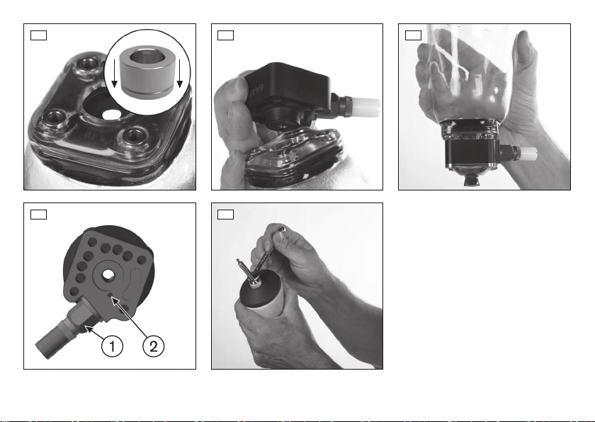
5) Den Tiefziehdummy in die runde Öffnung des Eingussadapters le
gen und beide mit der Senkschraube am Gipspositiv fixieren
(siehe Abb.4).
6) Den Kopf der Senkschraube mit Plastaband isolieren.
7) Wenn ein Hinterschnitt zwischen Eingussadapter und Gips
positiv vorhanden ist: Den Hinterschnitt mit Gipsbrei auffüllen.
5.1.2 Herstellen eines Testschafts
>Benötigte Werkzeuge und Materialien:
Spannrahmen 755T4=360, Vakuumrohr 755X104=360 (mit Vaku
umdichtscheibe), Vakuumpumpe 755E9, Oszillierende Säge
756D2, 756B12=* oder 756B20=*, ThermoLyn steif 616T52=*
oder ThermoLyn clear 616T83=*, Bindfaden
1) Die Herstellung des Prothesenschafts vorbereiten (siehe Seite7).
2) Zwei Bindfäden über kreuz auf dem Eingussadapter platzieren
(siehe Abb.5). Die Bindfäden bilden Luftkanäle, die das Anfor
men des Tiefziehmaterials an die Konturen erleichtern.
3) Den Tiefziehvorgang mit ThermoLyn durchführen.
4) Den Prothesenschaft nacharbeiten (siehe Seite9).
5.1.3 Unterschenkelschaft laminieren
>Benötigte Werkzeuge und Materialien:
PVA-Folienschlauch 99B81=70X19X5 und 99B81=100X19X5,
Perlon-Trikotschlauch 623T3=8 oder 623T3=10, Schlauchstrumpf
81A1=8 oder 81A1=10, Carbonfaser-Gewebeband 616B1=25x*,
Carbon-UD-Schlauch 616G2, Carbonfaser-Flechtschlauch
616G15, Orthocryl-Laminierharz 80:20 PRO 617H119, Bindfaden
1) Die Herstellung des Prothesenschafts vorbereiten (siehe Seite7).
2) Den kürzeren PVA-Folienschlauch einweichen und über das
Gipspositiv ziehen.
3) Einen Schlauchstrumpf über das Gipspositiv ziehen.
4) Eine Lage Carbonfaser-Gewebeband zirkulär um den MPT-Punkt
(Mitte Patella Tendum) platzieren (siehe Abb.6).
5) Medial und lateral eine Lage Carbonfaser-Gewebeband vom
Shuttle Lock bis zu den Kondylen platzieren (siehe Abb.7).
8
6) Anterior und posterior eine Lage Carbonfaser-Gewebeband vom
Shuttle Lock bis zum zirkulären Carbonfaser-Gewebeband plat
zieren (siehe Abb.8).
7) Einen Schlauchstrumpf über das Gipspositiv ziehen.
8) Einen Bindfaden zirkulär in die Rille des Eingussadapters einle
gen und stramm abbinden (##03119).
9) Ein Stück Carbon-UD-Schlauch zuschneiden (1,5-fache Länge
des Gipspositivs).
10) Den Carbon-UD-Schlauch bis zum Schaftrand über das Gipspo
sitiv ziehen. Den oberen Teil des Carbon-UD-Schlauch abbinden
und die restliche Länge über das Gipspositiv umschlagen.
11) Einen Bindfaden zirkulär in die Rille des Eingussadapters einle
gen und stramm abbinden (siehe Abb.9).
12) Einen Schlauchstrumpf über das Gipspositiv ziehen.
13) Ein Stück Carbonfaser-Flechtschlauch zuschneiden (1,3-fache
Länge des Gipspositivs).
14) Den Carbonfaser-Flechtschlauch bis zum Schaftrand über das
Gipspositiv ziehen. Den oberen Teil des Carbonfaser-Flechts
chlauchs abbinden und die restliche Länge über das Gipspositiv
umschlagen (siehe Abb.10).
15) Ein Stück Perlon-Trikotschlauch zuschneiden (2-fache Länge des
Gipspositivs).
16) Den Perlon-Trikotschlauch bis zum Schaftrand über das Gipspo
sitiv ziehen. Den oberen Teil des Perlon-Trikotschlauch abbinden
und die restliche Länge über das Gipspositiv umschlagen.
17) Den längeren PVA-Folienschlauch einweichen und über das
Gipspositiv ziehen.
18) Den Gießvorgang mit Orthocryl durchführen.
19) Den Prothesenschaft nacharbeiten (siehe Seite9).

5.1.4 Oberschenkelschaft laminieren
>Benötigte Werkzeuge und Materialien:
PVA-Folienschlauch 99B81=100X26X5 und 99B81=130X26X5,
Perlon-Trikotschlauch 623T3=12 oder 623T3=15, Schlauch
strumpf 81A1=12 oder 81A1=15, Carbonfaser-Gewebeband
616B1=50x*, Carbon-UD-Schlauch 616G2, Carbonfaser-Flecht
schlauch 616G15, Orthocryl-Laminierharz 80:20 PRO 617H119,
Bindfaden
1) Die Herstellung des Prothesenschafts vorbereiten (siehe Seite7).
2) Den kürzeren PVA-Folienschlauch einweichen und über das
Gipspositiv ziehen.
3) Eine Lage Perlon-Trikotschlauch über das Gipspositiv ziehen.
4) Eine Lage Carbonfaser-Gewebeband zirkulär 3cm unterhalb des
Perineums platzieren.
5) Je eine Lage Carbonfaser-Gewebeband medial und lateral sowie
anterior und posterior vom Shuttle Lock bis zum zirkulären Car
bonfaser-Gewebeband platzieren.
6) Eine Lage Carbonfaser-Gewebeband zirkulär 3cm unterhalb des
Perineums platzieren.
7) Zwei Carbonfaser-Gewebebänder abschneiden (Länge ca.
20cm).
8) Die Carbonfaser-Gewebebänder durch Umklappen in der Mitte
zu einem V formen und im Bereich der Tuber-Anstützung platzie
ren.
9) Einen Schlauchstrumpf über das Gipspositiv ziehen.
10) Einen Bindfaden zirkulär in die Rille des Eingussadapters einle
gen und stramm abbinden.
11) Ein Stück Carbon-UD-Schlauch zuschneiden (1,5-fache Länge
des Gipspositivs).
12) Den Carbon-UD-Schlauch bis zum Schaftrand über das Gipspo
sitiv ziehen. Den oberen Teil des Carbon-UD-Schlauch abbinden
und die restliche Länge über das Gipspositiv umschlagen.
13) Einen Bindfaden zirkulär in die Rille des Eingussadapters einle
gen und stramm abbinden.
9
14) Einen Schlauchstrumpf über das Gipspositiv ziehen.
15) Ein Stück Carbonfaser-Flechtschlauch zuschneiden (1,3-fache
Länge des Gipspositivs).
16) Den Carbonfaser-Flechtschlauch bis zum Schaftrand über das
Gipspositiv ziehen. Den oberen Teil des Carbonfaser-Flechts
chlauchs abbinden und die restliche Länge über das Gipspositiv
umschlagen.
17) Ein Stück Perlon-Trikotschlauch zuschneiden (2-fache Länge des
Gipspositivs).
18) Den Perlon-Trikotschlauch bis zum Schaftrand über das Gipspo
sitiv ziehen. Den oberen Teil des Perlon-Trikotschlauch abbinden
und die restliche Länge über das Gipspositiv umschlagen.
19) Den längeren PVA-Folienschlauch einweichen und über das
Gipspositiv ziehen.
20) Den Gießvorgang mit Orthocryl durchführen.
21) Den Prothesenschaft nacharbeiten (siehe Seite9).
5.1.5 Nacharbeiten des Prothesenschafts
>Benötigte Materialien:
Einschlagbuchsen
1) Die Kontur des Prothesenschafts anzeichnen und beschneiden.
2) Das distale Schaftende bis auf den Tiefziehdummy und die Köpfe
der Zylinderschrauben abschleifen (siehe Abb.11).
3) Auf einer ebenen Fläche überprüfen, ob die beschliffene Fläche
plan ist. Wenn notwendig nachbessern.
4) Den Tiefziehdummy und die Zylinderschrauben von Prothesen
schaft entfernen.
5) Den Prothesenschaft vom Gipspositiv entfernen.
6) Die Kontur des Prothesenschafts beschleifen.
7) Die Einschlagbuchsen in die Öffnungen einsetzen, aus denen die
Zylinderschrauben entfernt wurden (siehe Abb.12).

5.2 Montieren des Shuttle Locks und des Schaftadapters
VORSICHT
Verwenden von flüssiger Schraubensicherung
Verletzungsgefahr durch Ausreißen von Schraubverbindungen
►Verwenden Sie keine flüssige Schraubensicherung (z.B.
Loctite®). Die Schraubensicherung beschädigt das Kunststoff
material.
INFORMATION
Das Produkt enthält einen Magneten
►Halten Sie zu einem Herzschrittmacher mindestens 12cm Si
cherheitsabstand ein.
>Benötigte Werkzeuge und Materialien:
Schaftadapter, Senkschrauben 501S41=M6X45, Gewindestift
506G3=M3X5-„Niro“, Drehmomentschlüssel 710D4, Drehmo
mentschlüssel (auf 0,5Nm einstellbar)
1) Das Shuttle Lock so ausrichten, dass der Magnet proximal und
die Rasteinheit medial oder lateral ausgerichtet ist.
2) Das Shuttle Lock auf den Prothesenschaft aufsetzen (siehe
Abb.13).
3) Optional: Die Distanzplatte 4X314 und anschließend die Ver
schiebeplatte 6A41 auf dem Shuttle Lock platzieren.
4) Den ausgewählten Schaftadapter auf dem Shuttle Lock platzie
ren.
5) Die Senkschrauben für den Schaftadapter auswählen:
Für 4R54: 501S41=M6x45
Für 4R77: 501S41=M6x50
6) Die Senkschrauben durch den Schaftadapter und das Shuttle
Lock in den Eingussadapter einstecken und anziehen (siehe
Abb.14) (Montage-Anzugsmoment: 12Nm).
7) Die Rasteinheit (siehe Abb.15, Pos. 1) in das Shuttle Lock ein
drehen und mit Drehmomentschlüssel festdrehen (Montage-An
zugsmoment: 10Nm).
10
8) Die Rasteinheit mit dem Gewindestift (siehe Abb.15, Pos. 2) si
chern (Montage-Anzugsmoment: 0,5Nm).
5.3 Montieren des Pins
VORSICHT
Montage des Pins an einem nicht zugelassenen Liner
Verletzungsgefahr durch Lösen der Schraubverbindung
►Montieren Sie den Pin nur an Linern mit Metallgewinde unter Be
achtung des angegebenen Anzugsmoments.
Der Pin zur Verbindung des Liners mit dem Shuttle Lock, wird in das
Gewinde am distalen Ende des Liners eingeschraubt.
>Benötigte Werkzeuge und Materialien:
Drehmomentschlüssel (auf 3Nm einstellbar), Loctite® 636K13
1) Loctite® auf das Gewinde auftragen.
2) HINWEIS! Den Pin nicht kürzen.
Den Pin in das Gewinde einschrauben und anziehen (siehe
Abb.16) (Montage-Anzugsmoment: 3Nm).
6 Gebrauch
VORSICHT
Pin wird nicht vollständig in das Lock eingeführt
Verletzungsgefahr durch Verlust der Verbindung zur Prothese
►Führen Sie den Pin gemäß den Handlungsanweisungen in das
Lock ein.
►Prüfen Sie vor jedem Gebrauch der Prothese, ob der Pin im
Lock arretiert ist.
Der Liner und das Shuttle Lock werden über den Pin miteinander ver
bunden. Der Pin rastet im Shuttle Lock ein und hält den Liner fest.
Anziehen des Liners
1) Den Pin und den Liner auf Schäden überprüfen. Der Pin muss
flexibel sein und immer in die Ausgangsstellung zurückfedern.

2) HINWEIS! Eine falsche Ausrichtung des Pins führt zur Be
schädigung beim Einführen in das Shuttle Lock.
Den Liner so am Stumpfende ansetzen, dass der Pin in Stumpf
längsachse ausgerichtet ist.
3) Den Liner auf den Stumpf abrollen.
4) Den Sitz des Liners und die Ausrichtung des Pins überprüfen.
Einsteigen in den Prothesenschaft
1) Mit dem Liner in den Prothesenschaft einsteigen, bis der Pin in
die Öffnung des Eingussadapters gleitet.
2) INFORMATION: Während des Einführens des Pins entstehen
klickende Geräusche, die durch den Magneten hervorgeru
fen werden. Diese Geräusche geben keinen Aufschluss dar
über, ob der Pin in der Rasteinheit arretiert ist.
Den Pin vollständig in das Shuttle Lock stecken.
3) Vor dem Gebrauch der Prothese prüfen, ob der Pin im Shuttle
Lock arretiert ist.
Aussteigen aus dem Prothesenschaft
►Den seitlichen Taster gedrückt halten und den Stumpf mit Liner
aus dem Prothesenschaft ziehen.
7 Wartung
►Die Prothesenkomponenten nach den ersten 30Tagen Gebrauch
einer Sichtprüfung und Funktionsprüfung unterziehen.
►Die komplette Prothese während der normalen Konsultation auf
Abnutzung überprüfen.
►Jährliche Sicherheitskontrollen durchführen.
8 Rechtliche Hinweise
Alle rechtlichen Bedingungen unterliegen dem jeweiligen Landesrecht
des Verwenderlandes und können dementsprechend variieren.
8.1 Haftung
Der Hersteller haftet, wenn das Produkt gemäß den Beschreibungen
und Anweisungen in diesem Dokument verwendet wird. Für Schäden,
die durch Nichtbeachtung dieses Dokuments, insbesondere durch
11
unsachgemäße Verwendung oder unerlaubte Veränderung des Pro
dukts verursacht werden, haftet der Hersteller nicht.
8.2 CE-Konformität
Das Produkt erfüllt die Anforderungen der Verordnung (EU) 2017/745
über Medizinprodukte. Die CE-Konformitätserklärung kann auf der
Website des Herstellers heruntergeladen werden.
9 Technische Daten
Kennzeichen 6A40
Gewicht [g] 225
Systemhöhe [mm] 37
Material Hochleistungspolyamid und Me
tall
Max. Körpergewicht [kg] 125
1 Product description English
INFORMATION
Date of last update: 2020-11-05
►Please read this document carefully before using the product
and observe the safety notices.
►Instruct the user in the safe use of the product.
►Please contact the manufacturer if you have questions about the
product or in case of problems.
►Report each serious incident related to the product to the manu
facturer and to the relevant authority in your country. This is par
ticularly important when there is a decline in the health state.
►Please keep this document for your records.
1.1 Construction and Function
The 6A40 MagnoFlex Lock is a shuttle lock with a flexible pin and a
magnet integrated in the housing. It serves to secure a suitable liner in
the prosthetic socket. The shuttle lock is installed in the check socket

by vacuum forming and in the definitive socket by lamination. To con
nect to the distal prosthetic components, it is equipped with a four-
hole connector. The flexible pin is installed on the liner. When sliding
into the prosthetic socket, the magnet in the MagnoFlex Lock aligns
the flexible pin with the opening. This makes it easier to don the pros
thesis.
1.2 Combination possibilities
This prosthetic component is compatible with Ottobock's system of
modular connectors. Functionality with components of other manufac
turers that have compatible modular connectors has not been tested.
Limited combination options for Ottobock components
Designation Reference num
ber
Socket adapter 4R54, 4R77
Slide plate
(The 4X314 spacer plate is required in addi
tion.)
6A41
2 Intended use
2.1 Indications for use
The product is intended exclusively for lower limb exoprosthetic fit
tings.
2.2 Area of application
• The maximum approved body weight is specified in the technical
data (see page18).
2.3 Environmental conditions
Allowable environmental conditions
Temperature range for use: -10°Cto +60°C
Allowable relative humidity 0% to 90%, non-condensing
Unallowable environmental conditions
Mechanical vibrations or impacts
12
Unallowable environmental conditions
Perspiration, urine, fresh water, salt water, acids
Dust, sand, highly hygroscopic particles (e.g. talcum)
2.4 Service life
This product was tested by the manufacturer with 3million load
cycles. Depending on the user’s activity level, this corresponds to a
maximum service life of 5years.
3 Safety
3.1 Explanation of warning symbols
CAUTION Warning regarding possible risks of accident or
injury.
3.2 General safety instructions
CAUTION
Excessive strain on the product
Risk of injury due to breakage of load-bearing components
►Use the prosthetic components according to the MOBIS classi
fication.
CAUTION
Improper combination of prosthetic components
Risk of injury due to breakage or deformation of the product
►Only combine the product with prosthetic components that are
approved for that purpose.
►Based on the instructions for use of the prosthetic components,
verify that they may be combined with each other.
CAUTION
Exceeding the service life and reuse on another patient
Risk of injury due to loss of functionality as well as damage to the
product

►Ensure that the approved service life is not exceeded.
►Only use the product on a single patient.
CAUTION
Use under restricted environmental conditions
Risk of injury due to damage to the product
►Do not expose the product to restricted environmental condi
tions.
►If the product has been exposed to restricted environmental con
ditions, check it for damage.
►If damage is apparent or in case of doubt, do not continue using
the product.
►Take suitable measures if required (e.g.cleaning, repair,
replacement, inspection by the manufacturer or a specialist
workshop etc.).
CAUTION
Mechanical damage to the product
Risk of injury due to change in or loss of functionality
►Use caution when working with the product.
►If the product is damaged, check it for proper function and readi
ness for use.
►In case of changes in or loss of functionality, do not continue
using the product (see "Signs of changes in or loss of functional
ity during use" in this section).
►Take any necessary measures (e.g. repair, replacement, inspec
tion by the manufacturer's customer service, etc.).
CAUTION
Product contains a magnet
Influence on or damage to devices or items due to a strong magnet
ic field
13
►Keep the product away from devices and items that are sensitive
to magnetic fields.
Signs of changes in or loss of functionality during use
Among other factors, changes in functionality can be indicated by an
altered gait pattern, a change in the positioning of the prosthetic com
ponents relative to each other and by the development of noises.
4 Scope of delivery
6A40
Fig. Ite
m
Quant
ity
Designation Reference
number
– – 1 Instructions for use 647G931
1 1 1 MagnoFlex Lock –
1 Set screw (for ratchet unit) 506G3=M3X5-
"Niro"
1 2 1 Lamination adapter 6A43
1 3 1 Flexible pin 6Y13=F1
1 4 1 Screw 503S3
1 5 1 Vacuum forming dummy –
1 6 4 Snap bushing –
1 7 4 Cap screw 501T28=M6X8
1 8 4 Flat head screw 501S41=M6X45
1 8 4 Flat head screw 501S41=M6X50
1 9 1 Ratchet unit 5A52=K
6A43
Quantity Designation Reference
number
1 Lamination Adapter 6A43
1 Screw 503S3
1 Vacuum Forming Dummy –

Quantity Designation Reference
number
4 Snap Bushing –
4 Cap Screw 501T28=M6X8
5 Preparing the product for use
CAUTION
Incorrect alignment or assembly
Risk of injury due to damaged prosthetic components
►Observe the alignment and assembly instructions.
INFORMATION
►Not all of the materials may be available in your country. In this
case, please contact the local branch of the manufacturer to
obtain information on alternative materials.
5.1 Fabricating the prosthetic socket
INFORMATION
The layup described in this document was approved for the maxim
um product user body weight. The prosthetist assumes full respons
ibility for any change to the layup.
5.1.1 Preparing for socket fabrication
>Required tools and materials:
6A43 Lamination Adapter, 501T28=M6X8 Cap Screws, Vacuum
forming dummy, 503S3 Screw, 633W8 Wax, 636K8=* Plastaband
1) Isolate the cap screws (thread and head from the outside) with
wax.
2) Screw the cap screws into the lamination adapter (see fig.2).
3) Fill the heads of the cap screws with Plastaband (see fig.3).
4) Position the lamination adapter on the plaster positive along the
longitudinal axis of the residual limb.
14
5) Place the vacuum forming dummy into the round opening of the
lamination adapter and secure the two parts to the plaster positive
with the flat head screw (see fig.4).
6) Isolate the head of the flat head screw with Plastaband.
7) If there is an undercut between the lamination adapter and
plaster positive: Fill the undercut with wet plaster.
5.1.2 Fabricating a Check Socket
>Required tools and materials:
755T4=360 Outer Ring, 755X104=360 Vacuum Tube (with vacu
um sealing ring), 755E9 Vacuum Pump, 756D2, 756B12=* or
756B20=* Oscillating Saw, 616T52=* ThermoLyn rigid or
616T83=* ThermoLyn clear, string
1) Prepare for fabrication of the prosthetic socket (see page14).
2) Position two pieces of string crosswise on the lamination adapter
(see fig.5). The pieces of string form air channels that make it
easier to mould the vacuum forming material to the contours.
3) Complete the vacuum forming process with ThermoLyn.
4) Finish the prosthetic socket (see page16).
5.1.3 Laminating the transtibial socket
>Required tools and materials:
99B81=70X19X5 and 99B81=100X19X5 PVA Bag, 623T3=8 or
623T3=10 Perlon Stockinette, 81A1=8 or 81A1=10 Tube Sock,
616B1=25x* Carbon Fibre Cloth Strap, 616G2 Carbon UD Hose,
616G15 Carbon Fibre Woven Hose, 617H119 Orthocryl Lamina
tion Resin 80:20 PRO, string
1) Prepare for fabrication of the prosthetic socket (see page14).
2) Soak the shorter PVA bag and pull it over the plaster positive.
3) Pull a tube sock over the plaster positive.
4) Place a layer of carbon fibre cloth strap circularly around the MPT
(middle patellar tendon) point (see fig.6).
5) Position a layer of carbon fibre cloth strap medially and laterally
from the shuttle lock up to the condyles (see fig.7).

6) Place a layer of carbon fibre cloth strap anteriorly and posteriorly
from the shuttle lock to the circular carbon fibre cloth strap (see
fig.8).
7) Pull a tube sock over the plaster positive.
8) Loop a piece of string around the lamination adapter in the groove
and tie tightly (##03119).
9) Cut a piece of carbon UD hose (1.5 times the length of the plaster
positive).
10) Pull the carbon UD hose over the plaster positive up to the socket
edge. Tie the upper section of the carbon UD hose and fold the
remaining length over the plaster positive.
11) Loop a piece of string around the lamination adapter in the groove
and tie tightly (see fig.9).
12) Pull a tube sock over the plaster positive.
13) Cut a piece of carbon fibre woven hose (1.3 times the length of
the plaster positive).
14) Pull the carbon fibre woven hose over the plaster positive to the
socket edge. Tie the upper section of the carbon fibre woven
hose and fold the remaining length over the plaster positive (see
fig.10).
15) Cut a piece of Perlon stockinette (twice the length of the plaster
positive).
16) Pull the Perlon stockinette over the plaster positive up to the sock
et edge. Tie the upper section of the Perlon stockinette and fold
the remaining length over the plaster positive.
17) Soak the longer PVA bag and pull it over the plaster positive.
18) Perform the casting process with Orthocryl.
19) Finish the prosthetic socket (see page16).
15
5.1.4 Laminating a transfemoral socket
>Required tools and materials:
99B81=100X26X5 and 99B81=130X26X5 PVA Bag, 623T3=12 or
623T3=15 Perlon Stockinette, 81A1=12 or 81A1=15 Tube Sock,
616B1=50x* Carbon Fibre Cloth Strap, 616G2 Carbon UD Hose,
616G15 Carbon Fibre Woven Hose, 617H119 Orthocryl Lamina
tion Resin 80:20 PRO, string
1) Prepare for fabrication of the prosthetic socket (see page14).
2) Soak the shorter PVA bag and pull it over the plaster positive.
3) Pull a layer of Perlon stockinette over the plaster positive.
4) Place a layer of carbon fibre cloth strap circularly 3cm below the
perineum.
5) Place a layer of carbon fibre cloth strap medially and laterally as
well as anteriorly and posteriorly from the shuttle lock up to the
circular carbon fibre cloth strap.
6) Place a layer of carbon fibre cloth strap circularly 3cm below the
perineum.
7) Cut two pieces of carbon fibre cloth strap (length approx. 20cm).
8) Form the carbon fibre cloth straps into Vs by folding them in the
middle and position them in the area of the tuberosity support.
9) Pull a tube sock over the plaster positive.
10) Loop a piece of string around the lamination adapter in the groove
and tie tightly.
11) Cut a piece of carbon UD hose (1.5 times the length of the plaster
positive).
12) Pull the carbon UD hose over the plaster positive up to the socket
edge. Tie the upper section of the carbon UD hose and fold the
remaining length over the plaster positive.
13) Loop a piece of string around the lamination adapter in the groove
and tie tightly.
14) Pull a tube sock over the plaster positive.
15) Cut a piece of carbon fibre woven hose (1.3 times the length of
the plaster positive).

16) Pull the carbon fibre woven hose over the plaster positive to the
socket edge. Tie the upper section of the carbon fibre woven tube
and fold the remaining length over the plaster positive.
17) Cut a piece of Perlon stockinette (twice the length of the plaster
positive).
18) Pull the Perlon stockinette over the plaster positive up to the sock
et edge. Tie the upper section of the Perlon stockinette and fold
the remaining length over the plaster positive.
19) Soak the longer PVA bag and pull it over the plaster positive.
20) Perform the casting process with Orthocryl.
21) Finish the prosthetic socket (see page16).
5.1.5 Finishing the Prosthetic Socket
>Required materials:
Snap Bushings
1) Mark and trim the contour of the prosthetic socket.
2) Sand the distal end of the socket down to the vacuum forming
dummy and the heads of the cap screws (see fig.11).
3) On a level surface, check whether the sanded surface is flat.
Rework as needed.
4) Remove the vacuum forming dummy and the cap screws from the
prosthetic socket.
5) Remove the prosthetic socket from the plaster positive.
6) Sand the contour of the prosthetic socket.
7) Insert the snap bushings into the openings from which the cap
screws were removed (see fig.12).
5.2 Installing the Shuttle Lock and Socket Adapter
CAUTION
Using liquid thread lock
Risk of injury due screw connections ripping out
►Do not use liquid thread lock (e.g. Loctite®). The thread lock
damages the plastic material.
16
INFORMATION
The product contains a magnet
►Maintain a safety distance of at least 12cm from a pacemaker.
>Required tools and materials:
Socket adapter, 501S41=M6X45 flat head screws,
506G3=M3X5-"Niro" set screw, 710D4 torque wrench, torque
wrench (adjustable to 0.5Nm)
1) Align the shuttle lock such that the magnet is aligned proximally
and the ratchet unit medially or laterally.
2) Set the shuttle lock on to the prosthetic socket (see fig.13).
3) Optional: Position the 4X314 spacer plate and then the 6A41
slide plate on the shuttle lock.
4) Position the chosen socket adapter on the shuttle lock.
5) Select the flat head screws for the socket adapter:
For 4R54: 501S41=M6x45
For 4R77: 501S41=M6x50
6) Insert the flat head screws through the socket adapter and the
shuttle lock into the lamination adapter and tighten them (see
fig.14) (tightening torque: 12Nm).
7) Screw the ratchet unit (see fig.15, item 1) into the shuttle lock
and tighten with the torque wrench (tightening torque: 10Nm).
8) Secure the ratchet unit with the set screw (see fig.15, item 2)
(tightening torque: 0.5Nm).
5.3 Mounting the pin
CAUTION
Installation of the pin in a liner that is not approved
Risk of injury due to loosening of the screw connection
►Only install the pin in liners with a metal thread and observe the
specified tightening torque.
The pin to connect the liner to the shuttle lock is screwed into the
thread at the distal end of the liner.

>Required tools and materials:
Torque Wrench (adjustable to 3Nm), 636K13 Loctite®
1) Apply Loctite® to the thread.
2) NOTICE! Do not shorten the pin.
Screw the pin into the thread and tighten it (see fig.16) (tighten
ing torque: 3Nm).
6 Use
CAUTION
Pin not fully inserted into the lock
Risk of injury due to loss of connection to the prosthesis
►Guide the pin into the lock in accordance with the instructions.
►Always verify that the pin is engaged in the lock before using the
prosthesis.
The liner and shuttle lock are connected to each other with the pin.
The pin engages in the shuttle lock and holds the liner in place.
Putting on the Liner
1) Check the pin and liner for damage. The pin must be flexible and
always spring back to the original position.
2) NOTICE! Misaligning the pin leads to damage during inser
tion in the shuttle lock.
Apply the liner on the end of the residual limb so that the pin is
aligned with the longitudinal axis of the residual limb.
3) Roll the liner over the residual limb.
4) Check the fit of the liner and the alignment of the pin.
Donning the Prosthetic Socket
1) With the liner, slide into the prosthetic socket until the pin slides
into the opening of the lamination adapter.
17
2) INFORMATION: While the pin is being inserted, clicking
noises caused by the magnet and the ratchet unit can be
heard. These noises do not indicate whether the pin is fully
engaged in the ratchet unit.
Insert the pin fully into the shuttle lock.
3) Before using the prosthesis, verify that the pin is fully engaged in
the shuttle lock.
Doffing the Prosthetic Socket
►Press and hold the side button and pull the residual limb with the
liner out of the prosthetic socket.
7 Maintenance
►A visual inspection and functional test of the prosthetic compon
ents should be performed after the first 30days of use.
►Inspect the entire prosthesis for wear during normal consulta
tions.
►Conduct annual safety inspections.
8 Legal information
All legal conditions are subject to the respective national laws of the
country of use and may vary accordingly.
8.1 Liability
The manufacturer will only assume liability if the product is used in
accordance with the descriptions and instructions provided in this
document. The manufacturer will not assume liability for damage
caused by disregarding the information in this document, particularly
due to improper use or unauthorised modification of the product.
8.2 CE conformity
The product meets the requirements of Regulation (EU) 2017/745 on
medical devices. The CE declaration of conformity can be down
loaded from the manufacturer's website.

9 Technical data
Reference number 6A40
Weight [g] 225
System height [mm] 37
Material High-performance polyamide
and metal
Max. body weight [kg] 125
1 Description du produit Français
INFORMATION
Date de la dernière mise à jour: 2020-11-05
►Veuillez lire attentivement l’intégralité de ce document avant
d’utiliser le produit ainsi que respecter les consignes de sécuri
té.
►Apprenez à l’utilisateur comment utiliser son produit en toute sé
curité.
►Adressez-vous au fabricant si vous avez des questions concer
nant le produit ou en cas de problèmes.
►Signalez tout incident grave survenu en rapport avec le produit,
notamment une aggravation de l’état de santé, au fabricant et à
l’autorité compétente de votre pays.
►Conservez ce document.
1.1 Conception et fonctionnement
La MagnoFlex Lock 6A40 est une prise rapide comprenant un plon
geur flexible et un aimant intégré dans son boîtier. Elle permet de fixer
un manchon adapté dans l’emboîture de la prothèse. Dans
l’emboîture de test, le montage de la prise rapide s’effectue par ther
moformage et, dans l’emboîture définitive, par stratification. La prise
rapide est munie d’un raccord à quatre trous permettant de la relier
aux composants prothétiques distaux. Le plongeur flexible se monte
sur le manchon. Quand le patient enfile l’emboîture de la prothèse,
18
l’aimant de la MagnoFlex Lock dirige le plongeur flexible vers
l’ouverture. Le patient peut ainsi enfiler plus facilement sa prothèse.
1.2 Combinaisons possibles
Ce composant prothétique est compatible avec le système modulaire
Ottobock. Le fonctionnement avec des composants d’autres fabri
cants disposant de connecteurs modulaires compatibles n’a pas été
testé.
Limitations de combinaisons pour les composants Ottobock
Désignation Référence
Adaptateur d’emboîture 4R54, 4R77
Plaque de translation
(La plaque de séparation 4X314 est également
requise.)
6A41
2 Utilisation conforme
2.1 Usage prévu
Le produit est exclusivement destiné à l’appareillage exoprothétique
des membres inférieurs.
2.2 Domaine d’application
• Le poids corporel maximum admissible est indiqué dans le cha
pitre consacré aux caractéristiques techniques (consulter la
page25).
2.3 Conditions d’environnement
Conditions d’environnement autorisées
Plage de température de fonctionnement -10°Cà+60°C
Humidité relative de l’air admise 0%à90%, sans condensation
Conditions d’environnement non autorisées
Vibrations mécaniques ou chocs
Sueur, urine, eau douce, eau salée, acides
Poussières, grains de sable, particules hygroscopiques (talc par
ex.)

2.4 Durée d’utilisation
Le fabricant a contrôlé le produit en le soumettant à 3millions de
cycles de charge. Ceci correspond, en fonction du degré d’activité de
l'utilisateur, à une durée d’utilisation maximale de 5ans.
3 Sécurité
3.1 Signification des symboles de mise en garde
PRUDENCE Mise en garde contre les éventuels risques
d’accidents et de blessures.
3.2 Consignes générales de sécurité
PRUDENCE
Sollicitation excessive du produit
Risque de blessure occasionnée par la rupture de pièces porteuses
►Utilisez les composants prothétiques conformément à la classifi
cation MOBIS.
PRUDENCE
Combinaison non autorisée des composants prothétiques
Risque de blessure occasionnée par une rupture ou une déforma
tion du produit
►Combinez le produit uniquement avec des composants prothé
tiques autorisés à cet effet.
►Vérifiez à l’aide des instructions d’utilisation des différents com
posants prothétiques que leur combinaison est bien autorisée.
PRUDENCE
Dépassement de la durée d’utilisation et réutilisation sur un
autre patient
Risque de blessure provoquée par une perte de fonctionnalité et
des dégradations du produit
19
►Veillez à ce que la durée d’utilisation définie ne soit pas dépas
sée.
►Veuillez n’utiliser le produit que sur un seul patient.
PRUDENCE
Utilisation dans des conditions d’environnement non autori
sées
Risque de blessure provoquée par un produit endommagé
►N’exposez pas le produit à des conditions d’environnement non
autorisées.
►En cas d’exposition à des conditions d’environnement non auto
risées, vérifiez que le produit n’a subi aucun dommage.
►Cessez d’utiliser le produit en cas de dommages évidents ou en
cas de doute.
►Si besoin, prenez les mesures nécessaires (parex. nettoyage,
réparation, remplacement, contrôle par le fabricant ou un atelier
spécialisé, etc.).
PRUDENCE
Dégradation mécanique du produit
Risque de blessure due à une modification ou une perte de fonc
tionnalité
►Manipulez le produit avec précaution.
►Tout produit endommagé doit être vérifié afin de juger s’il est en
core fonctionnel.
►En cas de modification ou perte de fonctionnalité, cessez
d’utiliser le produit (voir dans le présent chapitre le point
«Signes de modification ou de perte de fonctionnalité détectés
lors de l’utilisation»).
►Si besoin, prenez les mesures nécessaires (par ex. réparation,
remplacement, contrôle par le service après-vente du fabricant,
etc.).

PRUDENCE
Le produit contient un aimant
Modification ou endommagement d’appareils et d’objets provoqués
par un fort champ magnétique
►Tenez le produit éloigné des appareils et des objets qui sont sen
sibles aux champs magnétiques.
Signes de modification ou de perte de fonctionnalité détectés
lors de l’utilisation
Une modification de la démarche, un changement du positionnement
des composants prothétiques les uns par rapport aux autres ainsi que
l’émission de bruits constituent des exemples de signes qui
confirment des modifications de la fonctionnalité.
4 Contenu de la livraison
6A40
Ill. Po
s.
Quan
tité
Désignation Référence
– – 1 Instructions d’utilisation 647G931
1 1 1 MagnoFlex Lock –
1 Tige filetée (pour l’unité de
blocage)
506G3=M3X5-
«Niro»
1 2 1 Adaptateur à couler 6A43
1 3 1 Plongeur flexible 6Y13=F1
1 4 1 Vis 503S3
1 5 1 Gabarit de thermoformage –
1 6 4 Douille à enfoncer –
1 7 4 Vis à tête cylindrique 501T28=M6X8
1 8 4 Vis à tête fraisée 501S41=M6X45
1 8 4 Vis à tête fraisée 501S41=M6X50
1 9 1 Unité de blocage 5A52=K
20
6A43
Quantité Désignation Référence
1 Adaptateur à couler 6A43
1 Vis 503S3
1 Gabarit de thermoformage –
4 Douille de protection –
4 Vis à tête cylindrique 501T28=M6X8
5 Mise en service du produit
PRUDENCE
Alignement ou montage incorrect
Risque de blessure occasionnée par des composants prothétiques
endommagés
►Respectez les consignes relatives à l’alignement et au montage.
INFORMATION
►Tous les matériaux mentionnés ne sont peut-être pas disponibles
dans votre pays. Le cas échéant, veuillez contacter la filiale lo
cale du fabricant qui vous renseignera sur les autres matériaux
utilisables.
5.1 Fabrication de l’emboîture de prothèse
INFORMATION
L’armature décrite dans ce document est validée pour le poids cor
porel maximal de l’utilisateur du produit. Toute modification de
l’armature engage la responsabilité de l’orthoprothésiste.
Other manuals for 6A40
2
This manual suits for next models
3
Table of contents
Languages:
Other Otto Bock Lock manuals
Popular Lock manuals by other brands

AAT
AAT KDA-BOLT150 installation manual

Stock Loks
Stock Loks C8754 instruction sheet

Assa Abloy
Assa Abloy Yale inTouch Installation and programming instructions

BURG-WACHTER
BURG-WACHTER secuENTRY Pro 7100 Assembly and user's manual

COMPX
COMPX Timberline CB-281 instruction sheet

Phoenix
Phoenix FS1510E Series operating instructions