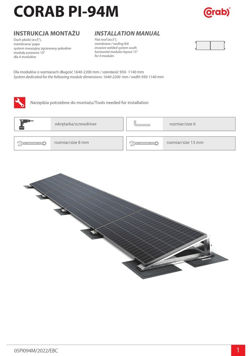
OutBack Power smartharvest User manual

031-331-B1-001, Rev. A (11/2015) 1
Quick Start Guide
SmartHarvest™Pole-Mounted PV Solar Power Station
The SmartHarvest™ Pole-Mounted PV Solar Power Station is composed of a number of pre-installed, pre-wired subsystems.
Before proceeding with the installation, verify which charge controller is installed, review this guide to become familiar with the
various subsystems. Adhere to the electrical and mechanical safety guidelines indicated in this document, as well as all related
documentation for each subsystem.
Refer to the following documents for comprehensive installation instructions and safety information.
Enclosure:
• Alpha Technologies Alpha Pole Mount Bracket Installation Guide (Alpha p/n 745-968-C0)
Charge Controllers:
• SmartHarvestTM SCCM20-100 MPPT Charge Controller/Load Manager
• Morningstar TriStar MPPT TM -30 Solar Charge Controller, (Morningstar p/n MS-000946 v05.1)
Solar Module Racking System, Side of Pole Mount (SPM) –The actual racking system will be determined by the size and
power capacity of the system.
• DPW Solar Side-of-Pole Mount (SPM1) Assembly Instructions
• DPW Solar Side-of-Pole Mount (SPM2) Assembly Instructions
• DPW Solar Side-of-Pole Mount (SPM3) Assembly Instructions
Photovoltaic Modules:
• ET Solar Photovoltaic Modules User Manual
Batteries:
• OutBack Power Technologies EnergyCell Battery Owner's Manual (OutBack Power Technologies p/n 900-0127-01-00)
Audience
This guide is intended for experienced installers familiar with the mechanical and electrical requirements of photovoltaic systems
and qualied, licensed installation personnel. Review all included documentation to become familiar with all of the features and
functions of the equipment in this system before proceeding. Failure to install and/or use this equipment as instructed in the
system documents can result in damage to the equipment. This system is only serviceable by qualied personnel.
Safety Guidelines
Separate safety documentation, as well as technical manuals for the racking system, PV modules, charge controller, enclosure and
batteries are available online. and contain additional product-specic safety information, detailed installation and conguration
information. Comprehensive safety information is contained in OutBack Power Technologies' Important Safety Instructions.
Classes of Symbols used in these documents
WARNING: Hazard to Human Life
This type of notation indicates that the hazard could be harmful to human life.
CAUTION: Hazard to Equipment
This type of notation indicates that the hazard may cause damage to the equipment.
IMPORTANT:
This type of notation indicates that the information provided is important to the installation, operation and/or maintenance of
the equipment. Failure to follow the recommendations in such a notation could result in voiding the equipment warranty.

031-331-B1-001, Rev. A (11/2015)031-331-B1-001, Rev. A (11/2015)
23
Site Characteristics
In the northern hemisphere, always orient the array to true south. In the southern hemisphere, always orient the array to true
north. To optimize power output, verify that no object, including fencing, trees, buildings and/or other obstructions, will cause any
shading of the array.
Site Latitude Fixed Tilt Angle
0° to 25° 30°
25° to 30° Latitude +5°
30° to 35° Latitude +10°
35° to 40° Latitude + 15°
> 40° 60°
Components that determine tilt
Simplied System Block Diagram
The PV module(s) convert solar energy into DC power which is then fed to the positive (+) and negative (–) terminals on the
charge controller. The design of the charge controller allows for uniform charging of the battery bank and prevents overcharging
conditions. The batteries provide power for loads appropriately rated for the battery string (12Vdc to 48Vdc).
PV Module Tilt
Refer to the accompanying table for recommended tilt angles. The tilt angle is set by the vertical distance (span) between the pole
channels, the selection of an attachment point (a, b, or c) and the length of the strut.
For comprehensive information regarding installation and assembly of the Side-of-Pole mounting rack, refer to DPW Solar's
Side-of-Pole Mount Assembly Instructions.
WARNING: Personal Injury
Use care while assembling the rack assembly. During the assembly procedure components could create hazards, obstructing
free movement and leading to serious bodily injury. These hazards are at head/eye level. The use of head and eye protection is
required.
IMPORTANT:
The SPM-1 racking system is designed for poles 2" to 3.5" in diameter. The SPM-2 and SPM-3 racking systems are designed for poles
3" to 4.5" in diameter.
Mounting Rack Assembly
Item Description Quantity
1 Hose Clamp (standard) 4 per rack
2 Pole Channel 2 per rack
3 Module Rail (left and right) 2 per rack
4 3/8" x 1" hex bolt, lock washer, at washers 6 sets per rack
5 Strut 2 per rack
6 1/4" x 3/4" hex bolt, lock washer, at washers, nut 4 sets per rack
Item Description
1 Pole Channel
2 Module Rail (left and right)
3 Strut (left and right)
Attachment Points
a
b
c
Span
2
1
1
3
Tools required for racking assembly:
• 7/16" wrench for 1/4" module hardware
• 9/16" wrench for 3/8" hardware
• Torque wrench (optional, recommended)
• Ratchet and extension bar
• Safety eyewear
• Safety headgear
PV
modules
Charge Controller
PV Module breaker
(+)
(–)
PV BATT LOAD
Load circuit breaker
Load (+)
Load (–)
(–)
(+) (–)
(+) (–)
(+)
Battery breaker Negative bus bar
Battery string(s)
1
2
45
1
2
4
4
4
4
4
5
3
3
6
6
6
6
Illustration courtesy of DPW Solar / Preformed Line Products
Illustration courtesy of DPW Solar / Preformed Line Products
IMPORTANT:
The size and capacity of the system determine which charge controller, either the SmartHarvest by OutBack
SCCM20-100 MPPT or Morningstar TriStar MPPT-30, is installed in the system. Verify the particular make and model in
the system and follow instructions in this and related product documentation

031-331-B1-001, Rev. A (11/2015)031-331-B1-001, Rev. A (11/2015)
45
PV Module Connections
Pole-mounted systems will use either Alpha Technologies' PWE-3 or PWE-6 enclosures. Refer to the Alpha Pole Mount Installation
Guide (745-968-C0) for complete installation and conguration instructions. Read and follow all safety instructions contained in
the manual.
IMPORTANT:
The enclosure must only be installed by qualied personnel.
Enclosure Installation
Mounting the Photovoltaic (PV) Module
PV modules are secured to the mounting rails using 1/4" x 3/4" bolts, with hardware tightened to a torque setting of 7 ft-lb.
Refer to ET Solar Series Photovoltaic Modules User Manual for additional information.
Warning: Electrical Hazard
Photovoltaic modules convert light energy to DC power and are designed for outdoor use. Proper design of support structures
is the responsibility of the system designer and installer. Cover modules with opaque material until modules are installed and
connected to the PV circuit breaker.
WARNING: Personal Injury
Due to the weight and size of the PV module, two installers are required to attach the PV module to the rails.
1
2
1
2
PV module/SmartHarvest Charge Controller connections
PV module positive (+): Connect to the lower position of PV input circuit breaker.
PV module negative (–): Connect to the charge controller PV negative (–).
PV module/TriStar Charge Controller connections
PV module positive (+): Connect to the lower position of PV input circuit breaker.
PV module negative (–): Connects directly to the negative bus bar.
CAUTION: Hazard to Equipment
In systems congured with a SmartHarvest Charge Controller: Connect PV module negative (–) directly to PV negative (–)
point on the charge controller.
In systems congured with a TriStar Charge Controller: Connect PV module negative (–) to the negative bus bar; the connection
between the negative bus bar and PV negative (–) on the charge controller is pre-wired.
Each system requires the PV module connections to be made as shown above. Connecting the PV modules with reversed polarity
will damage the charge controller.
IMPORTANT:
All PV modules must be wired in series.
1/4" x 3/4" Bolt
Flat Washer
Flat Washer
Lock Washer
1/4" Nut
PV Module wiring to SmartHarvest Charge Controller
1
2
Positive (+)
Negative (−)
PV Module
Input
PV Module wiring to TriStar Charge Controller
12
PV Module
Input
Positive (+)
Negative (−)
Illustration courtesy of DPW Solar / Preformed Line Products

031-331-B1-001, Rev. A (11/2015)031-331-B1-001, Rev. A (11/2015)
67
Required Tools
• 7/16" wrench for 1/4" hardware
• 9/16" wrench for 3/8" hardware
• Torque wrench
• Torque screwdriver
Battery Installation Battery Connections
Battery String(s)
Battery positive(s) (+) are pre-wired to the DC bus via circuit breakers and battery negative(s) (–) are connected to the negative
bus bar. Cables are terminated with ring lugs. Connect the cables to battery positive (+) and negative (–) terminals. The charge
controllers can provide battery sense voltage as well as remote temperature sensing. Pair the battery sense wires with the longest
leads in the battery cable kit and connect them to the same battery. Connect the remote temperature sensor (if used) to a point in
the center of the highest battery string.
Battery Specications
• Slotted screwdriver
• #2 Phillips screwdriver
• Pozidriv #2 Combi head
• Digital voltmeter (DVM)
CAUTION: Equipment Damage
Never reverse the polarity of the battery cables. Always verify correct polarity.
WARNING: Fire Hazard
Always ensure a circuit breaker or overcurrent device is installed on the DC positive conductor for each device connected
to the batteries.
WARNING: Fire Hazard
Never install extra washers or hardware between the mounting surface and the battery cable lug or interconnect. The decreased
surface area can build up heat.
WARNING: Personal Injury
• Some batteries can weigh in excess of 69 lb (31 kg). Use safe lifting techniques when lifting this equipment as prescribed by
the Occupational Safety and Health Association (OSHA) or other local codes. Lifting machinery may be necessary.
• Wear appropriate protective equipment when working with batteries, including eye or face protection, acid-resistant
gloves, an apron, and other items. Avoid touching bare skin or eyes while working near batteries.
• Keep plenty of fresh water and soap nearby in case battery acid contacts skin, clothing, or eyes.
• If battery acid contacts skin or clothing, wash immediately with soap and water.
• If acid enters the eye, immediately ood it with running cold water for at least 20 minutes and get medical attention as soon
as possible.
• Wash hands after any contact with the lead terminals or battery electrolyte.
WARNING: Explosion, Electrocution, or Fire Hazard
• Ensure clearance requirements are strictly enforced around the batteries.
• Ensure the area around the batteries is well ventilated and clean of debris.
• Never smoke or allow a spark or ame near the batteries.
• Always use insulated tools. Avoid dropping tools onto batteries or other electrical parts.
• Never charge a frozen battery.
• Insulate batteries as appropriate against freezing temperatures. A discharged battery will freeze more easily than a
charged one.
• If a battery must be removed, always remove the grounded terminal from the battery rst. Make sure all devices are
de-energized or disconnected to avoid causing a spark.
• Do not perform any servicing other than that specied in the installation instructions unless qualied to do so and have
been instructed to do so by OutBack Technical Support personnel.
Battery Model Specications
EnergyCell RE Top Terminal 78RE 106RE
Nominal Voltage per cell 12Vdc 12Vdc
Capacity Rates (1.75VPC) 20Hr: 75Ah 100Hr: 78Ah 20Hr: 100Ah 100Hr: 106Ah
Cycle Life (50%DOD @25°C) 1800 cycles 1800 Cycles
Float Cycle Life (@25°C) 10 years 10 years
Weight (lbs) 54 69
Dimensions L x W x H (in) 10.2 x 6.8 x 8.0 13.5 x 6.8 x 8.5
Warranty 2 years 2 years
Additional battery information is available in OutBack Power Technologies' EnergyCell Battery Owner's Manual.
• Work gloves
• Safety glasses
• Battery spill clean-up kit
To negative bus bar
To DC input breakers
12Vdc battery bank
Hardware arrangement, EnergyCell 78RE, 106RE
top terminal batteries
Battery Sense
Cable (RTS)
Battery Cable
3/4" x 1/4-20 Bolt
Battery Terminal
Lock Washer
Flat Washer
–
+
–
+
To negative bus bar
24Vdc battery bank, 3 strings of 12Vdc batteries wired in series
To DC input breakers
–
+
–
–
+ +
–
+
–
+
–
+
–
+
To negative bus bar
24Vdc battery bank, 2 x 12Vdc batteries wired in series
To DC input breakers
–
–
+ +

031-331-B1-001, Rev. A (11/2015)031-331-B1-001, Rev. A (11/2015)
89
Circuit Breaker Specications
Wire Size mm2 (IEC) 0.75 to 35 mm2
Wire Gauge (UL) 18 to 2 AWG
Torque (IEC) 2.5 Nm
Torque (UL) 20 in-lb
Comments Pozidriv #2 Combi head
WARNING: Electrical Hazard
Only qualied personnel should install and wire the system or have access to the inside of the enclosure.
Wiring the System, SmartHarvest SCCM20-100 Charge Controller
The system is shipped with the bulk of the wiring connections already in place. Remove the xing screw on the underside of the
cover plate to expose the connection terminals and make connections as shown. Verify pre-existing wiring is still in place and
tightened to proper torque settings. Replace the cover plate after inspecting the connections.
1
2
3
4
5
PV module connections
PV module positive (+) to PV breaker
PV module negative (–) to charge controller negative (–)
Charge Controller connections
PV module breaker to charge controller PV positive (+)
Battery positive (+) from charge controller to master DC circuit breaker
Battery negative (–) from charge controller to negative bus bar
6
7
11
6
7
9
10
11
8
Battery string connections
String #1 positive (+)
String #2 positive (+)
String #3 positive (+)
String #1 negative (–)
String #2 negative (–)
String #3 negative (–)
Load connections
Charge controller DC (+) to load output circuit breaker
DC output voltage positive (+)
DC output voltage negative (–)
Ground connection
12
13
14
9
10
8
3
4
5
12
14
A
A
B
C
PV module circuit breaker
DC bus master breaker
Load output circuit breaker
2
3 4 5 12 14
Charge Controller connection detail, including optional battery
sense wiring and remote temperature sensor wiring
Battery temperature sensor (optional);
connect to battery (+) terminal
Battery sense wire; connect to
battery (+) terminal
B
1
2
C
Terminal block torque
0.9 Nm / 8 in-lb
15
15
13
System Startup, SmartHarvest SCCM20-100 Charge Controller
CAUTION: Hazard to Equipment
Reversed polarity will damage the charge controller.
CAUTION: Hazard to Equipment
Failure to close the battery breakers before closing the PV breaker will damage the charge controller.
IMPORTANT:
The SCCM20-100 requires a minimum load to wake up from sleep mode. Refer to SCCM20-100 manual for details.
Before Startup:
• Verify the PV breaker is open.
• Verify the DC bus master breaker and any used battery string breakers are open.
• Verify the load breaker is open.
Startup Procedure
1. Close the connected battery string breaker(s).
2. Close the DC master breaker. The three LEDs on the front panel of the charge controller will ash once and go out.
3. Close the PV input breaker. The three LEDs on the front panel of the charge controller will ash once, then remain o. After approximately
20 seconds, the green LED will light and be on solid, indicating the presence of PV input. The yellow LED will blink indicating the state of
charge of the battery string.
4. Measure across the Load positive (+) and Load negative (–) terminals on the charge controller. The voltage measured should match the
battery string voltage.
5. Close the Load breaker and measure between the load terminal positive (+) and negative (–). The voltage measured should match the
voltage measured at the charge controller.
ABC
APV module circuit breaker BDC bus master breaker CLoad output circuit breaker

031-331-B1-001, Rev. A (11/2015)031-331-B1-001, Rev. A (11/2015)
10 11
Charge Control / Load Control
LEDs on the SmartHarvestTM SCCM20-100 Charge Controller indicate battery state, operational status and alarm conditions as
indicated in the table below.
Indications/Alarms, SmartHarvest SCCM20-100 Charge Controller
SmartHarvest SCCM20-100 LED Indicators
Load LED
(Red)
Solid Load disconnected
Slow ash Battery load critical – Charge < 20%
O OK – no error
Battery LED
(Yellow)
Solid Battery charge >90%
Slow ash Battery charge >50%
Rapid ash Battery charge <50%
O Battery critical < 20%
PV LED
(Green)
Solid PV present
Slow ash Battery charging
O No PV present
Troubleshooting
Problem Possible remedies (perform in order shown)
Battery not charging 1) Check battery connections
2) Check PV voltage and connections
3) Check breakers.
4.) Allow charger to cool
No LED indicators with PV power available 1) Check battery voltage at controller terminals
2) Check panel voltage at controller terminals
Red LED on 1) Disconnect load
2) Disconnect PV
3) Disconnect battery
4) Reconnect battery
5) Reconnect PV
6) Reconnect load
Red LED ashing 1) Disconnect loads
2) Recharge battery
Yellow LED not on Charge battery
Charging to wrong voltage 1) Check position of battery selection jumper
2) Check installation of thermistor
Load not powered Check minimum load for charge controller
System Shutdown, SmartHarvest SCCM20-100 Charge Controller
1. Open the Load output breaker.
2. Open the PV input breaker.
3. Open the master DC circuit breaker.
4. Open any connected battery breakers.
5. Measure across the Load positive (+) and Load negative (–) terminals on the charge controller. Verify a reading of 0 Vdc, indicating
the system is oine.
ABC
APV module circuit breaker BDC bus master breaker CLoad output circuit breaker
WARNING: Electrical Hazard
Prior to beginning the shutdown procedure, cover the PV modules with opaque material to prevent the conversion of light energy
into DC power.
CAUTION: Hazard to Equipment
Opening the battery breakers before opening the PV or load breaker will damage the charge controller.
CAUTION: Hazard to Equipment
The master battery breaker must be opened during periods of no solar input that extend beyond the rated 3 day blackout
autonomy e.g. solar panel service, prolonged snow cover, debris build up on panel. Failure to either recharge the batteries or open
the master battery breaker during an extended outage may result in permanent damage to the batteries.

031-331-B1-001, Rev. A (11/2015)031-331-B1-001, Rev. A (11/2015)
12 13
Wiring the System, Morningstar TriStar MPPT-30 Charge Controller
3
4
5
Connection detail, charge controller termination board
PV module positive (+) to the charge controller PV positive (+)
Battery positive (+) from the charge controller to the master DC circuit breaker
Battery negative (–) from the charge controller to the negative bus bar
Charge Controller connections, LEDs, battery sense wiring and remote
temperature sensor wiring
Battery temperature sensor
Battery sense positive (+)
Battery sense negative (–)
34
5
To enclosure ground
Illustrations courtesy of Morningstar Corp.
LED indicators
Three LED indicators provide information
regarding general controller transitions, battery
status, controller faults and alarms.
Green
Yellow
Red
ABCD
6
Wiring the System, Morningstar TriStar MPPT-30 Charge Controller
Circuit Breaker Specications
Wire Size mm2 (IEC) 0.75 to 35 mm2
Wire Gauge (UL) 18 to 2 AWG
Torque (IEC) 2.5 Nm
Torque (UL) 20 in-lb
Comments Pozidriv #2 Combi head
7
8
9
10
11
12
13
14
15
Battery string connections
String #1 positive (+)
String #2 positive (+)
String #3 positive (+)
String #1 negative (–)
String #2 negative (–)
String #3 negative (–)
Load connections
Battery bus to LVD positive (+)
LVD negative (–) to negative bus bar
LVD (Load) to Load output circuit breaker
DC output voltage positive (+)
DC output voltage negative (–)
Ground connection (–)
Teminal block wiring torque value = 0.9 Nm / 8 in-lb
PV module connections
PV module positive (+)
PV module negative (–)
Charge Controller connections
PV module positive (+) to charge controller PV positive (+)
Battery positive (+) from charge controller to DC bus master
circuit breaker
Battery negative (–) from charge controller to negative bus bar
1
2
3
4
5
APV module breaker BDC bus breaker CLow voltage disconnect (LVD) DLoad output breaker
WARNING: Electrical hazard
Only qualied personnel should install and wire the system or have access to the inside of the enclosure.
The system is shipped with the bulk of the wiring connections already in place. Use a #2 Phillips screwdriver to remove the four
(4) screws that secure the wiring box cover. Verify the pre-existing wiring is still in place and tightened to proper torque settings.
Replace the cover after inspecting the connections.
67
4
3
1
212
5
9
11
10
8
13
14
16
IllustrationofMorningstarTriStarMPPT-30ChargeControllercourtesyofMorningstarCorp.
17
15
Terminal block torque
0.9 Nm / 8 in-lb
16
17

031-331-B1-001, Rev. A (11/2015)031-331-B1-001, Rev. A (11/2015)
14 15
Indications/Alarms, Morningstar TriStar MPPT-30 Charge Controller
with PT-10 Low Voltage Disconnect
Charge Control / Load Control
LEDs on the Morningstar TriStar MPPT-30 Charge Controller indicate battery state, operational status and alarm conditions as
listed in the table below. Detailed information regarding alarm states can be found in the TriStar MPPT-30 Solar System Controller,
technical manual (p/n MS-000946 v05.1)
TriStar TS-MPPT-30 LED Indicators
General Transitions LED Indications
Controller start-up Green / Yellow / Red (one cycle)
Equalize request start Green + Yellow + Red / Green + Yellow + Red / Green / Green
Equalize cancelled Green + Yellow + Red / Green + Yellow + Red / Red / Red
Battery service is required* All 3 LEDs blinking until service is reset
*Battery service notication is only enabled in custom settings
Battery Status (General State of Charge) LED Indications
80% to 95% Green
60% to 80% Green + Yellow
35% to 60% Yellow
0% to 35% Yellow + Red
Battery is discharging Red
Absorption state Green blinking (½ second on / ½ second o)
Equalization state Green fast blink (2.5 times per second)
Float state Green slow blink (1 second on / 1 second o)
Faults & Alarms LED sequence; repeating until the fault is cleared
Over-temperature Yellow / Red (sequencing)
Battery high voltage disconnect Green / Red (sequencing)
DIP switch fault or DIP switch changed Red / Yellow / Green (sequencing)
Self-test faults Red / Yellow / Green (sequencing)
Custom settings edit Red / Green / Yellow (sequencing)
Remote Temperature Sensor (RTS) Green + Yellow / Yellow + Red (sequencing)
Battery voltage sense failure Green + Yellow / Yellow + Red
System Startup, Morningstar TriStar MPPT-30 Charge Controller
Before Startup:
• Verify the PV disconnect is open.
• Verify the Battery disconnect and any used battery string disconnect(s) are open.
• Verify the load disconnect is open.
Startup Procedure
1. Conrm the polarities of the PV module wiring and Battery string wiring are correct.
2. Close the connected battery string breakers (1 through 3).
3. Close the master battery disconnect. The LEDs on the charge controller will sequentially blink one cycle of Green-Yellow-Red, indicating
a successful startup.
ACD
IllustrationofMorningstarTriStarMPPT-30ChargeControllercourtesyofMorningstarCorp.
APV disconnect BBattery disconnect CLow voltage disconnect (LVD), Model PT10 DLoad disconnect
CAUTION: Hazard to Equipment
Reversed polarity will damage the charge controller.
CAUTION: Hazard to Equipment
Failure to close the battery breakers before closing the PV breaker will damage the charge controller.
Dual-color LED
indicates normal
operating state or
alarm state.
NOTE:
A battery must be connected to the TriStar MPPT to start and operate the controller. The controller will not operate only from
solar input.
4. Close the PV disconnect. The color and activity of the LEDs will indicate the state of charge of the battery string.
5. Close the Load disconnect. The green LED on the Low Voltage Disconnect device will be on solid indicating battery voltage is
within the disconnect (10.5 Vdc) and reconnect (12.5 Vdc) voltage limits as set by the factory.
6. Measure across the Load positive (+) and Load negative (–) on the charge controller to verify the battery voltage.
Battery
strings B
123
Low Voltage Disconnect (Model PT10)
Event Result Indication Action
Normal operation Low voltage disconnect is closed;
voltage supplied to load Green LED is on solid None required
Battery voltage decreases to disconnect
level (10.5Vdc)
Low voltage disconnect opens and
removes load from batteries.
Red (Alarm) LED is on
solid. Recharge batteries.
Battery voltage increases to reconnect
level (12.5Vdc)
Low voltage disconnect closes and
reconnects load to batteries.
Alarm LED switches
from Red to Green; LED
is on solid
Load reconnected;
No action required.
The dual-color LED on the PT-10 Low Voltage Disconnect indicates whether the unit is in normal operation or in an alarm state as
indated in the table below.

member of
The Group
T
M
Worldwide Corporate Oces
North America
Tel: +1 360.435.6030
Fax: +1 360.435.6019
Europe
Tel: +49 9122.79889.0
Fax: +49 9122.79889.21
Latin America
Tel: +1 561.792.9651
Fax: +1 561.792.7157
Asia Pacic
Tel: +852 2736.8663
Fax: +852 2199.7988
031-331-B1-001 Rev. A (11/2015)
System Shutdown, Morningstar TriStar MPPT-30 Charge Controller
1. Open the load output circuit breaker (the Green LED on the LVD will remain on).
2. Open the PV module circuit breaker.
3. Open the DC bus master circuit breaker (the Green LED on the LVD will turn o at this time).
4. Open any connected battery breakers.
5. Measure across the Load positive (+) and Load negative (–) on the charge controller. Verify a reading of 0 Vdc, indicating
the system is oine.
ABCD
IllustrationofMorningstarTriStarMPPT-30ChargeControllercourtesyofMorningstarCorp.
APV module breaker BDC bus breaker CLow voltage disconnect (LVD) DLoad output breaker
WARNING: Electrical Hazard
Prior to beginning the shutdown procedure, cover the PV modules with opaque material to prevent the conversion of light energy
into DC power.
CAUTION: Hazard to Equipment
Opening the battery breakers before opening the PV or load breaker will damage the charge controller.
CAUTION: Hazard to Equipment
The master battery breaker must be opened during periods of no solar input that extend beyond the rated 3 day blackout
autonomy e.g. solar panel service, prolonged snow cover, debris build up on panel. Failure to either recharge the batteries or open
the master battery breaker during an extended outage may result in permanent damage to the batteries.
Table of contents
Popular Solar Panel manuals by other brands
Dea
Dea Green Energy kit Operating instructions and warnings
Qcells
Qcells Q.ANTUM DUO Z Series Installation and operation manual
GOAL ZERO
GOAL ZERO BOULDER30 user guide
CORAB
CORAB PB-066 installation manual
Qcells
Qcells Q.PEAK DUO XL-G11.2 Series Installation and operation manual

Qcells
Qcells Q.MAXX-G3 Series Installation and operation manual
