Roofit.Solar Double Seam User manual

Double Seam
Installation
Manual.
Please read Roofit.solar Safety Manual cerafully before initiating any Roofit.solar system installation.

2Double Seam Installation Manual
Root.solar Double Seam Panel
Root.solar panels are building integrated photo-
voltaic (BIPV) construction elements which replace
conventional roong and facade materials.
A Root.solar panel has two parts: an overlapping area and
an ‘active PV area’. The overlapping area on top of the panel is
designed to ensure a waterproof connection between the two
adjacent panels on the roof. The overlapping area on the roof
must be a minimum of 200 mm.
Electricity is produced in a thin active photovoltaic layer that covers
the most part of the panel.
Active PV area
Overlapping area
Tempered glass
Anti-reective
Metal back sheet
PUR coating
Photovoltaic cell
Junction boxes
Connectors
Please read Roofit.solar Safety Manual cerafully before initiating any Roofit.solar system installation.

3Double Seam Installation Manual
Installation Roof Accessories
Ridge cap Chimney ashing
Valley ashing Window ashing
Gable border
Eave ashing
Ridge caps are designed
to cover the ridge of
the roof and shield
against seepage.
Ridge Cap
Valley ashings are
installed before
the prole sheet
and followed by
the roof slates.
Valley Flashing
Chimney ashings are
used to join the roof
sheet and chimney
together, ensuring
that the roof
repels water at the
base of the chimney.
Chimney Flashing
Gable borders are
attached to the board
of the end eave,
nishing the edge
of the roof and
protecting it from
dampness.
Gable Border
Eave ashings
carry rainwater
from the roof to
the gutter.
Eave Flashing
Please read Roofit.solar Safety Manual cerafully before initiating any Roofit.solar system installation.

4Double Seam Installation Manual
Ridge support elements
are designed to more
eectively fasten the ridge
cap in place and
provide complete
water-proong.
Ridge Support Element Sealant
Sealant is designed
to support adhesion
between the overlapping
areas of panels.
Screws
Flat-head self-tapping
screws are designed
to fasten
Double-sided Tape
Double-sided tape is
needed to enhance
the fastening of over-
lapping fastening
elements.
Overlapping fastening
elements are
designed to more
eectively fasten
overlapping areas.
An overlapping element is
laid using tape and then
screwed into place.
Overlapping
Fastening Element
Fastening Clamps
Fastening clamps are
for fastening modules
on to battens.
Seaming tools
Seaming tools are
to seam locks and
complete the
roong process.
Both the standing-seam/
rolled prole roof system
and the click system can be
used with Root.solar panels.
The installation of these systems
is as easy as conventional
roof installation.
Please read Roofit.solar Safety Manual cerafully before initiating any Roofit.solar system installation.

5Double Seam Installation Manual
1. Installation of Purlins
and Rafters
1.1 Installation of battens which are the most common support
structure in metal roof installations, plays an important role when
installing Root.solar panels. Wooden blanks should be laid on
top of the anti-condensation lm covering the roof base accord-
ing to both the angle of the roof and the snow load.
1.2 Double seam installation is applicable for roof inclination that
exceeds 10 degrees (Fig. 1); the battens should be laid every
250-300 mm, parallel to the rst fastened row (Fig. 2).
Fig. 1 Fig. 2
> 10º
250 mm - 300 mm
Please read Roofit.solar Safety Manual cerafully before initiating any Roofit.solar system installation.

6Double Seam Installation Manual
1.3 If the snow load is high, battens can be laid more closely
together on the lower side of the roof. However, the cables
of the Root.solar panels must run between the battens,
so the battens must be installed accordingly.
1.4 The junction boxes under each panel must t between two
battens, without touching either (Fig. 3). The junction boxes
are located behind the Root.solar panels, starting from the edge
of the ‘active PV area’ and ending 50 mm below the ‘active PV
area’ edge.
Fig. 3
Junction boxes
Connectors
No batten zone
Please read Roofit.solar Safety Manual cerafully before initiating any Roofit.solar system installation.

7Double Seam Installation Manual
2. Cutting Locks / Edges:
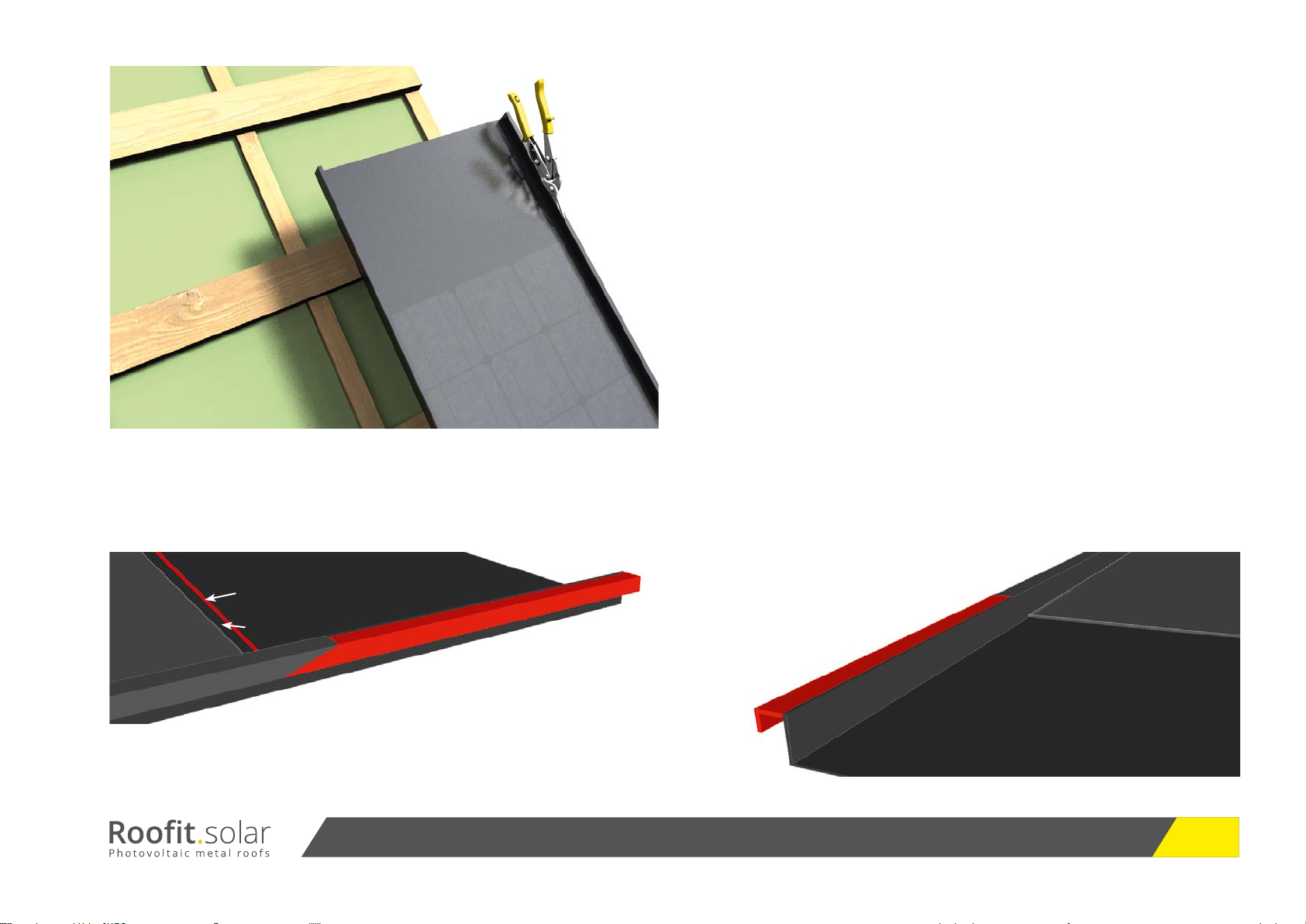
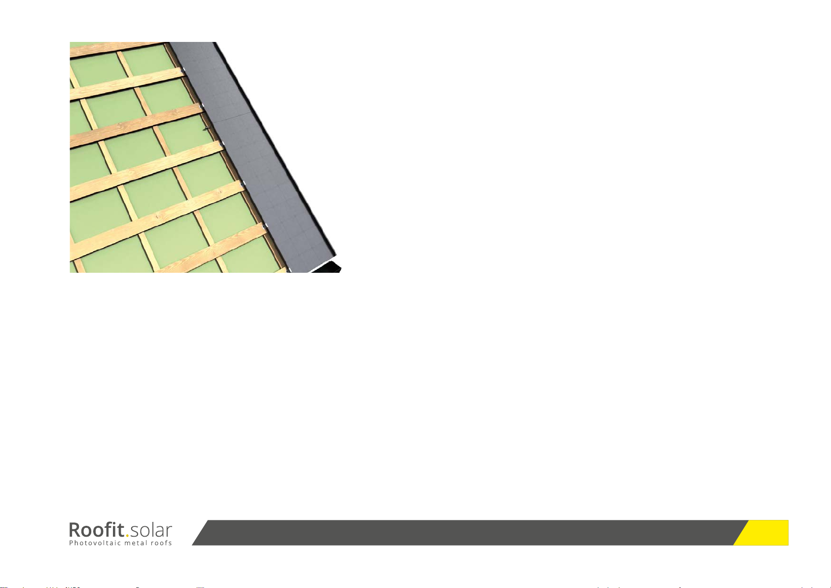
Depending on the length of the roof, the distance of the overlap
(the point where one Root.solar panel joins another) may vary.
The overlapping area must be a minimum of 200 mm. Due to
thermal expansion, subsequent Root.solar panels which extend
to the overlapping area should be 3 mm away from the previ-
ous panel.
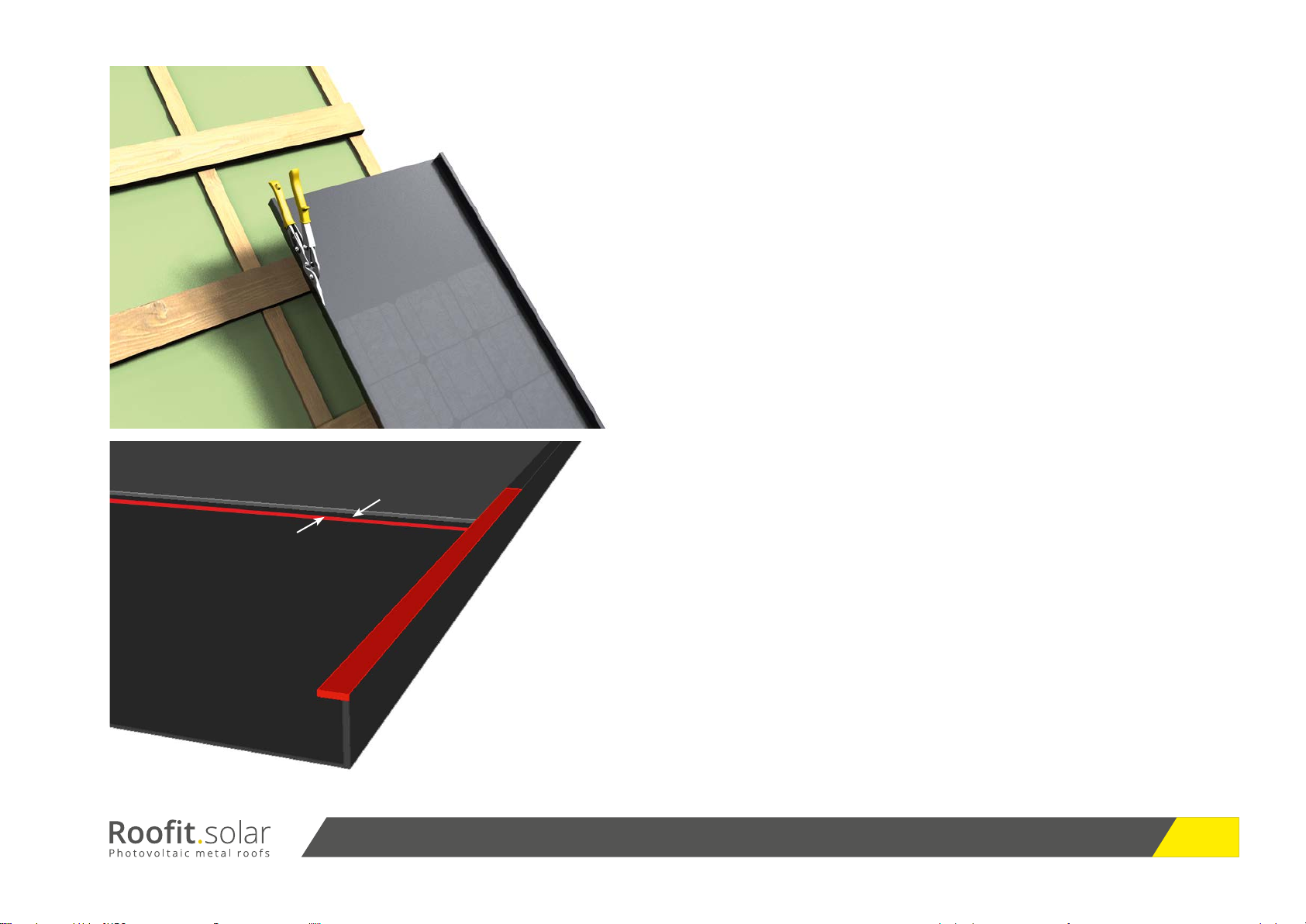
2.1 Cutting higher lock is shown accordingly in Figure 4, 4 a and
4 b. Starting from line where the Root.solar module overlaps with
the next one, the cut should start from outside of the lock with
the angle of approximately 30 degrees as it is shown in Figure 4 a,
till it reaches the edge. Then, the cut continues perpendicular to
module alignment until it reaches the end of upper part of the
lock. After that, the cut continues till the upper part of the lock is
completely cut out as it is shown in Figure 4 b.
Fig. 4
Fig. 4 a Fig. 4 b
Line for next
module
Active
PV Area
Overlapping Area
min. 3 mm
Overlapping Area
Active
PV Area
Please read Roofit.solar Safety Manual cerafully before initiating any Roofit.solar system installation.

8Double Seam Installation Manual
Cutting higher lock is shown accordingly in Figure 5 and 5 a.
Starting from the line where the next Root.solar module comes,
the cut starts continues vertically to module alignment, until the
upper part of the lock reached to an end (Fig. 5 a)
Then, the cut continues parallel to alignment until all upper part
of the lock is cut o.
Fig. 5
Fig. 5 a
Overlapping Area
Active PV Area
Level of next
module
3 mm
Please read Roofit.solar Safety Manual cerafully before initiating any Roofit.solar system installation.

9Double Seam Installation Manual
3. Installation of First Column
Since Root.solar has an active PV area that must
not be bent or folded, the rst column touching the
gable border should consist of regular metal panels.
3.1 After the installation of the rain shadow border, the rst Root.
solar panel should be installed running from right to left, perpen-
dicular to the rain shadow line and parallel to the gable channel.
3.2 The joining edge of the Root.solar panel must be cut from
the locks till the ‘active PV area’ in order to enhance fastening
on the overlap as it was shown in Section ‘Cutting Locks/Edges’
3.3 The bottom of the lowest Root.solar panel that extends
to the eave cannot be cut and folded like a regular metal panel.
The ‘active PV area’ on Root.solar panels provide excellent
water-tightness and prevents metal expansion due to tempera-
ture increase.
Please read Roofit.solar Safety Manual cerafully before initiating any Roofit.solar system installation.

10Double Seam Installation Manual
Fig. 6
Fig. 7
3.4 Junction box cables should be in reachable position before
fastening the panels to the battens. The Root.solar panels on the
roof will form electrically one or several series-connected strings
whose ends are connected to the inverter (Fig. 6). Make sure
that the cables are engaged till the very end and ‘clicked’.
3.5 The cable dust caps, which provide protection from mois-
ture and the outside environment, must be removed immedi-
ately prior to making the click connection between the MC4
connectors (Fig. 7).
3.6 After placing the bottom part on the rain gutter, higher lock
(right side) of the rst column will be fastened by using
fastening clamps to the battens. The clamps will be laid in
approximately every 400 mm (Fig. 8).
To DC/AC
Inverter
Please read Roofit.solar Safety Manual cerafully before initiating any Roofit.solar system installation.

11Double Seam Installation Manual
3.7 Left side of the rst column and upcoming Root.solar or
regular metal panels must also be fastened to the battens by fas-
tening clamps that lay every 400 mm after ensuring the junc-
tion box cable must be accessible later (Fig. 8).
3.8 The upper part of the panel (where the overlapping area is)
should then be prepared for the second panel by using three
layers of adhesive sealant (Fig. 9).
3.9 The second row and remaining upper rows of the rst column
are fastened in the same way.
Fig. 8
Fig. 9
Please read Roofit.solar Safety Manual cerafully before initiating any Roofit.solar system installation.

12Double Seam Installation Manual
3.10 In cases for upper rows of any column are covered with
regular metal panel rather than Root.solar panel, overlap-
ping must be made by:
a. First, cutting the locks of regular metal panel as in Root.solar
module as it is shown in Section ‘Cutting Edges/Locks’.
b. Leaving a 25 mm space for folding (Fig.11).
c. Putting double tape to the overlapping area of Root.solar
panel that will join regular metal panel (Fig. 12).
d. Fastening small overlapping element by at headed screws
(Fig. 13).
e. Then placing folded part of regular metal panel that was
prepared under the fastened small overlapping element (Fig. 14).
Fig. 10
Fig. 11 Fig. 12
Regular metal
overlapping
Line for folding
25 mm
Please read Roofit.solar Safety Manual cerafully before initiating any Roofit.solar system installation.

13Double Seam Installation Manual
Fig. 13 3.11 In case where upper rows of any column is covered with
Root.solar modules, then overlapping process is the same (put-
ting three layers of sealant).
Fig. 14
Please read Roofit.solar Safety Manual cerafully before initiating any Roofit.solar system installation.

14Double Seam Installation Manual
4. Installation of Second
Column and the Rest
4.1 Once rst column is fastened on the roof, second and the
rest of the columns are fastened after junction cable are con-
nected (Fig. 15), and the locks are seamed by rst using rst hand
tool (Fig. 16 a), and double lock by using the second hand tool
(Fig. 16 b).
Fig. 15
Fig. 16 a Fig. 16 bFig. 16
Please read Roofit.solar Safety Manual cerafully before initiating any Roofit.solar system installation.

15Double Seam Installation Manual
Since the active part of Root.solar panels must not
be cut or bended, it is recommended to leave some
distance around roof accessories such as eaves,
gables, valley ashings, ridge tunnels, and window
and chimney ashings.
5.1 The recommended distance for gables, chimney ashings,
ridges, are 150 mm; for window ashings and valley ashings,
the distance should be approx. 300 mm. Fastening a Root.
solar module to the space around these roof elements at smaller
distances is not possible, so these areas should be fastened with
regular metal panels only.
These values may vary for each roong material suppli-
er. Consult a local roong specialist to get your accessories
dimensions before designing the PV system (Fig. 17).
5.2 Apart from chimney ashing, a distance as equal as height of
the chimney must be spared from Root.solar modules due to
shadow. This ‘height rule’ applies to all external erupted parts on
the roof including dormers and ventilation tubes.
5. Installation of Root.solar
Panel around Roof Accessories
Fig. 17
Fig. 18
Please read Roofit.solar Safety Manual cerafully before initiating any Roofit.solar system installation.

16Double Seam Installation Manual
5.3 In cases where a valley ashing extends to the overlapping
metal part of the Root.solar panel, the overlapping metal part
should be marked and cut following the line of the overlapping
element of the valley ashing already installed (Fig.18).
5.4 Apart from chimney ashing, a distance as equal 1. In areas
where the overlapping metal part is diagonally cut as in Figure,
the cut should start at least 100 mm from the active area. Do not
cut or bend the metal closer than 100 mm to the ‘active PV
area’ (Fig. 19).
5.5 Roof accessories like chimney and window ashings, ridge
caps and gable borders can easily be installed as on regular metal
roofs.
5.6 Before installing the ridge cap, the uppermost Root.solar
panel which extends approx. to the middle of the roof length
must be selected to ground the installed system (Fig. 20).
Fig. 19
Fig. 20
The uppermost installed Root.solar at
the mid-point of the roof length
Please read Roofit.solar Safety Manual cerafully before initiating any Roofit.solar system installation.

17Double Seam Installation Manual
5.7 Grounding should be initialized by screwing the 6-mm2
grounding conductor of the uppermost Root.solar module
from its overlapping area to the batten and is nalized by
connecting the grounding conductor to the house grounding
(Fig. 21). The house grounding screw must be under the ridge cap.
Fig. 21
Please read Roofit.solar Safety Manual cerafully before initiating any Roofit.solar system installation.
Other Roofit.Solar Solar Panel manuals
Popular Solar Panel manuals by other brands

Kings Adventure
Kings Adventure Fixed Solar Panel Kit user manual

Atlantic
Atlantic Solar Plan 500V INSTALLATION AND UTILISATION MANUAL

Thermann
Thermann EVACUATED TUBE SOLAR HOT WATER SYSTEM owner's manual

Panasonic
Panasonic HIT VBHN330SA16 installation manual

LUTEC
LUTEC ARROW 6910601335 user manual

Larson Electronics
Larson Electronics SPLED-CL1B-MOD1 Operation guide