7
© 2022 OutdoorLink, Inc. (256) 885-9768 | www.smartlinkcontrol.com
Service and Installation Warning
The SmartLink™ SL-4-AC unit operates from 120V to 240V at 50 or 60Hz. Caution while
installing or servicing the SmartLink unit must be taken. Personal Protective Equipment (PPE)
must be worn as applicable.
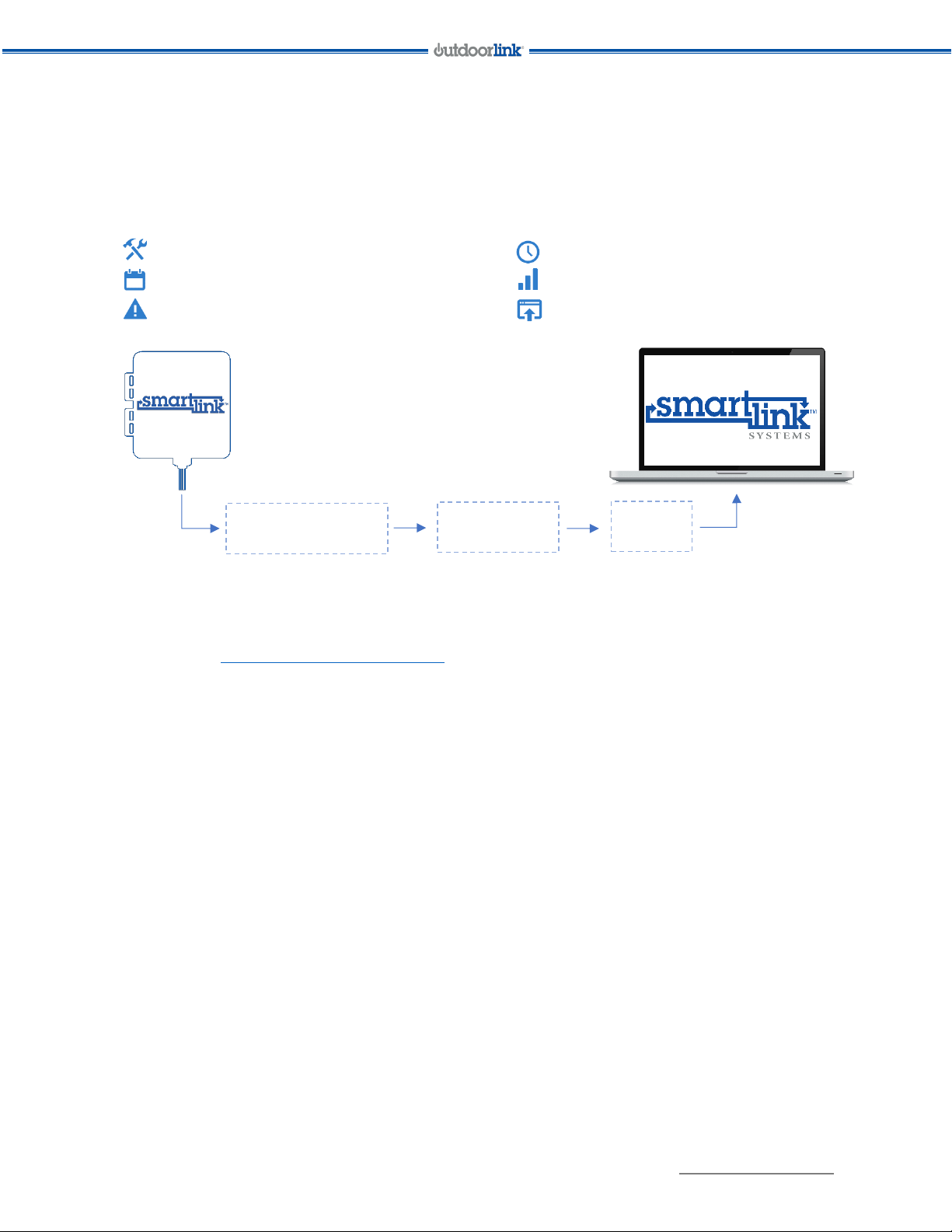
Planning Ahead
It is important to plan the installation so that the SmartLink™ unit is setup properly and that the
unit’s capabilities are maximized. Keep these items in mind as you plan the install:
•Two supply lines are needed to utilize all 4 relays of the unit: one for relays 1 and 2, and
the second one for relays 3 and 4.
•Individual relays are rated at 16A at 50C or 14A at 70C. Maximum load for a supply line
should not exceed 24A. Maximum load may be shared between relay sets (1+2 or 3+4)
as desired, such that neither specification is violated. For example, a relay 1 load of 16A
and a relay 2 load of 8A for a total of 24A.
•The SmartLink™ SL-4-AC-001/002 unit is designed for single phase 120V or 240V
operation and will not be able to meter power on relays 3 and 4 if multiphase power
such as 208V three phase (120V line to neutral) is used.
Electrical Service
The SmartLink unit is power by the 120V feed line servicing relays 1 and 2. A neutral return is
required for operation. Relays 3 and 4 are serviced by an additional feed line. Each of the relays
are independently fused.
Use of a single breaker is preferable for providing power to the SmartLink unit. This provides a
single cutoff point when servicing the unit.
Also, using a single breaker ensures that the power for all relays is provided by the same
voltage phase from the incoming utility service.
In order to control 240V fixtures two single phase 120V feed lines most be attached to the two-
unit inputs i.e., L1 and L2. Additionally, a relay from each of the two 120V feeds is required e.g.,
1 and 3 or 2 and 4.
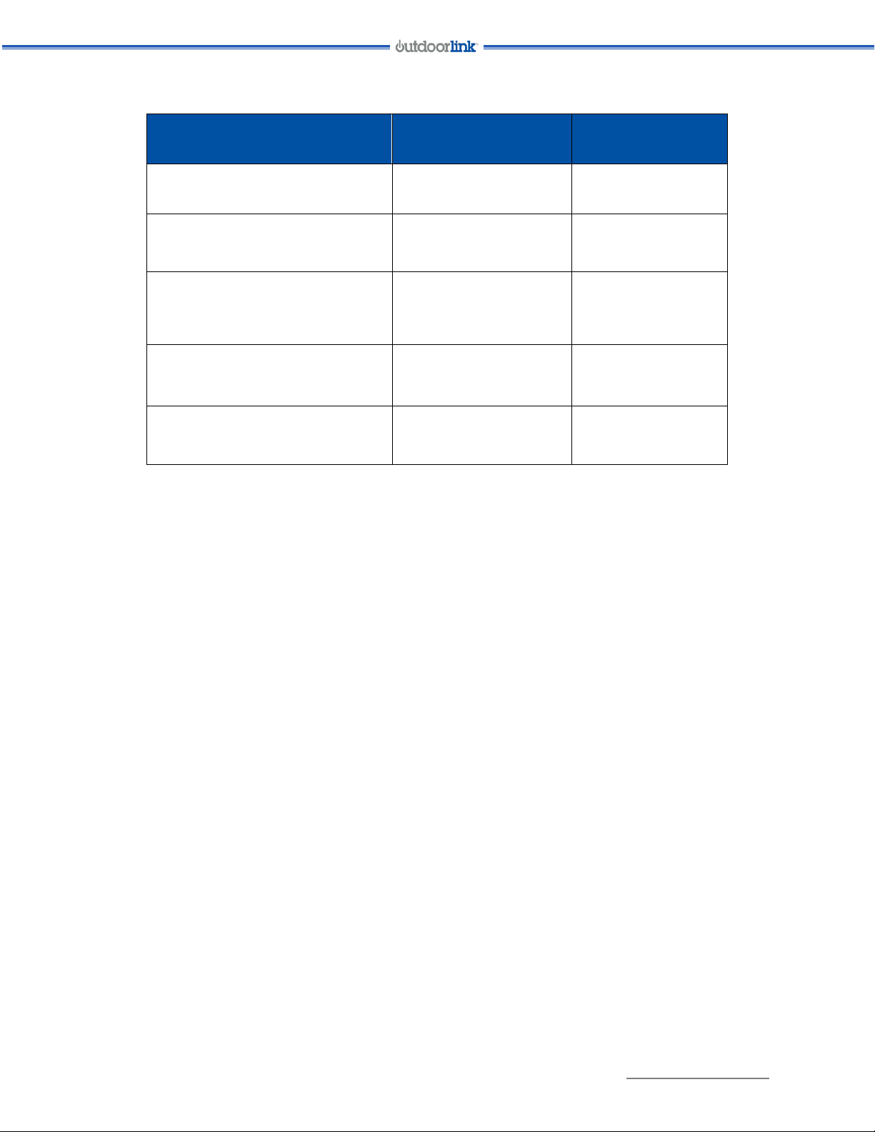
Table 1 provides a unit configuration chart as a recommendation for the install.