Oval EL4061 User manual

STEAM FLOW COMPUTER
MODEL : EL406
Ins. No. E-822-9-E
Every OVAL product is fabricated and shipped from our factory under stringent quality control. In order
to maintain its design performance throughout its life, this manual offers the operator the necessary
installation, operation and maintenance information.
Be well familiar with these instructions before you place the computer in service and keep this manual at
the eld location for ready reference.
We also recommended you to read the instruction manuals for the companion pulse generator (flowmeter)
and receiving instrument.

E-822-9-E
1. GENERAL .............................................................................................................................. 3
〈FEATURES〉........................................................................................................................ 3
2. PART NAMES......................................................................................................................... 3
3. OUTLINE DIMENSIONS ........................................................................................................ 3
4. INSTALLATION ...................................................................................................................... 4
4.1 Installation Location.........................................................................................................4
4.2 Mounting Panel................................................................................................................ 4
4.3 Installation Procedure......................................................................................................4
5. WIRING .................................................................................................................................. 5
5.1 Cables for Field Wiring ....................................................................................................5
5.2 Wiring Connections..........................................................................................................5
5.3 Terminal Block for External Connections ......................................................................... 5
6. OVERALL BLOCK DIAGRAM ................................................................................................ 6
7. CONVERSION FORMULA..................................................................................................... 6
8. CHANGING THE PULSE GENERATOR TYPE, METER SIZE (nominal bore),
METER ERROR, AND SCALER SETTINGS ......................................................................... 7
9. PULSE/ANALOG CONVERTER BOARD (OPTION) ............................................................. 8
10. OPERATION......................................................................................................................... 8
10.1 Preparation Before Operation........................................................................................ 8
10.2 Operation ....................................................................................................................... 8
11. TROUBLESHOOTING.......................................................................................................... 8
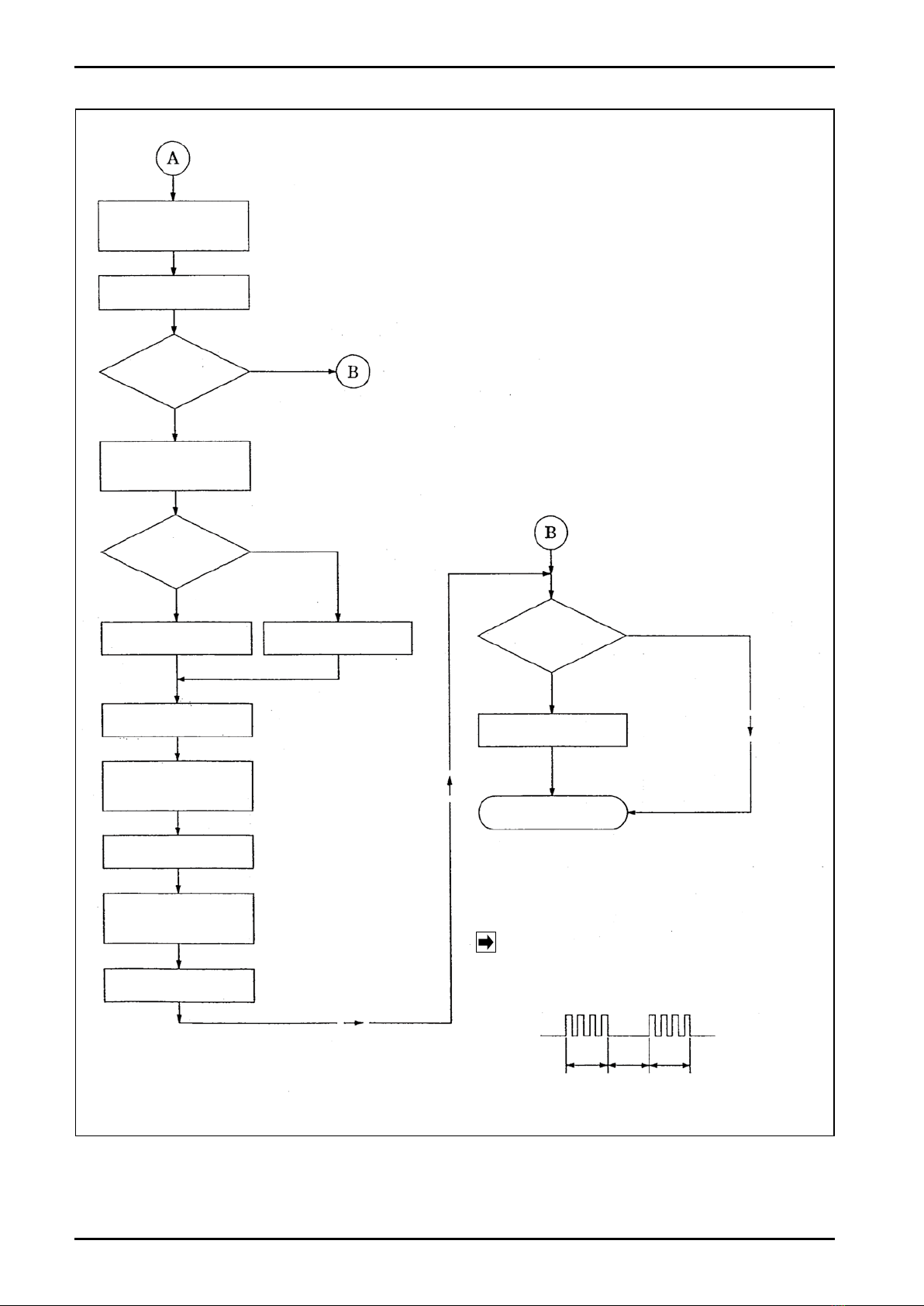
12. OPERATION FLOW CHART................................................................................................ 9
13. PRODUCT CODE EXPLANATION .................................................................................... 11
14. TOTAL COUNTER AND OUTPUT UNITS.......................................................................... 11
15. GENERAL SPECIFICATIONS............................................................................................ 12
CONTENTS
This manual uses the precaution words
"NOTE", "CAUTION", and "WARNING" as explained below:
NOTE:
Notes are separated from the general text to bring the user's
attention to important information.
CAUTION:
Caution statements inform the user of hazards or unsafe practices
which could result in minor personal injury or product/property
damage.
WARNING:
Warning statements inform the user of hazards or unsafe practices
which could result in severe personal injury or death.

E-822-9-E
1. GENERAL
Dedicated for steam service, this computer accepts signals from a steam service delta flowmeter. It
contains a microprocessor to perform steam pressure setting relative to service pressure, size (nominal
bore) setting and meter error adjustment, and indicates the total flow in terms of weight for accurate,
precise flow measurement.
〈FEATURES〉
(1)An inexpensive steam service computing totalizer for use with a steam service delta flowmeter.
(2)Simple pressure setting relative to the service pressure.
(3)Readily accepts size (nominal bore) alterations.
(4)A variety of self diagnostic features.
(5)Compatible with an instantaneous flow indicator (option).
2.PART NAMES
3.OUTLINE DIMENSIONS
OPERATIONINDICATOR
LED(RED)
7-DIGITTOTAL
COUNTER
UNITSOF
MEASURE
NAMEPLATE
PRESSURE
SETTING
SWITCH
UNITSOF
MEASURE,MPa
SEFT-TEST
BUTTON
TAGNO.NAMEPLATE
ENCLOSURE
MTG.FITTING
MODEL
NAMEPLATE
TERMINALSTRIP
(10P)
TERMINAL
IDENTIFICATION
POWERFUSE(0.5A)
PANEL1.6THICKMIN.
ENCLOSUREMTG.FITTING
(ONEEACHONTOPANDBOTTOM)
TERMINALSTRIP
75
150
10
180±1
201±1
11
Unit:mm
135
0
−1
67
0
−1
NOTE:1AFOR24VDCMODEL
Fig. 2.1
OPERATIONINDICATOR
LED(RED)
7-DIGITTOTAL
COUNTER
UNITSOF
MEASURE
NAMEPLATE
PRESSURE
SETTING
SWITCH
UNITSOF
MEASURE,MPa
SEFT-TEST
BUTTON
TAGNO.NAMEPLATE
ENCLOSURE
MTG.FITTING
MODEL
NAMEPLATE
TERMINALSTRIP
(10P)
TERMINAL
IDENTIFICATION
POWERFUSE(0.5A)
PANEL1.6THICKMIN.
ENCLOSUREMTG.FITTING
(ONEEACHONTOPANDBOTTOM)
TERMINALSTRIP
75
150
10
180±1
201±1
11
Unit:mm
135
0
−1
67
0
−1
NOTE:1AFOR24VDCMODEL
Fig. 3.1

E-822-9-E
4
4.INSTALLATION
4.1 Installation Location
Select an installation location where
(1)Mechanical vibration, shock and corrosive
gases least exist.
(2)Air is dry and temperature at room
temperature and stable.
NOTE: Although the manufacturer guar-
a n t e e s s t a t e d p e r f o r m a n c e a t
ambient temperatures up to 50 ℃, it
is recommended that the instrument
be placed in service at room temper-
ature.
(3)Provide a sufficient working space behind
the instrument - at least 50 centimeters from
the back of the instrument - to facilitate wiring
and maintenance.
4.2 Mounting Panel
(1)Use a rigid steel sheet with a minimum
thickness of 1.6 millimeters. Suggested
thickness is approximately 3.2 mm.
(2)If it is desired to mount instruments side by
side, dimensions in Fig.4.1 are suggested.
(3)Recommended mounting height ranges are
given in Fig.4.2.
4.3 Installation Procedure
(1)Front mount the steam flow computer through
the opening cut in the panel.
(2)Pass the enclosure mounting ttings furnished
through the holes at the bottom of the
enclosure and, con-rming that the instrument
is positioned on a level plane, secure the
instrument to the panel with the mounting
ttings (see Fig. 2).
Fig. 4.1 Panel Cutout
Fig. 4.2 Mounting Height
95min.
68−0.7
0
138 +1
0
200 min.
OPTIMUM
RANGE
ALLOWABLERANGE
600
1800
450
2200
95min.
68−0.7
0
138 +1
0
200 min.
OPTIMUM
RANGE
ALLOWABLERANGE
600
1800
450
2200
Unit:mm
Unit:mm

E-822-9-E
TERMINAL
STRIP
5. WIRING
5.1 Cables for Field Wiring
(1)Use electrostatically-shielded, polyethylene-insulated, vinyl-sheathed control cables, or equivalent,
for input signal cables (CEVS 1.25-2.00mm2, 2-conductor). For signal cables, vinyl-insulated, vinyl-
sheathed cables (CVV, CVS, JIS C 3401) are recommended.
(2)Ground the cable shielding to terminal "G" of the instrument. All circuitry on the detector side must
be "floated" from ground.
CAUTION
Make electrical connections upon
confirmation of valid combinations
of flowmeter (pulse generator) and
receiving instrument by their model
No., serial No., etc.
Fig. 5.1 Terminal Strip
(2)Separate field wiring from other power lines and power circuits to minimize the possibility of
inductive interference.
(3)Using crimp-style terminals for wiring connections, ensure good electrical connections. Terminals
are found on the back of the computer.
(4)Good practice is to provide an allowance of 30 centimeters approx. to the wirings to facilitate
internal assembly withdrawal during servicing.
5.2 Wiring Connections
(1)Conduit work is recommended for eld wiring.
NOTE: In conduit work, use separate conduit for power cable and signal cables to eliminate the
possibility of stray current pickup.
NAME TERMINAL No. DESCRIPTION
Power 9 (hot)
10 (neut) 100V, 110V/115V, 200V, 220V/230V AC, 50/60Hz
Ground 8 Earth ground terminal
Flow Input PA15, 25 1, 2 1:+ 24V,2:SIG
Weight Output 4, 5 4 ( +), Width 5 ( -), Open collector output
Width:1 to 4ms(reduction 1/1), 40 to 60ms(reduction 1/10 or 1/100)
Weight Analog Output * 6, 7 6 ( +), 7( -) 0 to 100 μA, 0 to 10mA
4 to 20mA, 10 to 50mA, 1 to 5V DC
5.3 Terminal Block for External Connections
NOTE *: Analog output is option.

E-822-9-E
6
POWERSOURCE
POWERTOPULSE
GENERATOR
FLOWRATE
PULSEINPUT
WEIGHT
ANALOGOUTPUT
WEIGHT
PULSEOUTPUT
0.5Aor1A
24V
5V
POWER
SUPPLY
CURRENTLIMIT
ANDOVERCURRENT
DETECTORCIRCUIT
WAVESHAPING
F/ICONVERTER
CIRCUIT
(OPTION)
ONE-SHOTMULT.
OUTPUTCKT.
CHECK/RUN
CONTROLCKT.
FREQ.DIVISION
SELECTOR
1/1,1/10,1/100
INSTANTANEOUSPOWER
INTERRUPTIONDETECTOR
ANDPOWERRESETCKT.
METERERROR,FREQ.
DIVISION.APPLICABLE
STANDARDSETING
JUMPERS
INTERRUPTCKT.
SETTINGRANGE
0.00to1.99MPa
PRESSURE
SETTING
SWITCH
7-DIGIT
TOTAL
COUNTER
LED
TEST
CHECK/RUN
SELECT
SWITCH
(FRONTPANEL)
SIZE(NOM.DIA.)
SETTING
SWITCH
ONE-SHOTMULT.
CIRCUIT
SINGLE-CHIPMICROPROCESSOR
6.OVERALL BLOCK DIAGRAM
Fig. 6.1
7.CONVERSION FORMULA
In response to the incoming flowrate signal from a delta meter, the computer performs weight conversion
of saturated steam according to the setpoints established on the front panel preset switches.
(Input pulse factor)×(Specic weight)×ε t
〈Conversion Formula〉=
(Output unit)
εt=1+3α(t-20)
where t : Temperature
3α:4.8×10⁻⁵(stainless steel)
The specic weight is thus determined in approximation as a function of the second degree.

E-822-9-E
8.CHANGING THE PULSE GENERATOR TYPE, SIZE (nominal bore),
METER FRROR, AND SCALER SETTINGS
(They are correctly set in the factory before shipment and normally require no further alterations.)
(1)Input Settings Relative to Pulse Generator Type
(2)Selection of Size (nominal bore)
With S4 (hexadecimal rotary switch). set up the value which agrees with the meter size, referring to
the table below.
Flowmeter Pulse Generator Type
R1 R4
R21 J
8
(jumper)
Preamplier PA15 or 25 Eliminated 240 Ω、1W 39 Ω、1/4W Shorted
(3)Selection of Meter Error
A compensation range of ±7.5% is covered with jumper J1in increments of 0.5%.
Rotary Switch Nominal Size,
mm
Nominal Meter
Factor Rotary Switch Nominal Size,
mm
Nominal Meter
Factor
0 15 0.005338 8 50 ②0.1001
1— — 9— —
2 25 ①0.01613 A 80 0.3328
3 25 ②0.01650 B 100 0.7567
4— — C 150 2.422
5 40 ①0.04363 D 200 7.021
6 40 ②0.04556 E 250 13.54
7 50 ①0.09655 F 300 23.24
NOTE: Separate rotary switch positions are allocated because positions 2 and 3; 5 and 6; 7 and 8
have different nominal meter factors.
(4)Selection of Scaler Setting (for total counter)
J2(jumper): Open →1/100; shorted →1/10
NOTE: In totalizer scaler setting, a 1/10 scale may, under certain conditions, not be available
depending on given operating conditions.
For details, see Section "13. Total Counter and Output Units".
(5)Power Source Selection
(6)Selection of Scaler Setting (for pulse output)
(7)Miscellaneous
In the standard specication, J9through J12 are shorted out across "1-C".
Power Source
J3J4J5
J
6
J
7
100V AC, 50/60Hz C-2 Open Open Shorted Shorted
110/115V AC, 50/60Hz C-1 Open Shorted Open Shorted
200V AC, 50/60Hz C-2 C-1 Open Open Open
220/230V AC, 50/60Hz C-1 C-2 Open Open Open
Frequency Division J
13
J
14
Output Width
1/1 C-10 C-1 1 to 4 ms
1/10 C-10 C-2 40 to 60 ms
1/100 C-100 C-2 40 to 60 ms

E-822-9-E
9.PULSE/ANALOG CONVERTER BOARD (OPTION)
An F/I converter board to provide an analog output proportional to the pulse frequency after weight
conversion may be added as an option.
(1)0 to 100 μA or 0 to 10mV output
★ Output adjustment is made with VRI.
(2)In cases of 4 to 20mA, 10 to 50mA or 1 to 5V output
10.OPERATION
10.1 Preparation Before Operation
(1)Inspect that your instrument and related equipment are correctly installed and wired with no points
left unnished (including size, meter error and frequency division settings).
WARNING: Make sure to see that the power terminals are connected to a
power source of the rated voltage. Applying a power source of
incorrect voltage could ruin your instrument.
(2)Preoperational Checks
Check to see whether or not the computer registers counts with no flow.
(3)How to Check
①
Turn on power and make sure that the front panel LED lights at intervals of two or three seconds.
② Depress the CHECK button and confirm individual settings in the CHECK mode.
(CHECK mode operation is described on Sec.12.)
10.2 Operation
(1)Turning on power
The LED will light up about a second later and stays on for about two seconds before the RUN mode is indicated.
(2)Allow steam to flow to initiate service operation.
11.TROUBLESHOOTING
Output J9J10
4 to 20 mA 2 -C 2 -C
10 to 50 mA 2 -C 2 -C
1 to 5 V 1 -C 1 -C
SYMPTOM CHECK POSSIBLE CAUSES
1. The LED fails to come on.
1. Inspect fuse.
2. Make sure of power source
voltage.
1. Fuse is blown.
2. Line voltage is improper.
3. A fault in internal power supply.
2. The LED shows RUN mode but
fails to count incoming pulses.
1. Input signal lines.
2. Signal coming in?
1. Incorrect input wiring.
2. Flowmeter preamlier is at fault.
3. A fault in the input circuitry.
3. The LED indicates a fault in the
probe. 1. Input signal lines. 1. Incorrect input wiring.
2. Flowmeter preamplier is at fault.
4. Erratic accumulated total
reading.
1. Size (nominal dia.) and pressure
settings (see "CHECK Mode"). 1. A fault in the internal assembly.
If the trouble is suspected to be internal to the steam ow computer, seek our service.
NOTE: J9 and J10 are jumpers on the computing board.
Fine output adjustment is made with VR2 (zero adjust) and VRI (span adjust).

E-822-9-E
RUNMODEFLOWCHART
RUNMODE
Sizesetting
correct?
YES
Pressure
changed?
NO
NO
LEDlightsat
intervalsof
2sec.
Sensor
faulty.
YES
YES
LEDlightsat
intervals.of
2sec.
LEDblinksat
intervalsof
onesec.
LEDlights0.5
sec.:goesout
0.5sec.
itrepeatsthis
cycling.
※
Inputpulses
areunacceptable
atthistime.
LEDblinksfast
for2sec.
LEDblinks
forpresetnumber.
LEDlights
for0.5sec.
LEDblinks
forpresetnumber.
LEDlights
for0.5sec.
LEDblinks
forpresetnumber.
LEDlights
for0.5sec.
Press.setting
onel.h.digit
(0,1).
Press.setting
onecenter
digit(0to9).
Press.setting
ldigitatR.H.
end(0to9).
CHECKMODEFLOWCHART
CHECKMODE
LEDblinks
for2sec.
Totalcounter
counts3pulses;
LEDlightsin
synchronism.
LEDblinks
for2sec.
LEDlightsforpre-
setnumberatin-
tervalsof0.5sec.
LEDlights
for0.5sec.
LEDlightsforpre-
setnumberatin-
tervalsof0.5sec.
LEDlights
for0.5sec.
LEDlightsforpre-
setnumberatin-
tervalsof0.5sec.
LEDlightsfor
0.5sec.
LEDblinks
foronesec.
Sizesetting
correct?
Showsthe
checkmode.
Checksinput
andoutput
circuitswitha
simulatedpulse
train(1hZ).
Showspressure
settingbeing
reviewed.
Press.setting
onel.h.digit
(0,1).
Divisionby
decimalpoint
Press.setting
onecenter
digit(0to9).
Press.setting
1digitatR.H.
end(0to9).
Showssize
beingreviewed.
LEDblinksonand
offatintervals
of0.5sec.
Size(nom.dia.)set
correctlyornot
NO
NO
YES
12.OPERATION FLOW CHART

E-822-9-E
0
LEDlightsforthe
presetnumberat
intervalsof0.5sec.
LEDlights
for0.5sec.
Metererror
set?
LEDblinkstwice
forasecond.
Positive
correction?
LEDlightstwice.
LEDlights
for0.5sec.
LEDlightsforthe
presetnumberat
intervalsof0.5sec.
LEDlights
for0.5sec.
LEDlightsforthe
presetnumberat
intervalsof0.5sec.
LEDlights
for0.5sec.
MeterSizeisshownininches:
Indicatestherotaryswitchpositioncurrentlysetup.
PostitionsA,B,C,D,E,andFareindicatedbyblinking
10,11,12,13,14,and15times,respectively.
NO
NO
YES
YES
Metererror
setornot
Showswhetherpositive
correctionornegative
correction.
LEDlightsonce.
Showsthefirstdigitof
thefigureinpercent(0to3).
Showsthelastdigitof
thefigureinpercent(0to5).
Freq.division
set?
LEDlightsfor2sec.
RUNMODE
1/10Freq.division
setornot
NO(1/100)
YES(1/10)
①Incomingpulsesareunaccept-
ablewhilemakingacheck.
②Blinkpatternisshownbelow.
EXAMPLE:Intervalsatonesecond
NOTE:
1sec. 1sec. 1sec.
LIGHTS LIGHTS
GOES
OUT

E-822-9-E
13.TOTAL COUNTER AND OUTPUT UNITS
NOTES: ※1:Because the max. frequency the magnetic counter can respond is 5Hz, it is necessary
that a requirement Max. flowrate[kg/h]
3600 ×Totalizer unit[kg]≦5[Hz]be satised.
Hence, a 1/10 scale may, under certain conditions, not be available depending on
given operating conditions.
※2:Provided with remote instantaneous flowrate output.
Delta Flowmeter
Nominal Diameter
Totalizer
Least Signicant Digit, kg
Open Collector Mass Pulse Output
kg
Analog Output
Min, Full Scale
Flowrate,kg/h ※2mm Scaling 1/10 ※1 1/100 1/1 1/10 1/100
15 0.01 0.1 0.001 0.01 0.1 15
25 0.01 0.1 0.001 0.01 0.1 15
40 0.1 1 0.01 0.1 1 150
50 0.1 1 0.01 0.1 1 150
80 1 10 0.1 1 10 1500
100 1 10 0.1 1 10 1500
150 1 10 0.1 1 10 1500
200 10 100 1 10 100 15000
250 10 100 1 10 100 15000
300 10 100 1 10 100 15000
ITEM DESCRIPTION
Input
Pulse Generator
Delta meter preamplier PA15 or 25
Signal Levels "1": 20mA min.; "0": 4mA max.
Overcurrent Detection
PA15 and 25: An erratic probe is indicated above 27 ±4mA (LED flickers).
Pressure Front-panel digital switch establishes the operating pressure
(0.00 to 1.99MPa in 0.01MPa steps).
Meter Size (nominal
bore)
Internal rotary switch establishes value which agrees with meter size.
For rotary switch positions, see Section 8.(2) "Setting of Meter Size (nominal bore)."
Meter Error Internal jumper establishes corrections (in a range of from 0.0 to ±7.5% in 0.5% steps).
Scaling (totalizer) Internal jumper establishes the factor of frequency reduction (1/10 or 1/100).
Scaling (Output) Internal jumper establishes the factor of frequency division (1/1 or 1/10 or 1/100).
Pulse Output after Conversion
in Terms of Mass
Open collector max. rating: 30V DC, 0.1A
Pulse width: 1-4ms., 40-60ms. (with 1/10 or 1/100 reduction)
Analog Output after
Conversion in Terms of Mass
An analog output of instantaneous flowrate in terms of mass (option)
Accumulated Total Display
7-digit electromagnetic counter
Seft-Test Function ±0.3% of reading
Computing Accuracy Depressing the self-test button advances the reading by 3 counts when functioning correctly.
Power Supply 100, 110/115, 200, 220/230V AC, 50/60Hz
Power Consumption 7VA max.
Ambient Temperature -10℃to +50℃
Insulation Resistance
Across power terminals bundled and ground terminal: Greater than 10M Ωwith 500V DC Megger
Withstand Voltage Across power terminals bundled and ground terminal: 1500V AC for one minute
Installation Panel mount
Finish Instrument frame (resin molding): Munsell N1.5
Enclosure (steel sheet): Munsell N6.0
Mass 1 kilogram approx.
14.GENERAL SPECIFICATIONS

E-822-9-E
⑧−⑥⑤④③②① ⑯⑮⑭⑬⑫⑪−⑨ ⑰ −⑳⑲⑱ ㉒
Model
Powersupply
Inputsignal
AlwaysN
Outputitem2
Outputitem3
AlwaysN
Versioncode
Characteristic
AlwaysN
Outputitem1
Maincode
/ / /Additionalcode
15.GENERAL SPECIFICATIONS
●
Main code
①②③④⑤⑥Model
E L 4 0 6 1 Steam Flow Computer
⑦—
⑧Power supply
E100VAC 50/60Hz
F110/115VAC 50/60Hz
G200VAC 50/60Hz
H220/230VAC 50/60Hz
⑨Input signal
DCurrent pulse 24VDC (4/20mA)
ZSpecial
⑩—
⑪ ⑫ Output item 1
Pulse output
B 1 Pulse width 1 to 4ms
B 5 Pulse width 40 to 60ms
B 9 Pulse width other than above
⑬Always N
N Always "N"
⑭ ⑮ Output item 2
Pulse output
N N None
⑯Always N
N Always "N"
⑰ ⑱ Output item 3
Analog output
N N None
A 2 1 to 5V
A 5 4 to 20mA
A P 0 to 10mV
A Q 10 to 50mV
A R 0 to 100μA
Z Z Special
⑲Always N
N Always "N"
⑳Version code
A Version A
—
Characteristic
0Standard
ZSpecial
Document
D S J Delivery specication (Japanese)
D S E Delivery specication (English)
D R 0 Re-submission of Delivery specication
D C J Final DWG (Japanese)
D C E Final DWG (English)
D W J Wiring diagram (Japanese)
D W E Wiring diagram (English)
D T J Inspection procedure (Japanese)
D T E Inspection procedure (English)
C B J Inspection certicate: B set Only Japanese
Witnessed by customer
V 1 0 Required
●
Additional code

E-822-9-E
Item Code No. SUPPLEMENT. CODE DESCRIPTION
①②③④⑤⑥-⑦⑧⑨⑩⑪⑫
Model E L 4 0 6 1 -Steam Flow Computer
Power
1 100V AC 50/60Hz
2 200V AC 50/60Hz
3 110/115V AC 50/60Hz
4 220/230V AC 50/60Hz
9 Other than above
Input 4 Preamplier PA15 or 25
9 Other than above
0 Always "0"
Analog Output
0 None
1 F/I converter output provided(1 to 5V)
2 F/I converter output provided(0 to 10mV)
4 F/I converter output provided(4 to 20mA)
5 F/I converter output provided(10 to 50mA)
7 F/I converter output provided(0 to 100μA)
9 Other than above
1 Always "1"
Instrument Frame Color 1 Munsell N1.5
《PRODUCT CODE EXPLANATION OF THE OLD PRODUCT CODE》
The new product code has been implemented since April 2017.
Therefore, the product code explanation of the old product code will not be updated after April 2017.
Contact OVAL if you wish to order with the old product code for reasons such as type approval.

E-822-9-E
All specifications are subject to change without notice for improvement.
2019.04 Revised △
E-822-9-E (1)
Table of contents
Other Oval Desktop manuals
Popular Desktop manuals by other brands

Acer
Acer Aspire L310 Manuel d'utilisation

Compaq
Compaq Compaq Pro 6305 Hardware reference guide

Shuttle
Shuttle xxpc Barbone SG45H7 Product specifications

HP
HP EliteDesk 705 G4 Maintenance and service guide

Advantech
Advantech TREK-688 user manual

Asus
Asus RS700-E6 - 1U Rm Bb Tylesburg 36D Xeon-dp 4XSATA... Configuration guide