Oval NPI45 Series User manual

Microswitches
+
Potentiometer provided
Direct-reading type
Microswitch provided
or
Potentiometerv provided
This manual has been prepared to provide you with the information pertinent to the VALVE POSITION
INDICATOR. With the proper application of the information and knowledge contained in this manual, you will
be able to expect the best possible results over a long service life of this instrument. Keep this manual at hand
for your quick reference.
OVAL VALVE POSITION INDICATOR
MODEL NPI 45

CONTENTS
1. BEFORE YOU BEGIN ・・・・・・・・・・・・・・・・・・・・・・・・・・・・・・・・・・・・・・・・・・・・・・・・・・・・・・・・・・・・・・・・・・・・・・・・・・ 3
1.1 Transportation Considerations ・・・・・・・・・・・・・・・・・・・・・・・・・・・・・・・・・・・・・・・・・・・・・・・・・・・・・・・・・・・・・ 3
1.2 Storage Considerations ・・・・・・・・・・・・・・・・・・・・・・・・・・・・・・・・・・・・・・・・・・・・・・・・・・・・・・・・・・・・・・・・・・・・ 3
2. OPERATING CONDITIONS ・・・・・・・・・・・・・・・・・・・・・・・・・・・・・・・・・・・・・・・・・・・・・・・・・・・・・・・・・・・・・・・・・・・・・ 3
3. GENERAL ・・・・・・・・・・・・・・・・・・・・・・・・・・・・・・・・・・・・・・・・・・・・・・・・・・・・・・・・・・・・・・・・・・・・・・・・・・・・・・・・・・・ 4
3.1 General ・・・・・・・・・・・・・・・・・・・・・・・・・・・・・・・・・・・・・・・・・・・・・・・・・・・・・・・・・・・・・・・・・・・・・・・・・・・・・・・・・・ 4
3.2 Part Names ・・・・・・・・・・・・・・・・・・・・・・・・・・・・・・・・・・・・・・・・・・・・・・・・・・・・・・・・・・・・・・・・・・・・・・・・・・・・・・ 4
3.3 General Specications ・・・・・・・・・・・・・・・・・・・・・・・・・・・・・・・・・・・・・・・・・・・・・・・・・・・・・・・・・・・・・・・・・・・・・ 5
3.4 Product Code Explanation ・・・・・・・・・・・・・・・・・・・・・・・・・・・・・・・・・・・・・・・・・・・・・・・・・・・・・・・・・・・・・・・・・ 5
4. CONFIGURATION AND OPERATING PRINCIPLE ・・・・・・・・・・・・・・・・・・・・・・・・・・・・・・・・・・・・・・・・・・・・・・・・・・・・・ 7
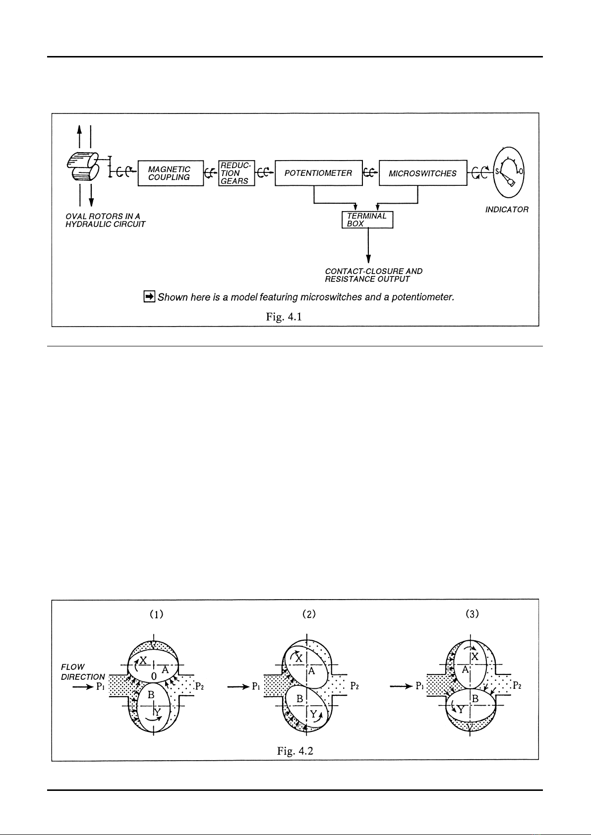
4.1 Conguration ・・・・・・・・・・・・・・・・・・・・・・・・・・・・・・・・・・・・・・・・・・・・・・・・・・・・・・・・・・・・・・・・・・・・・・・・・・・・ 7
4.2 Operating Principle ・・・・・・・・・・・・・・・・・・・・・・・・・・・・・・・・・・・・・・・・・・・・・・・・・・・・・・・・・・・・・・・・・・・・・・・ 7
5. MICROSWITCH AND POTENTIOMETER OPERATION DIAGRAMS ・・・・・・・・・・・・・・・・・・・・・・・・・・・・・・・・・・・・・・ 8
6. WIRING CONNECTIONS ・・・・・・・・・・・・・・・・・・・・・・・・・・・・・・・・・・・・・・・・・・・・・・・・・・・・・・・・・・・・・・・・・・・・・・・・ 9
6.1 Field Wiring ・・・・・・・・・・・・・・・・・・・・・・・・・・・・・・・・・・・・・・・・・・・・・・・・・・・・・・・・・・・・・・・・・・・・・・・・・・・・・・ 9
6.2 Terminal Arrangement ・・・・・・・・・・・・・・・・・・・・・・・・・・・・・・・・・・・・・・・・・・・・・・・・・・・・・・・・・・・・・・・・・・・・ 9
6.3 Connections at Terminals ・・・・・・・・・・・・・・・・・・・・・・・・・・・・・・・・・・・・・・・・・・・・・・・・・・・・・・・・・・・・・・・・・・・ 10
7. OPERATING PRECAUTIONS ・・・・・・・・・・・・・・・・・・・・・・・・・・・・・・・・・・・・・・・・・・・・・・・・・・・・・・・・・・・・・・・・・・・・・・ 12
8. MAINTENANCE ・・・・・・・・・・・・・・・・・・・・・・・・・・・・・・・・・・・・・・・・・・・・・・・・・・・・・・・・・・・・・・・・・・・・・・・・・・・・・・・・ 13
9. DISASSEMBLY AND INSPECTION ・・・・・・・・・・・・・・・・・・・・・・・・・・・・・・・・・・・・・・・・・・・・・・・・・・・・・・・・・・・・・・・・・ 16
9.1 Basic Body (wetted parts) Disassembly and Inspection ・・・・・・・・・・・・・・・・・・・・・・・・・・・・・・・・・・・・・・・・・ 16
9.2 Magnetic Coupling Disassembly and Inspection ・・・・・・・・・・・・・・・・・・・・・・・・・・・・・・・・・・・・・・・・・・・・・・・ 17
9.3 Reduction Gear Train Disassembly and Inspection ・・・・・・・・・・・・・・・・・・・・・・・・・・・・・・・・・・・・・・・・・・・・・ 18
9.4 Assembly Procedure ・・・・・・・・・・・・・・・・・・・・・・・・・・・・・・・・・・・・・・・・・・・・・・・・・・・・・・・・・・・・・・・・・・・・・・・ 19
10. MICROSWITCH, POTENTIOMETER, AND FRICTION CLUTCH ARRANGEMENTS ・・・・・・・・・・・・・・・・・・・・・・・・・ 20
10.1 Direct-reading Type and Microswitch Equipped Model ・・・・・・・・・・・・・・・・・・・・・・・・・・・・・・・・・・・・・・・・・ 20
10.2 Potentiometer Equipped Model ・・・・・・・・・・・・・・・・・・・・・・・・・・・・・・・・・・・・・・・・・・・・・・・・・・・・・・・・・・・・・ 20
11. ASSEMBLY DRAWINGS AND PARTS LIST ・・・・・・・・・・・・・・・・・・・・・・・・・・・・・・・・・・・・・・・・・・・・・・・・・・・・・・・・・ 21
11.1 MODEL NPI45B00 Assembly Drawing and Parts List ・・・・・・・・・・・・・・・・・・・・・・・・・・・・・・・・・・・・・・・・・・・・ 21
11.2 Model NPI45B10 Assembly Drawing and Parts List ・・・・・・・・・・・・・・・・・・・・・・・・・・・・・・・・・・・・・・・・・・・・・ 22
11.3 Model NPI45B20 Assembly Drawing and Parts List ・・・・・・・・・・・・・・・・・・・・・・・・・・・・・・・・・・・・・・・・・・・・・ 23
11.4 Model NPI45B30 Assembly Drawing and Parts List ・・・・・・・・・・・・・・・・・・・・・・・・・・・・・・・・・・・・・・・・・・・・・ 24
12. OUTLINE DIMENSIONS ・・・・・・・・・・・・・・・・・・・・・・・・・・・・・・・・・・・・・・・・・・・・・・・・・・・・・・・・・・・・・・・・・・・・・・・・・ 25
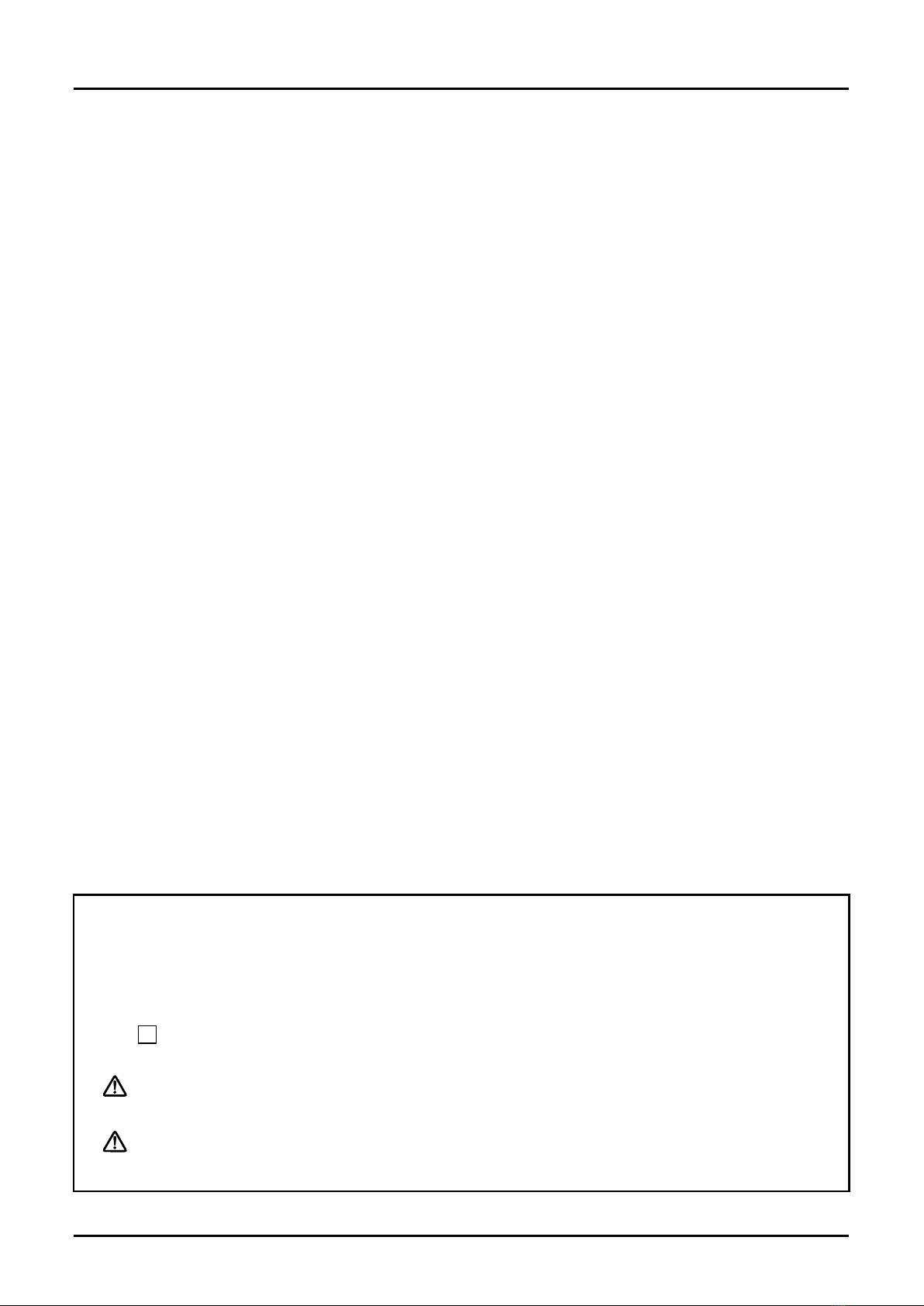
CONVENTIONS
Shown in this manual are the signal words , and , as described in the
examples below:
Notes are separated from the general text to bring the user’s attention to
important information.
Caution statements signal the user about hazards or unsafe practices which could
result in minor personal injury or product or property damage.
Warning statements signal the user about hazards or unsafe practices which
could result in severe personal injury or death.
➡➡

Every OVAL Valve Position Indicator is thoroughly tested before it leaves the factory. When received, it should
thoroughly be inspected for indication of rough handling during transit. Necessary handling precautions are
described in this section; read the instructions carefully.
For any inquiries, contact your nearest OVAL designated sales oce.
(1) To safeguard against damage during transit, transport the OVAL Valve Position Indicator to the
installation site in the same container used for transportation from the factory if circumstances permit.
(2) OVAL Valve Position Indicator is adjusted and inspected as an assembly consisting of the meter body,
sensor, pulse generator, etc. It should therefore be handled as an integral assembly.
(3) The register is accurately congured and adjusted. Do not remove its front cover to gain access to its
internal assembly except for reconguration.
If your OVAL Valve Position Indicator is stored for long periods of time upon receipt before installation,
unexpected faulty conditions could result. If a long-term storage is anticipated, take the following precautions:
(1) Keep the OVAL Valve Position Indicator in store in the same shipping container used for transportation
from OVAL if possible.
(2) Place of storage should conform to the following requirements:
★ Free from rain and water.
★ Free from vibration and impact shocks.
★ Temperature and relative humidity in the storage place are at or near room temperature and humidity
(around 25℃ and 65%).
(3) Purge the OVAL Valve Position Indicator that has once been placed in service with clean air, N2 gas, etc.
to prevent the metered uid from adhering to the meter connections, piping inner walls, housing, etc.
before storage. (Wash clean with suitable detergent if necessary.)
Wash with clean detergent or cleansing uid if necessary.
(4) If storage for extended periods of time is anticipated, good practice is to keep the product in store in the
original conditions at shipment.
To maintain the stated high accuracy and long service life of the OVAL Valve Position Indicator, make sure that
flowrate, pressure, temperature and viscosity are held within the specified. These operating conditions are
stated in the GENERAL SPECIFICATIONS on page 5.
➡➡

In a hydraulic control system for remotely controlling
a valve, it is essential that the position of the valve
be exactly detected for satisfactory operation of the
entire system. Specically designed and built for this
purpose is the OVAL Valve Position Indicator
(owmeter), which, connected in the actuator line of
the valve (a buttery valve, for example), enables the
operator to learn the operating status of the valve at
a glance by detecting the quantity of hydraulic oil
which has been transferred from time to time.
Containing an integral potentiometer and
microswitches, this lightweight and compactly built
OVAL Valve Position Indicator (flowmeter) offers
electrical signal transmission to a remotely located
point.
(1) Remote readout capability makes this indicator best suited for a centralized supervisory system.
(2) Easy to maintain with simple, sturdy and compact design.
(3) Positive displacement type owmeter (OVAL gears) oers outstanding metering accuracy and reliability.
(4) Owing to integral microswitches and potentiometer, the system designer can build a wide choice of
control systems with ease.
(5) The pointer comes into contact with the stopper at 97 to 100% of valve actuator capacity and the
remaining 0 to 3% capacity is absorbed by the slip friction clutch. Therefore, the pointer position is
automatically corrected each time the valve is opened or shut.

① ② ③ ④ ⑤ ⑥ ⑦ ⑧ DESCRlPTlON
Model N P I Valve Position Indicator
Meter Size 4 5 Max.owrate 8 L/min.
Pressure (meter body material) B 13.7MPa(Meter body material: FC250)
Transmitter
and Connector
0 Direct-reading type
1 Two microswitches with connector provided
2 Potentiometer provided
3 A potentiometer and two microswitches provided
9 Other than above
Connections
0 Standard (φ6)
1 O-ring grooved (φ6-P18)
2 Rc connection (Rc 3/8)
9 Other than above
Model Flow Range, L/min (L/h) Applicable Cylinder
Capacity (L)
NPI45 0.083 to 8 (5 to 480) 0.05 to 10
Item Description
Indicating Accuracy 0 to +3% (Accuracy as a owmeter ±0.3%)
(The pointer full span at 97 to 100% of applicable cylinder capacity.)
Max. Operating Pressure Standard type 13.7MPa
Operating Temperature Range -10 to 80℃
Process Connection
Nominal Diameter
Specication Connection
Standard φ6
O-ring grooved Fits φ6-P18
Rc screw Pc3/8
Flow Direction Left and right. Left to right causes the pointer to move clockwise.
Acceptable Fluid Hydraulic oil ISO VG32, 56 or equiv.
Indicator Eccentric. Pointer deection angle 128.3°
Finish A single coat of primer sprayed (reddish brown)
Materials of Major Component
Parts
Pressuretight body: FC250
Rotors: Sintered Fe
Indicator housing: Plasting (polycarbonate resin)
NOTE: For explosionproof construction models, consult factory.➡➡

Built-in microswitches and potentiometer detect the positions of a valve, or other device, and the obtained
information is transmitted in the form of electrical signal to a remotely located supervisory control room, etc.
Microswitch Potentiometer
Functions Transmits only the open or shut status as a
contact closure signal.
Transmits the valve position as a resistance
value.
Electrical
Specications
Ratings (resistive load): 250VAC,1A
30VDC,1A
Power rating: 1W at 70℃
Standard resistance: 1kΩ /340℃
Ambient temperature range:
25 to +85℃
Accuracy of resistance value: ±20%
Linearity of potentiometer alone: ±1%
Ambient temp. range: -40 to +100℃

(1) Two Oval rotors are used in the wetted measuring chamber in contact with the fluid as shown in the
diagram below. Assume that the inlet pressure is P1 and the outlet pressure P2. Pressure P1 is uniformly
distributed over the entire teeth on its side P1; no torque acts on rotor B. Regarding rotor A, on the other
hand, pressures P1 and P2 act on its inlet tooth area (area “a”) and its outlet area (area “a”), respectively,
separated at a parting point “0” at which the two rotors mesh. Since their pressure relationship is P1>P2,
the resulting rotational dierential force represented by a・P1>a・P2 acts on rotor A, forcing it to turn in the
arrow direction “X.” At a 90° displaced position, then, rotors A and B alternate places with each other; rotor
B is forced to turn in the arrow direction “Y.” This motion continues without coming across a dead point as
long as the process ow is maintained.
(2) Liquid is precisely quantied by a crescent-shaped cavity (V) formed by the chamber wall and Oval rotors.
The amount (q) of uid carried in every rotation of the Oval rotor is four times the crescent-shaped pocket
“V.”
(3) This turning eort of Oval rotors is transmitted to the indicator through a magnetic coupling, reduction
gear train, and potentiometer/microswitch arrangement. The volume of uid passing across the measuring
chamber is determined in this way, allowing the valve position to be displayed on the indicator.


With a model equipped with connectors (terminal block), make wiring connections in accordance with the
procedure given below:
Use cables conforming to the following specications for eld wiring unless otherwise specied:
Standard polyethylene-insulated cable 0.3mm2 in conductor area
The maximum signal transmission length is one kilometer.
NOTE: If it exceeds one kilometer, consult the factory.
To prevent possibility of stray current pickup, route the field wiring sufficiently away from existing power
cables and power circuits.
NOTE: All circuits below are shown in the totally closed position.
➡➡
➡➡

Remove the connector of the instrument and make connections of lead wires to its internal assembly (terminal
block).
(1) Using screwdriver, loosen the screw securing the
connector, extract the connector, and separate
from the bracket (Fig. 6.2).
NOTE: The bracket is coupled to the connector
with male/female connector.
(2) Holding the connector in your hand with its
internal assembly (terminal block) up, extract the
internal assembly by inserting the blade of
screwdriver into the lift clearance and prying o
as shown in Fig. 6.3.
(3) With connector tting screw, washer, and rubber
packing removed, pass them onto the cable, pass
the cable into the connector cover and pull it out
toward the terminal block. Rubber packing has
concentric cuts for adjustment: cut to the O.D. of
the cable used (Fig. 6.4).
(4) Separate three conductors of the cable, remove
insulation 7 mm approx. from individual
conductors, pass into respective screw slots on
the terminal block, and tighten with screw
securely (Fig. 6.5).
To ensure good electrical connections, we
recommend to tin lead wire ends.
(5) Install the wired terminal block into the
connector cover and secure it by forcing into
place until the lock boss of terminal block snaps
into position.
➡➡

NOTE: While installing the terminal block into the cover, pull the cable little by little to avoid sag of
individual conductors inside the connector cover.
(6) Slide the cable rubber packing and washer into the innermost part of cover and tighten cable tting screw.
NOTE: To avoid sag of individual conductors inside the connector cover, tighten the screw while pulling the
cable little by little.
(7) Install the cable connector into the register bracket and secure connector fitting screw to complete
assembly (Fig. 6.6).
➡➡
➡➡

Prior to operating the valve, it is necessary that all air or vapor contained in the process line be thoroughly
removed. Air or vapor, if admitted in the line in large quantities, will produce an error of valve position
indication.
1. Symptoms associated with the presence of excessive air or vapor in the line:
① At the moment the hydraulic directional valve is switched over, the pointer may register an abrupt
swing.
② Pointer movement is not smooth but intermittent during valve actuation.
③ Despite the pointer has reached the end of scale either at “SHUT” or “OPEN” point, Oval rotors continue
revolving; the pointer remains slipping for some time.
Symptoms above are indicative of excessive air or vapor in the line. Bleed the line of air or vapor according to
the following procedure.
2. Air Bleeding
Making use of emergency connectors provided in individual hydraulic stands, arrange a bypass circuit as
shown below and allow the uid to circulate.
Circulate the oil for about 40 minutes while switching the hydraulic directional valve to SHUT and OPEN
alternately. In case of a valve coupled to a tank, for example, where, depending on loading conditions, you
cannot switch operation to the OPEN, perform air bleeding on the SHUT side only.

① Check to see that the controller, such as the
valve, is operating properly. As long as the uid
is running, the nonuniform rotating sound of
Oval rotors should be heard. To make sure of it,
repeat opening and shutoff of the valve, or
other controller, several times.
② If nonuniform rotating sound is audible but the
pointer will not move (nor any electrical signal
output), trouble is suspected in the friction
clutch (13), reduction gear train (12), or
magnetic coupling (9). If this is the case, take o
four M3 screws (17) and remove the indicator
cover (11) (Fig. 8.1).
Allowing the hydraulic uid to ow in this state,
make sure to see that gears in the reduction
gear train (12) are moving (Fig. 8.2).
③ If, despite a hydraulic fluid flow, the reduction
gear train fails to move.
Taking off four M3 screws (17), remove the
indicator cover (11) and make sure of the
rotation of the following magnet assembly (9)
(Fig. 8.3).
If it is found all right, trouble is attributable to
the members in contact with the uid. If this is
the case, reduce the line pressure to zero.
④ Ensure that the hydraulic pressure has dropped
to zero and then remove the valve position
indicator from the hydraulic line.
⑤ Taking o six bolts (16), separate the top cover
(8) of basic body (Fig. 8.4).
⑥ Make sure of freely rotation of the driving
magnet assembly (5) (Fig. 8.5).
⇨Continued on next page.

⑦ Inspect the pinion and associated components
for wear (Fig. 8.6).
⑧ Take o two screws (a), using plain screwdriver
(Fig. 8.7).
⑨ By inserting screwdriver blades into the
clearance as shown in Fig. 8.8, pry out the end
plate (3) uniformly.
⑩ Removing the end plate provides access to the
measuring chamber, Oval rotors (2) and other
components (Fig. 8.9).
⑪ Examine the Oval rotors and measuring
chamber for condition (Fig. 8.10).
NOTE: Each Oval rotor should be extracted in a
straight line.
(A) Aren’t Oval rotors jammed with foreign
matter?
(B) Aren’t rotors, rotor shafts and other
components worn?
(C) Aren’t the measuring chamber and end
plate inner wall damaged?
Following inspection of these components,
thoroughly wash clean the Oval rotors, rotor shafts,
measuring chamber, and end plate with clean water
or cleaning oil.
➡➡

① Inspect for possible entrapment of air.
② If trouble is attributable to the valve position
indicator, inspect in the same manner as in
“Valve position indicator is dead.”
① Inspect associated equipment and field wiring
cables for condition.
② Taking o M3 screws (17), remove the indicator
cover (11) (Fig. 8.11). Disconnect one end of wire
leads from its terminal and make a continuity
(on and o) check relative to valve opening and
closure with multimeter (in the ohm range). If
faulty condition persists with no signal output,
inspect the microswitches.
③ Possible causes for the absence of signal output
are:
(A) An open in the internal wiring.
(B) Microswitch positions out of adjustment.
(C) Microswitches are defective. If this is the
case, replace with new ones.
[See paragraph (6) in Section 9.4 Assembly
Procedure on page 19 for adjustment.]
① Inspect related equipment and eld wiring cables for condition.
② Possible causes for trouble are:
(A) An open or poor connections in the internal wiring.
(B) An open in the resistor. If this is the case, replace with a new one.
[See paragraph (5) in Section 9.4 Assembly Procedure on page 19 for adjustment.]
① It is recommended that the valve position indicator be disassembled and inspected on a regular basis
(once every three years or so).
② Seals, including O-rings, should be replaced with new ones each time a periodic disassembly and
inspection is performed.

◎ Although it depends on individual operating conditions, it is recommended that the valve position
indicator be disassembled and inspected on a regular basis (once every three years or so).
① Take o six bolts (16) using hex wrench. ② Now you can separate the top cover.
③ Using plain screwdriver, take o two screws (a). ④ By inserting screwdriver blades into the
clearanceas shown, pry out the end plate (3)
uniformly.

⑤ Hand rotate Oval rotors (2) to see their freely
rotation.
Thoroughly clean Oval rotors, measuring
chamber and end plate in suitable cleaning
oil, using care to keep dust and other foreign
particles out. At assembly, make sure that
the rotors are engaged with their match
marks in alignment as shown in the
inset.
(1) Disassemble according to Steps ① and ② in
“Wetted Parts Disassembly and Inspection.”
(2) Hand rotating the gears to ensure that the
turning effort is transmitted to the driving
magnet assembly (5) and the following magnet
assembly (9) without any problem.
(3) Cylinder (6) is press tted in place.

① Taking off four M3 screws (17), separate the
indicator cover complete with its connector.
② You can separate the reduction gear unit (12) as
an assembly. Inspect the gearing.
NOTE: The reduction gear unit cannot be
disassembled.
➡➡

The assembly procedure is reverse of the removal procedure, but the following instructions should be
observed:
(1) Be sure to align the match marks stamped on the Oval rotors, conrming their freely rotation.
(2) Make sure that all bolts, screws and nuts are tight in place.
(3) Using extra care not to distort shafts and associated gear coupled components, ensure that they are
correctly in mesh.
(4) Check the magnetic coupling for freely rotation.
(5) Potentiometer installation and adjustment
① As for the setting of resistance value, see
on page 8.
② When the potentiometer shaft is rotated counterclockwise as far as it will go, the resistance value
across terminals 2 and 3 is 100 ±10Ω. The resistance value increases with clockwise rotation.
(6) Microswitch Adjustment
Actuating points on the dial scale are adjustable by loosening the cam (26) with hex wrench and adjusting
the rotational angle of the cam to the desired points according to
on page 8.
(SHUT side - upper cam; OPEN side - lower cam)

NOTE: The direct-reading type is provided
neither with microswitches nor cam
unit.
The friction clutch automatically corrects valve’s
full open and full shut position on the indicator
scale.
The pointer (15) comes into contact with
stopper (f) at 97 % of valve actuator capacity; it
keeps slipping by a friction clutch arrangement
for the remaining 3 % although the Oval rotors
remain rotating; at the next start, the pointer
position is automatically corrected to the valve
position.
➡➡
The friction clutch automatically corrects valve’s
full open and full shut position on the indicator
scale.
The pointer (15) comes into contact with the
stopper (f) at 97 % of valve actuator capacity; it
keeps slipping by a friction clutch arrangement
for the remaining 3 % although the Oval rotors
remain rotating; at the next starting, the pointer
position is automatically corrected to the valve
position.
This manual suits for next models
4
Table of contents
Popular Touch Panel manuals by other brands

IEI Technology
IEI Technology IOVU-210AR-RK39 user manual

urmet domus
urmet domus 2VOICE MIKRA 1783 manual

Eelectron
Eelectron HORIZONE VS05H WEB Series quick start guide

ONESIGHT
ONESIGHT SystemView10 manual

Phoenix Contact
Phoenix Contact UM EN TP 3 Series user manual

Logitech
Logitech Touch Lapdesk N600 Getting started