OVE GRANADA 60 User manual

12800 Etienne Lenoir, Laval
Québec H7R 0A3 Canada
Purchase date: _________________________ Product Tracking Reference: ________________________
Questions, problems, missing parts?
Before returning to your retailer, call our customer service department at
1-866-839-2888, 9 a.m. - 5 p.m., EST, Monday - Friday
GRANADA 60
Opening
33 11/16”
[855]
11 5/8”
[295]
CSA Markings
78 3/4”
[2000]
ITEM #667450
Rough-in
60”
[1524]
Wall-to-Wall
58 1/4”
[1479]
78 3/4”
[2000]
Measures: inch [millimeter]
18 7/8”
[480]
17 3/8”
[441] 21 34”
[553]
2017-03-14
An installation video guide can be found on our Youtube channel.
https://youtu.be/HwjTMSGevVM

2
CAUTION
Please carefully read the following important safety information before handling or installing this shower. There
is a risk of serious injury while handling this product. To minimize these risks, please note:
• Always wear safety glasses and gloves while handling.
• Always read and follow all the steps in the installation instructions.
• Inspect all contents and glass for damage before installation.
• Extreme caution should be taken while handling the glass during installation as the tempered glass may
shatter if in contact with a hard surface.
• Handle the tempered glass with caution! Improperly handling the glass can cause it to break suddenly in
small pieces (never in pointed fragments).
• Always take all precautions not to touch the tempered glass with any tools during the installation, or after
installed.
• Do not cut or modify the tempered glass as it will shatter if cut.
• Carefully remove product from packaging and keep packaging until installation is complete.
• Inspect all parts for damage; if there is damage to the unit prior to installation, please contact customer
service at the number provided in this guide.
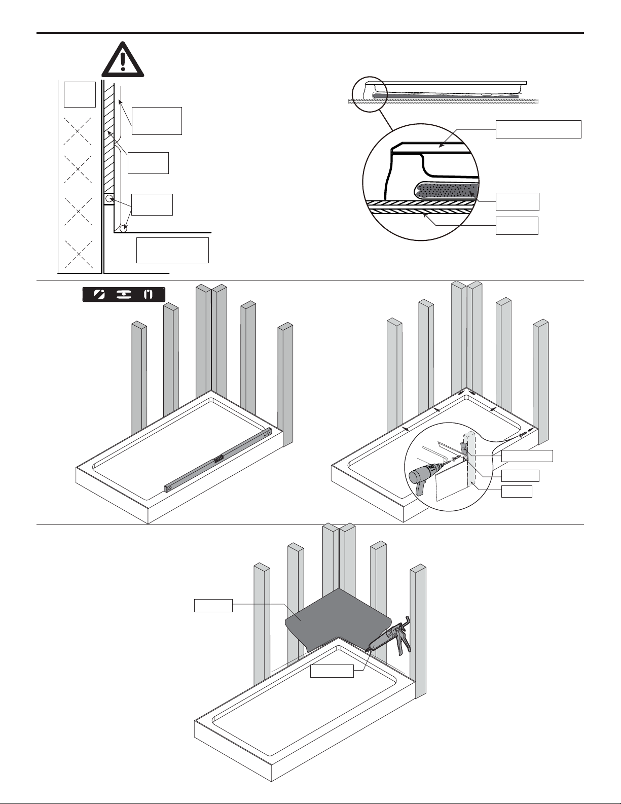
• Installtheshoweronaoorthatislevelandabletoaccommodatetheweightoftheunitandanoccupant.
• Consult local building codes and compliance standards prior to installation and ensure conformity.
• Afterinstallation,andfromtimetotime,checktheglassfortandnishtoensurethatnothinghascome
loose since installation.
• Keep this installation manual for future reference.
NOTICE
• Anymodicationoralterationfromwhatisspeciedinthisinstructionmanualwillvoidanyandallwarranty
on this product.
• The distributor is not responsible for any damage to the unit or personal property caused by improper
installation. If you disregard instructional warnings, you will void your warranty and possibly deal with water
damage.
• Consult www.ovedecors.com for any additional information or question on this product’s installation.
PREPARATION
You will need at least two people to install this unit properly.
Before beginning assembly of product, make sure all parts are present. Compare parts with package contents
list and hardware contents list. If any part is missing or damaged, do not attempt to assemble the product.
Estimated Assembly Time: Shower (120 min).
SAFETY INFORMATION

3
TABLE OF CONTENT
PACKAGE CONTENT.......................................................................................................................................... 5
HARDWARE CONTENT...................................................................................................................................... 6
TOOLS REQUIRED............................................................................................................................................. 6
SHOWER REVERSIBILITY.................................................................................................................................. 7
WALL TO WALL MEASURES............................................................................................................................. 7
BASE INSTALLATION GUIDELINES (OPTIONAL)............................................................................................ 8
FIXED PANEL INSTALLATION............................................................................................................................ 9
TOP TRACK INSTALLATION............................................................................................................................ 11
FRAME TRACK INSTALLATION..................................................................................................................... 12
WALL TRACK INSTALLATION......................................................................................................................... 13
DOOR INSTALLATION...................................................................................................................................... 15
STOPPER AND STRIPS INSTALLATION......................................................................................................... 18
HANDLE INSTALLATION & SEALING.............................................................................................................. 21
LIMITED PRODUCT WARRANTY......................................................................................................................22
CARE AND MAINTENANCE..............................................................................................................................22

4
PACKAGE CONTENT
H
I
M
U
O
T
MQ
U
EF
Q
R
G
S
J
D
CB
P
K
N
L
S
E
F
V

5
PACKAGE CONTENT
PART# DESCRIPTION QTY CODE
BDoor panel 199SGD3111-WM
CCenter panel 199SG31010-WM
DFixed panel 199SG31009-WM
EWall track 299STR3114-WM
FFrame track 299STR3123-WM
GTop track 199SGS0039-WM
HDoor handle 199SHA3108-WM
IDoor rolling track 199SWE0037-WM
JCener panel rolling track 199SWE0038-WM
KDoor bottom rolling track 199SWE3119-WM
LCenter panel bottom rolling track 199SWE3120-WM
MHorizontal rubber strips 299SRU0076
NBottom track 199STR3116-WM
OVertical rubber strip 199SRU0075
PMagnetic strip 199SRU0070
QAluminum covers 299STR3117-WM
RDoor magnetic track 199SRU0071
SVertical rubber strips (Long) 299SRU0072
TGasket 199SRU0073
UVertical rubber strips (Short) 299SRU0074
VTop track cover 199STR3124-WM
WHardware content 199SHW0126-WM

6
HARDWARE CONTENT
TOOLS REQUIRED
Pencil Screwdriver Level
Measuring Tape Silicone Rubber mallet Cutter
Safety glasses
Allen key
2mm & 2.5mm & 3mm Ratchet
Drill with ceramic tile bit
ø1/8”(3mm) & ø1/4”(6mm)
FFEEDDCCBBAA
Bottom bracket cap
4x
Wheels with thread
2 extra
GG
Screw
ST4x35mm
8+2
Wall Anchor
ø6x30mm
8+2
Fixed Panel support
1+1
HH
II
Screw
ST4x20mm
8+2
Screw
ST4x12mm
3+1
Top glass bracket
4x
Bottom glass bracket
4x
Plug
1x
Stopper
1x
Cap
2x
Support cap
2x
Top bracket cap
4x
KK LL MM NN OO
Ladder Wood stick
Screw
ST4x10mm
6+2
Screw
ST4x30mm
2+1
PP QQ

7
• This instruction is drawn up for an opening from right to left (see illustration B).
• For an installation from left to right (see illustration A), use the same instructions, but switch around the
panels: mirror effect.
SHOWER REVERSIBILITY
A B
WALL TO WALL MEASURES
Install the shower head on the door’s side! This will reduce the risk of leaking.
• Measure the thickness of your tiles on either side before installing the metal tracks. A thicker tile will limit
your space to install the shower panels.
• Make sure to have a tile to tile distance (D) between 1479mm (58 1/4 in) min. and 1498mm (59 in) max.
(see image).
Make sure to have a distance (D) from the left side tile
to the right side tile:
D Min: 1479mm (58 1/4 in)
D Max: 1498mm (59 in)

8
BASE INSTALLATION GUIDELINES (OPTIONAL)
1 2
4
Tile wall
Studs
Drywall
Silicone
5
Shower Base
3
Shower Base
Cement
Floor
Wood shim
Flange
Stud
Flange
Drywall
Silicone

9
1. Install the clamp (MM) on the track (N) using screw (DD), and then insert the cap (NN).
2-3. Placethehorizontalrubberstrip(M)onthetopofthexedpanel(D).
4-5. Placethehorizontalrubberstrip(M)onthebottomofthexedpanel(D).
FIXED PANEL INSTALLATION
M
D
D
M
M
D
D
M
N
NNN
DD
MM
5/8”
16mm
2
4
D
3
5
1
5/8”
16mm

10
1-2. Placethexedpanel(D)onthebottomtrack(N).
3. Placethetrack(F)onthexedpanel(D).
4. Secure the track (F) using screws (CC).
FIXED PANEL INSTALLATION
D
F
D
D
N
N
CC
D
F
D
N
1
2
3
4
N
3 holes side UP
2 holes side
DOWN
DF

11
1-2. Install the clamp (MM) on the top track (G) using screw (DD), and then insert the cap (NN).
3-4. Put the cap (HH) on the top track (G).
5-7.Placethetoptrack(G)onthexedpanel(D)andsecurethetrack(F)usingthescrews(CC&QQ).
TOP TRACK INSTALLATION
D
G
NN
DD
MM
G
G
G
F
CC
1
2
5
Helpful Hint
Use a ladder
to facilitate the
installation.
3
4
G
HH
G
6
G
MM
D D
G
MM
7
QQ

12
1. Slide the center panel rolling track (J) into the top track (G).
2-3. Install the track (F) on the top track (G) and the bottom track (N) using the screws (CC & QQ).
FRAME TRACK INSTALLATION
G
J
3 holes side UP
2 holes
side DOWN
Helpful Hint
Use a ladder
to facilitate the
installation.
1
2
3
CC G
CC N
F
F
QQ

13
1. Removetheprotectivelmfromthewalltracks(E),loosetheplasticscrewsandputthematthebottomof
their slot.
2-3. Place the wall tracks (E) on the tracks (F) by adjusting the position of the plastic screws.
4. Lock both tracks together by pushing the plastic screw downwards in the slots of the track (F).
5. Place the whole shower frame onto the base.
WALL TRACK INSTALLATION
FE
E
12
34
5

14
1-2.Usingtheplasticscrewsonthewalltrack(E),adjusttheleveloftheshowerframe.Also,makesureitts
snuggly between the 2 walls.
Note: A total of 8 plastic screws on the wall track (E) will help you adjust the level of the shower frame
and make it snuggly t between the 2 walls.
3. Mark the position of the holes of the wall tracks (E) on the wall.
4-5. Remove the shower frame and drill guide holes with a 1/4”(6mm) drill bit.
6-7. Insert the wall anchors (AA) into the wall and put back the shower frame in place.
8. Replacetheshowerframebackonthebase,andxtheshowerframeontothewallusingscrews(BB).
WALL TRACK INSTALLATION
ø1/4”
6mm
BB
AA
6 85
1 2
3 4
7

15
Note: 2 people are required for the following installation steps!
1-2. Install the center panel (C) on the rolling track (J) using glass brackets (EE) and caps (OO). Adjust the
level of the glass panel using the eccentric mechanism of the brackets.
3. Place the bottom rolling track (L) on the bottom track (N).
4-5. Fix the bottom rolling track (L) on the bottom track (N) using bracket (FF) and cap (GG). Make sure the
rollers of track (L) are in the passage of the bottom track (N).
6. Insert the vertical rubber strip (O) to the track (F).
DOOR INSTALLATION
C
J
EE
1 2
3
5 6
N
L
GG
FF
O
F
view from inside
view from inside
view from inside
view from inside
Eccentric
Helpful Hint
The center panel has an
up & down direction: make
sure the side with OVAL
holes is UP!
OO
4
L
N

16
1-2. Install the door (B) on the door rolling track (I) using bracket (EE) and cap (OO). Adjust the level of the
glass panel using the eccentric mechanism of the brackets.
3. Place the door magnetic track (R) on the door panel (B).
4. Find out which side of the magnetic strip (P) attracts the door’s magnet (R).
5. Insert the magnetic strip (P) into the track (F). Make sure to insert it with the attracting side facing the door’s
magnet.
DOOR INSTALLATION
B
I
EE
OO
view from inside view from inside
Eccentric
Helpful Hint
The door panel has an up
& down direction: make
sure the side with OVAL
holes is UP!
1
3
I
2
R
B
5
RP
P
F
4

17
1-2. Place the door (B) onto the top track (G), make sure the door can be closed well and the distances
between the panels (B & C & D) is approximately to 9/16”(14mm).
3-5. Install the door bottom rolling track (K) on the bottom track (N) using bracket (FF) and cap (GG). Make
sure the rollers of track (K) are in the passage of the bottom track (N).
DOOR INSTALLATION
34
K
N
B
GG
FF
view from inside
view from inside
9/16”
14mm
9/16”
14mm
BC
D
2
1
B
F
G
0”
0mm
5
K
N

18
1. Placethestopper(LL)onthetrack(F)onthexedpanelside.Findthecorrectpositionbyclosingthedoor
on the stopper. It should prevent the door from hitting the track, but should not hinder the opening and closing
motion of the door.
2-3. Mark the position of the stopper (LL) and drill a guide holes with ø1/8” (3mm) drill bit.
4. Install the stopper (LL) on the track (F) using screws (DD) and insert the block (KK).
STOPPER AND STRIPS INSTALLATION
B
LL
KK
1
34
DD
ø1/8”
3mm
F
view from inside
2
LL

19
1. Place the covers (Q) on the tracks (F). Use a rubber mallet to make it easier.
2. Put the cap (HH) on the bottom track (N).
3. Placethegasket(T)betweenthexedpanel(D)andthetrack(F).Useawoodstickforhelpasitwillt
tightly.
4. Install the top track cover (V) to the top track (G) using screws (PP).
STOPPER AND STRIPS INSTALLATION
T
Q
1
3
view from insideview from inside
HH
N
2
Helpful Hint
Use rubber mallet to push
the covers from top to
bottom.
Helpful Hint
Use the corner of a wood stick
to push the gasket inside, as the
opening is tight.
4
PP
V
G

20
1. Cut the surplus part of the vertical rubber strip (U).
2-3. Cut the surplus part of the vertical rubber strip (S).
4. Place the vertical rubber strips (S & U) on the panels (B & C).
5-6. Cut the surplus part of the other vertical rubber strip (S).
7. Place the vertical rubber strips (S & U) on the panels (C & D).
STOPPER AND STRIPS INSTALLATION
S
B
C
U
4
view from outside
1/16”
1.5mm
U
view from outside
1
3
2
1 3/8”
35mm
3/16”
4mm
1 3/8”
35mm
S
S
S
C
D
U
7
3/16”
4mm
5
1”
25mm
3/16”
4mm
S
6
1”
25mm
S
3/16”
4mm
This manual suits for next models
1
Table of contents
Languages:
Other OVE Indoor Furnishing manuals
Popular Indoor Furnishing manuals by other brands

BLACK RED WHITE
BLACK RED WHITE ONTARIO KOM/1SO Assembly manual

Blanco
Blanco BLANCOPRECIS 513-430 Specifications

Sunset Trading
Sunset Trading DLU-TLB-3660 Assembly instruction

Triarch
Triarch Indoor Lighting 31060-2 Assembly instructions

HJH office
HJH office WORKSPACE H III manual

Coaster
Coaster 460071 Assembly instructions