Owasys Owa4X User manual

Owa4X Platform
Integrator's Manual

The products described in this manual will conform to the essential Requirements in Radio
Equipment Directive (RED) 2014 53 EU, covering requirements included in EMC directive
2014 30 EU Low Voltage Directive 2014 35 EU as well as any other applicable requirements as
those from RoHS Directive 2011 65 EU.
The information contained in this document is the proprietary information of Owasys The
contents are confidential and any disclosure to persons other than the officers, employees,
agents or subcontractors of the owner or licensee of this document, without the prior written
consent of Owasys, is strictly prohibited.
Furthermore, no portion of this publication may be reproduced, stored in a retrieval system, or
transmitted in any form or by any means, electronic or mechanical, including photocopying and
recording, without the prior written consent of Owasys, the copyright holder.
Declaration of conformity can be found at www.owasys.com
Edition
Owasys publishes this manual without making any warranty as to the content contained
herein. Further Owasys reserves the right to make modifications to this manual due to
typographical errors, inaccurate information, or improvements to programs and or equipment at
any time and without notice. Such changes will, nevertheless be incorporated into new editions
of this manual.
All rights reserved.
© Owasys, 2020
Document number: BOK-100 9002
Trademarks
DISPOSAL OF OLD ELECTRICAL & ELECTRONIC EQUIPMENT APPLICABLE IN THE
EUROPEAN UNION AND OTHER EUROPEAN COUNTRIES WITH SEPARATE COLLECTION
SYSTEMS).
!" #
!
#
$
#
#

1 Safety and other precautions..........................................................................................5
1.1 General.....................................................................................................................5
1.2 Owa4X connections.................................................................................................5
1.3 Owa4X protections..................................................................................................5
1.4 EMC nstructions.....................................................................................................5
1.5 Exposure to RF Energy............................................................................................5
1.6 Antenna care and replacement.................................................................................6
1.7 Electronic devices....................................................................................................6
1.8 Blasting areas...........................................................................................................6
1.9 Children...................................................................................................................6
1.10 Explosive atmospheres..........................................................................................6
1.11 Handling the device...............................................................................................6
1.12 For owa4X/b..........................................................................................................7
2 ntroduction...................................................................................................................8
2.1 Overview.................................................................................................................8
2.2 What is the owa4X Platform...................................................................................8
2.3 Abbreviations...........................................................................................................8
2.4 Notes and Warnings.................................................................................................9
3 Getting started with the DK.........................................................................................10
3.1 ntroduction...........................................................................................................10
3.2 Development Kit Contents....................................................................................10
3.3 Physical Description..............................................................................................10
3.3.1 owa4X Physical Description...........................................................................10
3.3.2 Rear back cover options...................................................................................11
3.3.3 Developer’s Board Physical Description.........................................................15
3.3.4 Schematic of Developer’s Board....................................................................16
3.4 Connecting the owa4X Development Kit..............................................................19
3.4.1 Connecting owa4x to a PC..............................................................................20
3.4.2 Windows Hyperterminal..................................................................................20
3.4.3 Linux Minicom................................................................................................20
4 Owa4X Main Features.................................................................................................22
4.1 Hardware Features.................................................................................................22
4.1.1 Microprocessor and memory...........................................................................22
4.1.2 GSM/GPRS System.........................................................................................22
4.1.3 GNSS...............................................................................................................22
4.1.4 Hardware nterfaces.........................................................................................22
4.1.5 nternal Temperature........................................................................................33
4.1.6 System Time and HW time..............................................................................34
4.1.7 Accelerometer..................................................................................................34
4.1.8 Watchdog.........................................................................................................34
4.1.9 Optional Features.............................................................................................35
5 Power management......................................................................................................37
5.1 Functional states....................................................................................................37
5.2 System halt............................................................................................................37
6 Firmware Specifications..............................................................................................39
6.1 General Description of Firmware..........................................................................39
6.2 Boot Loader...........................................................................................................39
6.3 Linux Kernel..........................................................................................................39
6.4 File System............................................................................................................39
6.5 Recovery File System............................................................................................39

6.6 Starting to develop the customer application........................................................40
6.6.1 Available AP s.................................................................................................40
6.6.2 CAN Bus FMS AP .........................................................................................41
6.6.3 RS232 Driver...................................................................................................41
6.6.4 Software Application Notes.............................................................................41
7 Updating owa4x FW....................................................................................................42
7.1 uSD........................................................................................................................42
7.2 TFTP server...........................................................................................................43
7.3 Creating a customized UB FS image from owa4x FS tree...................................44
7.4 Creating a customized UB FS image from current FS running in owa4x.............46
7.5 Starting the recovery image...................................................................................46
7.5.1 FW < 1.1.x.......................................................................................................46
7.5.2 FW >= 1.1.x.....................................................................................................47
8 U-boot environment.....................................................................................................49
8.1 System boot protection..........................................................................................49
9 systemd - system and service manager........................................................................50
9.1 ntroduction...........................................................................................................50
9.2 Boot process..........................................................................................................50
9.3 Unit files................................................................................................................50
9.3.1 Enabling and disabling services......................................................................51
9.3.2 Grouping services............................................................................................51
9.4 System logging......................................................................................................51
10 Backup FS..................................................................................................................52
11 nstallation.................................................................................................................52
11.1 owa4x dimensions................................................................................................52
11.2 Mounting the unit.................................................................................................52
11.2.1 Antenna Location and installation.................................................................52
11.2.2 Antenna Tuning.............................................................................................53
11.2.3 Antenna Cable Routing..................................................................................53
11.3 Power connection.................................................................................................53
11.4 Choosing a location.............................................................................................53
11.5 Opening the unit...................................................................................................54
11.6 Mounting and fixing the unit...............................................................................54
12 Technical data summary............................................................................................56
12.1 General Specification..........................................................................................56
12.2 Mechanical Description.......................................................................................56
12.3 Power nterface....................................................................................................56
12.4 GSM/GPRS Specifications..................................................................................56
12.4.1 Owa4x with HW < R4...................................................................................56
12.4.2 Owa4x with HW = R4...................................................................................57
12.5 GNSS Specifications...........................................................................................57
12.6 Environmental Specifications..............................................................................58
12.7 Battery Backup....................................................................................................58
13 References.................................................................................................................59
14 History.......................................................................................................................60
Illustration 1: owa4x frontal view.................................................................................10
Illustration 2: WiFi-BT antenna placement...................................................................11
Illustration 3: owa4x rear view.....................................................................................11
Illustration 4: No IP67 rear back cover........................................................................12
Illustration 5: IP67 rear back cover..............................................................................12
Illustration 6: IP67 rear back cover with cable gland...................................................13

Illustration 7: IP67 rear back with cable gland and M12..............................................13
Illustration 8: M12 connector pin-out...........................................................................13
Illustration 9: M12 and cable gland..............................................................................14
Illustration 10: Developers board physical description.................................................15
Illustration 11: Developers board schematic................................................................16
Illustration 12: Insertion of BAT118 6500.....................................................................23
Illustration 13: Insertion of BAT 418 6500....................................................................24
Illustration 14: USB pinout...........................................................................................24
Illustration 15: Main connector....................................................................................25
Illustration 16: Digital output typical loads...................................................................28
Illustration 17: owa4x RS485 bus................................................................................29
Illustration 18: RJ45 connector....................................................................................32
Illustration 19: Accelerometer axis...............................................................................34
Illustration 20: IP67 cover with Ethernet option...........................................................35
Illustration 21: Accelerometer Gyroscope axis...........................................................35
Illustration 22: owa4x dimensions...............................................................................52
Illustration 23: Opening process..................................................................................54
Illustration 24: Installation brackets measurements.....................................................55

IMPORTANT: FOR THE EFFICIENT AND SAFE OPERATION OF YOUR owa4x MODULE,
READ THIS INFORMATION BEFORE USE!
Care must be taken when handling the unit. It must not be dropped or exposed to excessive
heat.
Only authorized staff can disassemble the product. In case the product was disassembled by
non-authorized people, the warranty is no longer valid.
Do not push objects into openings of your device. Doing so can cause fire or electric shock
by shorting out interior components.
The owa4x product has not been designed for outdoor conditions. If the product is exposed
to severe conditions beyond the limits specified in Environmental Specifications, the product
could be damaged.
Keep the device away from radiators and heat sources. Do not use the owa4X in wet or
humid environments, for example, near the bath tub, sink, or swimming pool or in a damp
basement.
The device may become hot during normal operation, so switch it off and wait for a while
before handling it.
Do not clean the device when powered. Clean it with a soft cloth. Do not use liquid or
aerosol cleaners, which may contain flammable substances.
The highest internal voltage applied to the owa4x unit can be 48Vdc (36Vdc for owa4x R4)
and complies with low voltage European directive.
The power supply can be made with a battery or continuous voltage supply with reinforced
isolation, and limited in power to a maximum of 8A and 100VA.
Before you connect the device to a power supply, check the voltage and current rating to
ensure that the required ones match the available power source. Exceeding the specified
input range may cause unexpected operation and or irreversible damage to owa4X.
To remove the device from all power sources turn the device off and disconnect it from the
power supply.
Be sure that nothing rests on the connected cables and that the cables are not located
where they can be tripped over or stepped on.
Applying loads outside of the range specified may result in unintended operation and or
possible permanent damage to owa4x. If there is any uncertainty, please contact owasys
Customer Support at [email protected].
The owa4x inputs have some protections to avoid damages when erroneously connecting to
a power supply for example or due to voltage peaks:
•Power supply input (V_IN) reverse voltage protection and overvoltage protection
zener diode. External fuse of 2 A should be added.
•Power output (V_OUT) overcurrent protection.
•DIOs overcurrent protection.
Use shielded signal cables to ensure that you maintain the appropriate EMC classification
for the intended environment.
Keep cables as short as possible, not longer than 3 meters.
! "#$
Minimize RF energy exposure by limiting the duration of GSM calls and operating the unit
efficiently.

The antenna must be mounted in such a position that no part of the human body rests close
to any part of the antenna. The product is intended to be used with an external GSM
antenna, located at least at 20 cm. away from any part of the human body. Those
installations not complying with this statement are responsible for providing SAR
measurement reports and corresponding declaration.
Do not hold the antenna during a call since it affects call quality and can cause the module to
operate at a higher power level than needed.
% &'
Do not use the product with a damaged antenna because when the antenna comes into
contact with the skin, a minor burn may result. Replace the antenna immediately.
Use only antennas that are according to the technical specifications. Antennas that do not
fulfil the specifications could damage the product and may contravene local RF emissions
regulations or invalidate type approval.
( )
Most electronic devices are shielded from RF energy. However RF energy may cause some
malfunctioning of improperly shielded electronic devices.
When the product is mounted in a vehicle, check your vehicle to determine that all on board
electronic equipment is adequately shielded from RF energy.
In the same way, when the product is in the proximity of medical devices (hospitals, etc.)
check with the manufacturer of medical equipment to determine if they are properly shielded.
This equipment should never be operated on an aircraft.
* +$
To avoid interfering with blasting operations, turn the unit OFF in these kind of areas or in
areas ported “turn off your two way radio”.
Construction crew often uses remote control RF devices to set off explosives.
,
Do not allow children to play with owa4X. It is not a toy and they could hurt themselves or
others. Children could also damage the unit.
- )'
Do not operate this product in environments containing explosive materials or vapour. This
includes petrol service stations.
The unit accessories could generate sparks that can cause an explosion or fire resulting in
bodily injury or even death.
To avoid interfering with blasting operations, turn the unit off in areas posted “blasting area”.
Do not transport or store flammable gas, liquid or explosives, in the compartment of your
vehicle which contains owa4X or its accessories.
.$)
Observe the following safe-handling guidelines to prevent damage to owa4X:
When setting up the device for work, place it on a flat level surface.
Protect the device from environmental hazards such as dirt, dust, food, liquids,
temperature extremes, and overexposure to sunlight.
When you move your device between environments with very different
temperature and or humidity ranges, condensation may form on or within the
device. To avoid damaging it, allow sufficient time for the moisture to evaporate
before using the device.

When taking the device from low-temperature conditions into a warmer
environment or from high-temperature conditions into a cooler environment, allow
the device to acclimate to room temperature before turning on power.
When disconnecting a cable, pull on its connector or on its strain-relief loop, not
on the cable itself. As you pull out the connector, keep it evenly aligned to avoid
bending any connector pins. Also, before you connect a cable make sure both
connectors are correctly oriented and aligned.
#/0
These models include the optional lithium-ion battery backup. Do not dispose off the battery
along with household waste. Contact your local waste disposal agency for the address of the
nearest battery disposal site.
The battery poses a burn hazard if you handle it improperly. So do not disassemble or
handle it. If the battery is damaged, electrolyte may leak from the cells and may cause
personal injury.
Keep the battery away form children.
When the battery is heated to excessive temperatures, its cells could explode or vent,
posing a risk of fire.

))
The owa4X Integrators Manual describes how to install, set up, and configure owa4X
Platform product.
The owa4X device can be provided with battery backup as an option. In this case, the
product is labelled with a “ b” at the end, e. g.: owa4X b.
This first section provides a brief overview of the product followed by a “Getting Started”
chapter. Further sections go into more detail on the hardware specifications and various
firmware functions available to the development of the user application. Application notes,
technical specifications, troubleshooting, and a peripheral devices reference, complete this
manual.
12'
The owa4X product provides a powerful platform for management of geographically
distributed equipment. The owa4X unit integrates a GSM GPRS communication system
with embedded IP functionality, allowing an efficient and bi-directional transmission of
information across the cellular wireless network. Additionally, the owa4X unit includes a
GNSS receiver for reception of positioning information.
The basic features of this product are:
Cortex A8 with 512MB DDR3 and 1GB NAND Flash
Linux Kernel 4.4.19 or 4.14.67
Debian Filesystem
User-friendly programming environment with a complete set of APIs.
UMTS HSPA+: Five Band 800 850 900 1900 2100MHz
GSM GPRS EDGE: Quad Band GSM 850 EGSM900 GSM1800 GSM1900.
GNSS Receiver 72-channel with -160dBm tracking and navigation sensitivity
Extensive range of external interfaces (RS-232, digital and analog I Os…).
CAN interface.
Programmable 3 axis accelerometer.
MicroSD card holder.
Optional feature are:
Audio CODEC
Ethernet 10 100
Dead reckoning
Programmable 9 axis sensor, (accelerometer, gyroscope, magnetometer)
Kline
IP67 enclosure
Internal antennas
WiFi + BT module
Up to 4 CAN bus interfaces.
USB
Check data sheet and product variants for the exact features available in your device.
&00)

API Application Programming Interface
CAN Controller Area Network
CEP Circular Error Probability
CPU Central Processing Unit
DTE Data Terminal Equipment
EDGE Enhanced Data GSM Environment
GPRS General Packet Radio Service
GNSS Global Navigation Satellite System
GSM Global System Mobile
HSDPA High-Speed Downlink Packet Access
HW Hardware
MIPS Millions of Instructions Per Second
MMU Memory Management Unit
NC Not Connected
O&M Operation and Maintenance
OS Operating system
PWM Pulse Width Modulation
RTC Real Time Clock
SAR Specific Absorption Rate
SIM Subscriber Identity Module
SMS Short Message System
SW Software
TTY TeleType Writer
UMTS Universal Mobile Telecommunications System
USB Universal Serial Bus
VSWR Voltage Standing Wave Ratio
2.1 Abbreviations list
31$
Note – Notes provide additional information about the products.
Cautions – Cautions alert you to situations that could cause hardware damage or software
error.

%&'"()*+,,-,,.".
$45
This section explains the steps to install and configure the owa4X UDK
development kit to begin with the set-up of the customer application.
Starting with the list of components the development kit includes, the document
follows with a physical description of the unit, the steps for mounting and
connecting the components and then, the software set up procedure.
Finally, there is a description of the operating modes and the indicator lights of
the unit.
4)'5
Refer to the documentation included with your Development Kit to know which
are the items actually included in the package.
24
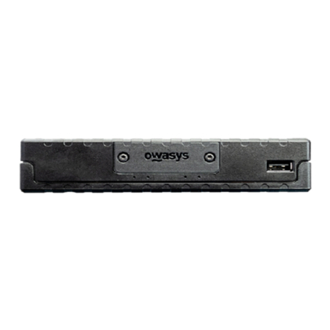
3.3.1 owa4X Physical Description
The standard unit has GSM and GNSS external antenna connectors, while
Bluetooth and WiFi antennas are internal, as shown in the following image.
The AUX LTE antenna will only be available in owa4x with HW R4, which
mounts a LTE module.
+,
Illustration 1: owa4x frontal view

%&'"()*+,,-,,.".
When using either WiFi or Bluetooth functionality, try to make sure that the
installation lets a free view of this side of the unit. The “UP” mark shows the
side that must be upwards, and the front should also not be in contact or very
close of metallic surfaces.
Illustration 3: owa4x rear view
3.3.2 Rear back cover options
There are 3 possible options for the rear back cover, depending on the IP
requirements.
++
Illustration 2: WiFi-BT antenna place ent

%&'"()*+,,-,,.".
3.3.2.1 No IP67 rear back cover
This back cover is open and does not support the IP67 requirements.
3.3.2.2 IP67 rear back cover
This back cover supports IP67 requirements, and has no opening at all.
3.3.2.3 IP67 rear back cover with cable gland
This back cover supports IP67 requirements, and has a cable gland to connect
to the Ethernet interface in the back side of the unit.
+.
Illustration 4: No IP67 rear back cover
Illustration 5: IP67 rear back cover

%&'"()*+,,-,,.".
3.3.2.4 IP67 rear back with cable gland and M12 cable
This back cover supports IP67 requirements, has a cable gland and also a
cable with a M12 connector, that gets out the Ethernet connection signals.
This is the pin-out of the M12 connector:
+/
Illustration 8:
M12 connector
pin-out
Illustration 6: IP67 rear back cover with cable
gland
Illustration 7: IP67 rear back with cable gland and
M12

%&'"()*+,,-,,.".
M12 RJ45 Eth)
1 TD+ 1 TX+
2 RD+ 3 RX+
3 TD- 2 TX-
4 RD- 6 RX-
The M12 connector is connected to the cable gland.
+&
Illustration 9: M12 and cable gland

%&'"()*+,,-,,.".
3.3.3 Developer’s Board Physical Description
Following figure shows the layout of the Development Board connectors:
+0
Illustration 10: Developers board physical description

%&'"()*+,,-,,.".
3.3.4 Schematic of Developer’s Board
+1
Illustration 11: Developers board sche atic

%&'"()*+,,-,,.".
Number Connector
J1 Connector for audio and analog inputs from owa4x
J2 Connector for digital inputs from owa4x
J3 Connector for digital outputs from owa4x
J4 Connector for CAN KLINE and RS485 from owa4x
J5 Connector for power, and RS232 interfaces from owa4x
X3 Jack for DC power supply, 12V or 24V.
J6 DB9 for main uart, UART4
J7 Connector for external devices
J8 Connector for external devices
J9 Connector for external devices
J10 Connector for external devices
J11 Connector for external devices
J12 Jack speaker
J13 Jack microphone
3.1 Connectors of developer kit
In the developers zone of www.owasys.com there is available to download the
schematics of the DK board in pdf format, which has better quality than the
image on this document.
Power may be connected to either X3 or J7. The power input range is 9V – 48V
or 9V – 36V for HW R4 or newer, and a fuse F1 is mounted in the DK board to
prevent damages to other components in case of over-voltage.
Connectors J1 to J5 are used to connect the necessary signals to the owa4X.
All the signals are available in the connectors mounted in the front in case they
have to be connected to external devices.
In order to test the analog inputs, potentiometers are provided. The switch may
select the potentiometer or leave the signal open for an external signal source
to be connected.
Digital inputs have switches to change the default status, in order to test the
behaviour of all them.
Digital outputs have led indicators, to indicate when they have been activated.
Pin Signal
J1-1 MICN
J1-2 MICP
J1-3 GND
J1-4 SPKN
J1-5 SPKP
J1-6 GND
J1-7 AIN-3
J1-8 AIN-2
J1-9 AIN-1
J1-10 AIN-0
+2
Be careful when connecting the DIO cables to the DIN J2 connector. If
instead of using them as inputs, are activated the outputs that are
multiplexed on them, the unit may be damaged. Have special care with DIO8
and DIO9, activating their output while connected to the J2 connector and
closed switch, will damage the device.

%&'"()*+,,-,,.".
3.2 Connector J1 of DK
Microphone and speaker signals are connected to Jacks for the microphone
and speaker connection.
Analog inputs are connected to potentiometers through switches. The switches
should be in OFF position if external signal sources are to be applied.
Pin Signal
J2-1 DIN-9
J2-2 DIN-8
J2-3 DIN-7
J2-4 DIN-6
J2-5 DIN-5
J2-6 DIN-4
J2-7 DIN-3
J2-8 DIN-2
J2-9 DIN-1
J2-10 DIN-0
3.3 Connector J2 of DK
Digital inputs have pull downs in the Development kit and a switch to connect to
a high level for the input testing.
Digital input 6 is inverted, so it has a pull up by default, and the switch connects
the input to GND.
If external signal sources are to be connected the switches should be in OFF
state.
Pin Signal
J3-1 OUT-9(HS)
J3-2 OUT-8(HS)
J3-3 OUT-7
J3-4 OUT-6
J3-5 OUT-5
J3-6 OUT-4
J3-7 OUT-3
J3-8 OUT-2
J3-9 OUT-1
J3-10 OUT-0
3.4 Connector J3 of DK
Digital outputs 0 to 7 are open drain, so they give a low value when active.
Digital outputs 8 and 9 are High side so they provide a high value (V_IN) when
active. All the signals have LEDs to provide a visual indication of the status of
the output. The LED will be on when the output is activated.
Pin Signal
J4-1 RS485B
J4-2 RS485A
J4-3 GND
J4-4 KLINE_2
J4-5 KLINE_1
J4-6 CANL2
+3

%&'"()*+,,-,,.".
J4-7 CANH2
J4-8 GND
J4-9 CANL1
J4-10 CANH1
3.5 Connector J4 of DK
Note that to use RS485 or CAN, a 120Ω termination resistor must be placed at
each end of the network. In the development kit there is a termination resistor of
120 ohms soldered for each of the buses.
:
Pin Signal Function
J5-1 TXD-4 TX UART4 (Main uart)
J5-2 RXD-4 RX UART4 (Main uart)
J5-3 TXD-5 RTS-4 TX UART 5
J5-4
RXD-5 CTS-4
RX UART 5
J5-5 TXD-1 TX UART1
J5-6 RXD-1 RX UART1
J5-7 V_OUT +5V voltage output 500mA MAX
J5-8 ON OFF Connect to ground to power down
J5-9 V_IN Power input
J5-10 GND Ground
3.6 Connector J2 of UDK
RS232 interface signals of the UART4 go to J6 DB9 connector too.
J7, J8, J9, J10, J11 connectors are directly connected to signals coming from
the owa4x connectors in order to connect external devices or signal sources.
$4)'5
This section describes the owa4X development kit components connections.
The steps for mounting the components in owa4X are the following:
Antennas: Connect the antennas used for the application, 3G, GNSS etc.
DB9 RS-232 Serial connector: Connect a RS232 connector, or USB to RS232
connetor to the PC to debug the unit.
Owa4x Signals: Connect the signals needed to the development kit in the
connectors J1 to J5. The development kit has specific use for each of the signal
in each of the connections. DIOs should be connected to the DIN or DOUT
depending on which feature is to be tested. RJ11 cable:
microSIM card: The microSIM card should be introduced in the SIM card
compartment. The SIM card contacts shall be faced upwards. Push the SIM
card until hearing a click and then lock it with the flap.
AC/DC Power supply: Provided AC DC power supply adaptor can be
connected to developers board, connector X3, and to a suitable AC main outlet.
Alternatively a laboratory power supply can be connected to V_IN and GND at
J7 connector.
+-
Table of contents
Other Owasys Gateway manuals