Figure
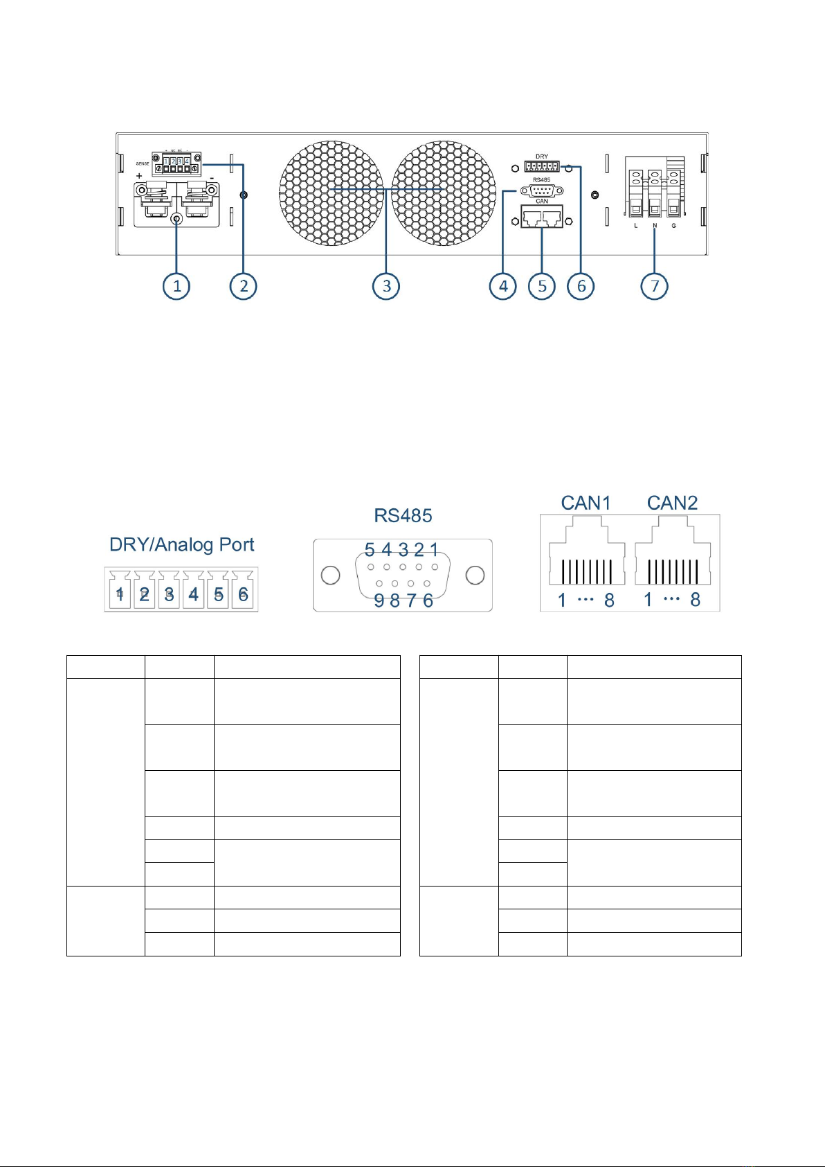
Figure 1: Back panel
......................................................................................................................................................
1
Figure 2: Interface
..........................................................................................................................................................
1
Figure 3: Schematic diagram of voltage compensation wiring
................................................................................
2
Figure 4: Parallel schematic diagram
...........................................................................................................................
2
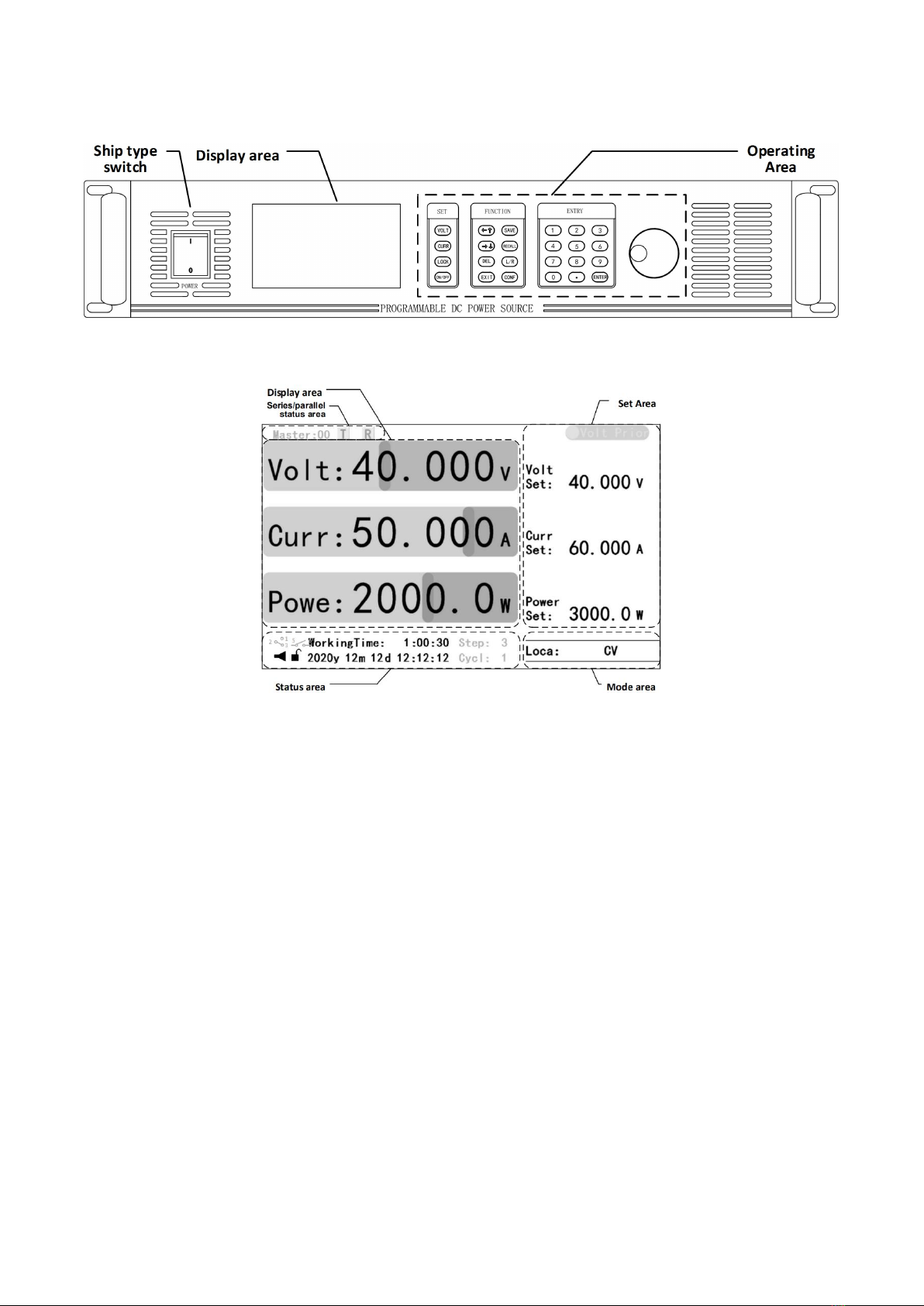
Figure 6: Front panel
.....................................................................................................................................................
3
Figure 5: Display area
....................................................................................................................................................
3
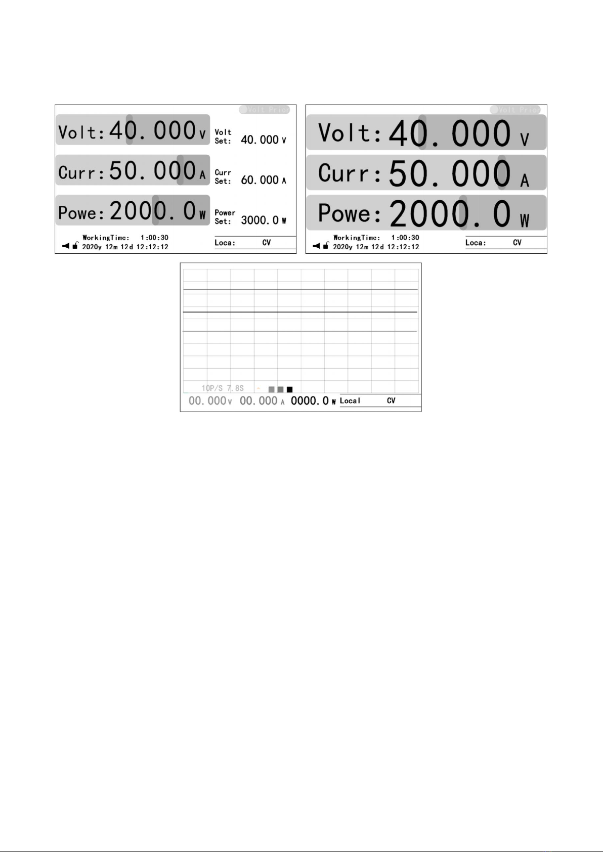
Figure 7: Homes
............................................................................................................................................................
4
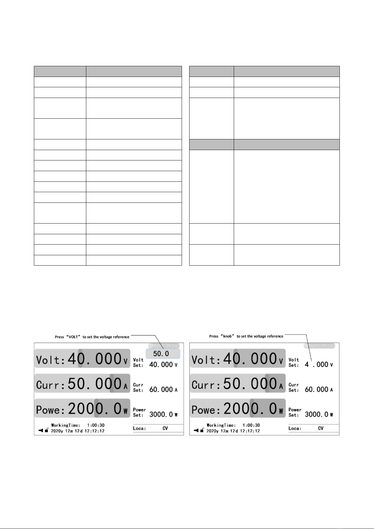
Figure 8: Reference setting
...........................................................................................................................................
5
Figure 9: Menu
...............................................................................................................................................................
7
Figure 10: Step Mode
....................................................................................................................................................
9
Table
Table 1: Defines of interface
.........................................................................................................................................
1
Table 2: Key description
................................................................................................................................................
5
Table 3: Application mode
...........................................................................................................................................
8
Table 4: Steps mode
.....................................................................................................................................................
8
Table 5: Charge Mode
..................................................................................................................................................
9
Table 6: Sine wave generator
.....................................................................................................................................
10
Table 7: Triangle wave generator
..............................................................................................................................
10
Table 8: Rectangular/pulse/trapezoidal wave generator
........................................................................................
11
Table 9: Line generator
...............................................................................................................................................
11
Table 10: Information
..................................................................................................................................................
12
Table 11: Error log
.......................................................................................................................................................
12
Table 12: Operating log
..............................................................................................................................................
12
Table 13: Event log
......................................................................................................................................................
12
Table 14: System setting
.............................................................................................................................................
13
Table 15: UI setting
.....................................................................................................................................................
13
Table 16: Communication setting
.............................................................................................................................
14
Table 17: Function setting
..........................................................................................................................................
14
Table 18: Output timing setting
................................................................................................................................
15
Table 19: Parallel connection
.....................................................................................................................................
16
Table 20: Interface Setting
..........................................................................................................................................
16
Table 21: Dry contact output
.....................................................................................................................................
16
Table 22: Dry contact input
........................................................................................................................................
16
Table 23: Analog interface setting
.............................................................................................................................
17
Table 24: Protect setting
.............................................................................................................................................
18
Table 25: Other protects
.............................................................................................................................................
18
Table 26: Under-voltage/under-current protection
...............................................................................................
18
Table 27: Short-circuit protect
...................................................................................................................................
19
Table 28: Switch of protects
.......................................................................................................................................
19
Table 29: Reset
............................................................................................................................................................
20