CARACTERISTICAS PRINCIPALES
DEL GENERADOR
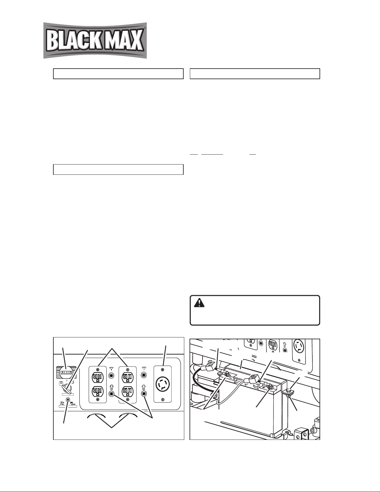
PANEL DE CONTROL
A. Receptáculo dúplex de 120 voltios, 20 amperes
20 amperes de la corriente se pueden dibujar de cada mitad del
receptáculo. Sin embargo, la potencia total extraída debe mantenerse
dentro de los valores nominales de la placa de identicación. Estos
receptáculos pueden usarse junto con el receptáculo de cierre giratorio
siempre y cuando el generador no esté sobrecargado.
B. Receptáculo de cierre giratorio de 120/240 voltios, 30 amperes
Puede extraerse un máximo de 30 amp desde el receptáculo de
120/240 voltios siempre y cuando sea el único receptáculo usado. Sin
embargo, la corriente debe limitarse al valor nominal de la placa de iden-
ticación. Si se utiliza un receptáculo de 120/240 voltios junto con los
receptáculos de 120 voltios, la carga total extraída no debe exceder los
valores nominales de la placa de identicación.
C. Interruptor
Los receptáculos se protegen mediante un cortacircuitos de CA.
Si se sobrecarga el generador u ocurre un cortocircuito externo, el cort-
acircuitos saltará. Si esto ocurre, desconecte todas las cargas eléctricas
y trate de determinar la causa del problema antes de usar el generador
nuevamente. Si la sobrecarga causa que salte el cortacircuitos, reduzca
la carga. NOTA: Si salta continuamente el cortacircuitos, se podría
dañar el generador o el equipo. El cortacircuitos puede restaurarse
pulsando el botón del cortacircuitos.
D. El motor On/Off (En/De) Interruptor
E. Retén para el cordón
El retén para el cordón es una característica exclusiva que se
utiliza para impedir que los tapones se salgan de los receptáculos de
120 voltios.
F. Horómetro analógico
G. Protección de apagado del circuito por baja cantidad de aceite
Motor Honda GX390
Arranque eléctrico
Manga de hierro fundido del cilindro
Sistema de alerta que se activa cuando el nivel de lubricante es
bajo
Receptáculos sobre el panel de control
Retén para el cordón
El regulador automático del voltaje
Tanque metal de combustible con capacidad de 30.3 litros
(8 galones)
Horómetro analógico
Juego de transporte
El modelo de este generador se proporciona con capacidades de
arranque tanto de impacto trasero como eléctrico. Evite el uso pro-
longado de arranque con manivela, pues esto puede dañar el motor.
La batería que se suministra es de plomo-ácido, de 12 voltios
nominales, sellada y recargable y se puede poner en funcionamiento
en cualquier posición sin que presente fugas. Cumple con las
regulaciones de baterías antiderrame. Su cómodo tamaño ofrece una
reducción del 30% sobre otras baterías convencionales.
Longitud = 7.14 pulg, Ancho = 3.03 pulg, Altura = 6.59 pulg
Altura = 12.56 lb
18AH nominal
Reconocida por UL
Lista de piezas del kit de batería
Artículo Descripción Cant.
A *Perno, M5 x M12................2
B. *Tuerca 5mm .......................2
C. *Arandela plana M5.............2
*Todas las partes son estándar y puede encontrarlas en su ferretería
local.
Nota: Los generadores nuevos de marca se envían con las
conexiones de la batería sin conectar. Las terminales positiva y
negativa deben conectarse con la batería antes de que se ponga
en marcha la función Arranque eléctrico.
Conexión inicial de la batería: Consulte las Instrucciones de instalación
que aparecen a continuación.
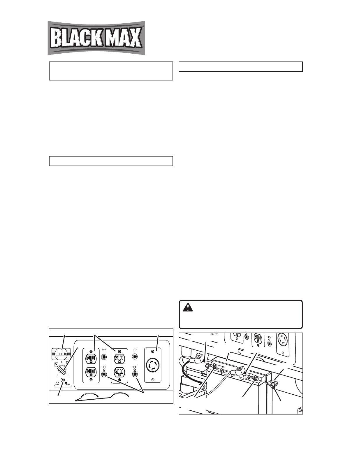
Instalación e Extracción de la batería:
Instalación: Acople la nueva batería, o vuelva a instalarla,
como se muestra a continuación: Retire las tuercas y los pernos del
soporte de la pila; retire el soporte y colóquelo a un lado. Por medio
del perno, tuerca, y la arandela suministrados, conecte el cable rojo
con la terminal positiva (+) y el cable negro con la terminal negativa
(-). Coloque la batería en la posición provista. Reemplace el soporte
de la pila. Coloque los pernos y las tuercas; apriete rmemente.
Asegúrese de que todas las conexiones estén rmes.
Extracción: Retire las tuercas y los pernos del soporte de la
pila; retire el soporte y colóquelo a un lado. Retire la tuerca y el
perno de la terminal negativa y la positiva, teniendo cuidado de no
causar cortocircuito en las terminales. (Un cortocircuito al juntar las
terminales puede causar chispas, daños a la batería o al generador y
hasta quemaduras o explosiones.) Siempre observe las advertencias
de seguridad que se suministran con la batería. Quite la batería y
deséchela según lo establecido por las reglamentaciones locales y
estatales.
ADVERTENCIA:
Para reducir el riesgo de electrocución o explosión, no cause
cortocircuito en las terminales de las baterías o realice la carga en un
recipiente sellado. Mantenga alejadas las chispas y las llamas.
ARRANQUE ELÉCTRICO
E