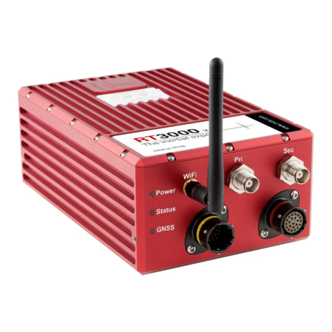
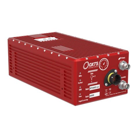
OXTS AV200 Use and care manual

AV200
Hardware
Integration Manual

Oxford Technical Solutions Ltd www.oxts.com Page 2 of 26
Legal notices
Information furnished is believed to be accurate and reliable. However, Oxford Technical Solutions
Limited assumes no responsibility for the consequences of use of such information nor for any
infringement of patents or other rights of third parties which may result from its use. No licence is granted
by implication or otherwise under any patent or patent rights of Oxford Technical Solutions Limited.
Specifications mentioned in this publication are subject to change without notice and do not represent
a commitment on the part of Oxford Technical Solutions Limited. This publication supersedes and
replaces all information previously supplied. Oxford Technical Solutions Limited products are not
authorised for use as critical components in life support devices or systems without express written
approval of Oxford Technical Solutions Limited.
All brand names are trademarks of their respective holders.
The software is provided by the contributors “as is” and any express or implied warranties, including,
but not limited to, the implied warranties of merchantability and fitness for a particular purpose are
disclaimed. In no event shall the contributors be liable for any direct, indirect, incidental, special,
exemplary, or consequential damages (including, but not limited to, procurement of substitute goods or
services; loss of use, data, or profits; or business interruption) however caused and on any theory of
liability, whether in contract, strict liability, or tort (including negligence or otherwise) arising in any way
out of the use of this software, even if advised of the possibility of such damage.
Copyright notice
© Copyright 2021, Oxford Technical Solutions.
Revision
Document Revision: 211025 (See Revision History for detailed information).
Contact details
Oxford Technical Solutions Limited
Park Farm Business Centre
Middleton Stoney
Oxfordshire
OX25 4AL
United Kingdom
Tel: +44 (0) 1869 814 253
Fax: +44 (0) 1869 251 764
Web: http://www.oxts.com
Email: support@oxts.com

Oxford Technical Solutions Ltd www.oxts.com Page 3 of 26
Warranty and liability
Oxford Technical Solutions Limited warrants its products to be free of defects in materials and
workmanship, subject to the conditions set forth below, for a period of one year from the Date of Sale.
“Date of Sale” shall mean the date of the Oxford Technical Solutions Limited invoice issued on delivery
of the product. The responsibility of Oxford Technical Solutions Limited in respect of this warranty is
limited solely to product replacement or product repair at an authorised location only. Determination of
replacement or repair will be made by Oxford Technical Solutions Limited personnel or by personnel
expressly authorised by Oxford Technical Solutions Limited for this purpose.
In no event will Oxford Technical Solutions Limited be liable for any indirect, incidental, special, or
consequential damages whether through tort, contract or otherwise. This warranty is expressly in lieu
of all other warranties, expressed or implied, including without limitation the implied warranties of
merchantability or fitness for a particular purpose. The foregoing states the entire liability of Oxford
Technical Solutions Limited with respect to the products herein.
Any use or misuse of the product in a manner not intended may impair the protection provided. Improper
installation or usage of the device can lead to malfunction, loss of data, equipment damage, and
physical injury. The user is responsible for conducting a proper risk assessment when integrating the
product. Please contact OxTS if you believe any service or repair is required on your product.
It is possible to connect the product to a vehicle CAN bus for gathering data, in which case there is
potential to influence the behaviour of electronic control units. Therefore, you must always ensure that
the product is used in a safe manner by trained personnel.

Oxford Technical Solutions Ltd www.oxts.com Page 4 of 26
Contents
Legal notices .......................................................................................................................................2
Copyright notice...................................................................................................................................2
Revision...............................................................................................................................................2
Contact details.....................................................................................................................................2
Warranty and liability ...........................................................................................................................3
Introduction..............................................................................................................................................6
Related documents..............................................................................................................................6
Scope of delivery.................................................................................................................................6
Conformance notices ..............................................................................................................................8
Regulator testing standards.................................................................................................................8
Hardware description ..............................................................................................................................9
Overview..............................................................................................................................................9
Dimensions........................................................................................................................................10
LED definitions ..................................................................................................................................11
Coordinate frame...............................................................................................................................12
Design-in...............................................................................................................................................14
Main connector..................................................................................................................................14
PPS................................................................................................................................................14
User cable..........................................................................................................................................15
Ethernet configuration .......................................................................................................................16
Mounting............................................................................................................................................17
Orientation and alignment..............................................................................................................17
Antennas............................................................................................................................................18
Antenna placement and orientation...............................................................................................18
Internal storage..................................................................................................................................19
Electrical specifications.........................................................................................................................20
Specifications........................................................................................................................................21
Notes on specifications......................................................................................................................22
Export control classification number..................................................................................................22
Appendix A –Drawings.........................................................................................................................23
Revision history.....................................................................................................................................25
List of figures
Figure 1: AV200 front view......................................................................................................................9
Figure 2: AV200 top view......................................................................................................................10
Figure 3: AV200 dimensions and measurement origin point (mm).......................................................11
Figure 4: AV200 coordinate frame axes ...............................................................................................13

Oxford Technical Solutions Ltd www.oxts.com Page 5 of 26
Figure 5: AV200 main connector pin layout..........................................................................................14
Figure 6: PPS waveform .......................................................................................................................15
Figure 7: AV200 user cable...................................................................................................................15
Figure 8: AV200 mounting points (mm) ................................................................................................17
Figure 9: Dual antenna orientation........................................................................................................18
List of tables
Table 1: Supplementary manuals ...........................................................................................................6
Table 2: AV200 scope of delivery ...........................................................................................................7
Table 3: AV200 points of interest..........................................................................................................10
Table 4: Power LED..............................................................................................................................11
Table 5: Status LED..............................................................................................................................12
Table 6: GNSS LED..............................................................................................................................12
Table 7: Main connector pin description ...............................................................................................14
Table 8: AV200 user cable pin description ...........................................................................................16
Table 9: I/O interface electrical specifications.......................................................................................20
Table 10: PPS electrical specifications.................................................................................................20
Table 11: AV200 performance specifications .......................................................................................21
Table 12: AV200 inertial sensor specifications.....................................................................................21
Table 13: AV200 physical characteristics .............................................................................................22
Table 14: Revision history.....................................................................................................................25

Oxford Technical Solutions Ltd www.oxts.com Page 6 of 26
Introduction
Thank you for choosing the AV200 inertial navigation system (INS). The AV200 combines dual GNSS
receivers and a multi-core tactical-grade IMU into one self-contained package. This document covers
the technical information and hardware design instructions for the AV200 module to enable you to
successfully integrate it into your system.
Related documents
This manual covers the installation and operation of the AV200, but it is beyond its scope to provide
details on service or repair. Contact OxTS support or your local representative for customer service-
related enquiries.
Additional manuals provide further information on some of the software and communication types
mentioned in this manual. Table 1 lists related manuals and where to find them.
Table1:Supplementarymanuals
Document
Description
ROS2 driver
Allows an OxTS INS to interact with a wider ROS network.
https://github.com/OxfordTechnicalSolutions/oxts_ros2_driver
NCOM
Manual
Description of the OxTS NCOM format.
NCOM_man.pdf (oxts.com)
NCOM C
decoder
A collection of C functions to decode the binary protocol NCOM format.
https://github.com/OxfordTechnicalSolutions/NCOMdecoder
CAN Interface
Manual
Manual describing the CAN format and outputs.
CAN_man.pdf (oxts.com)
NMEA 0183
Description
NMEA description manual for the NMEA outputs.
NMEA_man.pdf (oxts.com)
Scope of delivery
The AV200 can be supplied in two variations: base kit or evaluation kit. The evaluation kit includes
additional items that allow users to quickly and easily set up and evaluate the system. Table 2 shows
what is included in each kit variation.

Oxford Technical Solutions Ltd www.oxts.com Page 7 of 26
Table2:AV200scopeofdelivery
Item
AV200 base kit
AV200 evaluation kit
AV200 inertial navigation system
✔
✔
Tallysman TW7972 GNSS antenna
X2
5 m SMA-SMA antenna cable
X2
14C0222 user cable
✔
Software USB
✔
Quick start guide
✔

Oxford Technical Solutions Ltd www.oxts.com Page 8 of 26
Conformance notices
The AV200 complies with the radiated emission limits for 47 CFR 15.109:2010 class A of Part 15
subpart B of the FCC rules, and with the emission and immunity limits for class A of EN 55022. These
limits are designed to provide reasonable protection against harmful interference in business,
commercial and industrial uses. This equipment generates, uses, and can radiate radio frequency
energy and, if not installed and used in accordance with the instructions, may cause harmful
interference to radio communications. However, there is no guarantee that interference will not occur
in a particular installation. If this equipment does cause harmful interference to radio or television
reception, which can be determined by turning the equipment off and on, the user is encouraged to try
to correct the interference by one or more of the following methods:
▪Re-orient or relocate the receiving antenna.
▪Increase the separation between the equipment and the receiver.
The AV200 incorporates GNSS receivers. No GNSS receiver will be able to track satellites in the
presence of strong RF radiations within 70 MHz of either the L1 GPS frequency (1575 MHz) or L2 (1228
MHz).
The AV200 conforms to the requirements for CE.
Regulator testing standards
EMC
▪BS EN 61326-2-1:2013 - Electrical equipment for measurement, control and laboratory use.
▪BS EN 301 489-19 v2.1.1 (2019-04) –Electro Magnetic Compatibility (EMC) standard for radio
equipment and services; Part 19: Specific conditions for Receive Only Mobile Earth Stations
(ROMES) operating in the 1,5 GHz band providing data communications and GNSS receivers
operating in the RNSS band (ROGNSS) providing positioning, navigation, and timing data.
LVD
▪BS EN 61010-1:2010 - Safety requirements for electrical equipment for measurement, control, and
laboratory use.
RED
▪BS EN 303 413 V1.1.1 (2017-06) - Global Navigation Satellite System (GNSS) receivers. Radio
equipment operating in the 1 164 MHz to 1 300 MHz and 1 559 MHz to 1 610 MHz frequency bands.
RoHS
▪BS EN 50581:2012 –Technical documentation for the assessment of electrical and electronics
products with respect to the restriction of hazardous substances.
FCC
▪47 CFR 15.109 –Code of Federal Regulations –Title 47 (Telecommunication): Part 15 (Radio
Frequency Devices) –Subpart B (Unintentional Radiators) –Section 15.109.
▪ICES-003 Issue 6 January 2016 –Information Technology Equipment (Including Digital Apparatus)
–Limits and Methods of Measurement.

Oxford Technical Solutions Ltd www.oxts.com Page 9 of 26
Hardware description
Overview
The AV200 is a miniature GNSS-aided inertial navigation system. It combines dual multi-constellation,
multi-frequency RTK GNSS receivers with a tactical-grade quad IMU array to provide a compact
centimetre-level navigation solution. Additionally, the system includes 32 GB data storage and an on-
board processor running the real-time strapdown navigator and Kalman filter.
The dual receiver integration allows greater heading accuracy with wider antenna baselines and
ensures stable heading performance even when stationary and during low dynamics. The custom built
quad IMU array consists of four individual IMU sensors that each combine 6-axis MEMS gyros and
accelerometers, providing improved performance and redundancy. The sensor fusion between the
GNSS receivers and inertial sensors is done seamlessly in real-time for a continuous 100 Hz navigation
output. Data is automatically logged to the 32 GB eMMC for added data protection.
Figure 1 and Figure 2 show the key points of note on the AV200. The numbered labels are described
in Table 3.
Figure1: AV200frontview

Oxford Technical Solutions Ltd www.oxts.com Page 10 of 26
Figure2:AV200topview
Table3:AV200pointsofinterest
Label number
Description
1
Main I/O connector (15-way Micro-D)
oPower
oEthernet
oCAN
oPPS
2
Primary GNSS connector (SMA)
3
Secondary GNSS connector (SMA)
4
Measurement origin point
5
LEDs
Dimensions
Figure 3 shows the outer dimensions of the AV200, the mounting points, and the measurement origin
point. When making measurements required in the configuration files, measurements should be made
from the origin point.

Oxford Technical Solutions Ltd www.oxts.com Page 11 of 26
Figure3:AV200dimensionsandmeasurementoriginpoint(mm)
LED definitions
Table 4, Table 5, and Table 6 show the descriptions for each of the LED functions.
Table4:PowerLED
Colour
Description
Off
There is no power to the system or the power supply has failed.
Green
Power is applied to the system.
Orange
The system is powered and an Ethernet link is present.

Oxford Technical Solutions Ltd www.oxts.com Page 12 of 26
Table5:StatusLED
Colour
Description
Off
The operating system has not yet booted. This occurs at start-up.
Red-green flash
The system is asleep. Contact OxTS support for further information.
Red flash
The operating system has booted but the GNSS receiver has not yet output a
valid time, position, or velocity.
Red
The GNSS receiver has locked-on to satellites and has adjusted its clock to
valid time (1PPS output now valid). The INS is ready to initialise.
Orange
The INS has initialised and data is being output, but the system is not yet real-
time (the Kalman filter delay is a few seconds). It takes ~10 seconds for the
system to become real-time.
Green
The INS is running and the system is real-time.
Table6:GNSSLED
Colour
Description
Off
GNSS receiver fault (valid only after start-up).
Red flash
The GNSS receiver is active but has not yet determined heading.
Red
The GNSS receiver has a differential heading lock.
Orange
The GNSS receiver has a floating (poor) calibrated heading lock.
Green
The GNSS receiver has an integer (good) calibrated heading lock.
Coordinate frame
The IMU reference frame shown in Figure 4 is popular with navigation systems –where the positive X-
axis points forwards, the positive Y-axis points right and the positive Z-axis points down.
The AV200 can be mounted in any orientation, it is not necessary for its axes to match those of the host
vehicle. The configuration file will specify the transformation from the IMU frame to the vehicle frame.

Oxford Technical Solutions Ltd www.oxts.com Page 13 of 26
Figure4:AV200coordinateframeaxes

Oxford Technical Solutions Ltd www.oxts.com Page 14 of 26
Design-in
Main connector
The main I/O connector on the AV200 is a 15-way Micro D-sub. Figure 5 shows the pin layout.
Figure5:AV200mainconnectorpinlayout
Table 7 shows the pin descriptions.
Table7:Mainconnectorpindescription
Pin #
Name (function)
I/O type
Description
1
Supply+
P
Power supply +
2
Supply+
P
Power supply +
3
CAN+
I/O
CAN bus high
4
CAN-
I/O
CAN bus low
5
ERX-
I
Ethernet receive -
6
ERX+
I
Ethernet receive +
7
ETX-
O
Ethernet transmit -
8
ETX+
O
Ethernet transmit +
9
I/O signal 2
I/O
Configurable I/O, contact OxTS for options
10
I/O signal 1
I/O
Configurable I/O, contact OxTS for options
11
Signal ground
P
Signal ground
12
PPS
O
Pulse per second synchronisation output
13
Signal ground
P
Signal ground
14
Supply-
P
Power supply -
15
Supply-
P
Power supply -
PPS
The PPS output is a pulse generated by the GNSS receiver. The output is active even when the GNSS
receiver has no valid position measurement. The falling edge of the pulse is the exact transition from
one second to the next in GPS time. The pulse is low for 1 ms, then high for 999 ms and repeats every

Oxford Technical Solutions Ltd www.oxts.com Page 15 of 26
second. The output is a low-voltage CMOS output, with 0.8 V or less representing a low and 2.4 V or
more representing a high. No more than 10 mA should be drawn from this output.
Figure6:PPSwaveform
User cable
The AV200 evaluation kit is supplied with a user cable for quick access to the main interfaces. Figure
7 shows the cable diagram and Table 8 shows the pin descriptions for the interface connectors.
Figure7:AV200usercable

Oxford Technical Solutions Ltd www.oxts.com Page 16 of 26
Table8:AV200usercablepindescription
J1
Pin
Wire colour
from J1
Description
Terminate to
1
Black
Supply+
J3-1, Red
2
Brown
3
Red
CAN+
J4
4
Orange
CAN-
5
Yellow
ERX-
J2-6, Green
6
Green
ERX+
J2-3, White/Green
7
Blue
ETX-
J2-2, Orange
8
Violet
ETX+
J2-1, White/Orange
9
Grey
I/O signal 2
J4
10
White
I/O signal 1
11
White/Black
Signal ground
12
White/Brown
PPS
13
White/Red
Signal ground
14
White/Orange
Supply-
J3-2, Black
15
White/Yellow
Shield
Braid
Earth
Power lines should be correctly terminated and insulated and wired up with a fuse somewhere between
the unit and power source before being connected to a power source.
Ethernet configuration
To configure the AV200 for unrestricted data transmission it is necessary to use the Ethernet
connection. The operating system at the heart of the AV200 allows connection to the unit via FTP. The
use of FTP allows the user to manage the data logged to the unit; transferring or deleting files.
Configuration files for alternative configurations require FTP to put the configuration files on to the
AV200. The default username and password are both “user”.
The AV200 outputs its data over Ethernet using a UDP broadcast. The use of a UDP broadcast allows
everyone on the network to receive the data sent by the AV200. The data rate of the UDP broadcast is
100 Hz.
Each AV200 is configured with a static IP address, to enable communication by Ethernet. The default
IP address will have the following format:
192.168.196.1xx
Where xx is the last two digits of the unit’s serial number.

Oxford Technical Solutions Ltd www.oxts.com Page 17 of 26
The IP address of the computer being used to communicate with the AV200 may need to be changed
so it matches the subnet. For example, 192.168.196.22 should be available since this IP address is
never used by the AV200 by default.
Mounting
It is essential to mount the AV200 rigidly in the vehicle. The AV200 should not be able to move or rotate
compared to the GNSS antennas, otherwise the performance will be reduced. In most circumstances
the AV200 should be mounted directly to the chassis of the vehicle. If the vehicle experiences high
shocks, then vibration mounts may be required.
Figure 8 shows the mounting points for the AV200. The mounting holes are suitable for M3 threaded
screws.
Figure8:AV200mountingpoints (mm)
Do not install the AV200 where it is in direct sunlight as this may cause the case to exceed the maximum
temperature specification.
The user should perform a visual inspection of the equipment before use to ensure there is no damage.
Orientation and alignment
The orientation of the AV200 in the vehicle is normally specified using three consecutive rotations that
transform the system to the vehicle’s co-ordinate frame. The order of the rotations is:

Oxford Technical Solutions Ltd www.oxts.com Page 18 of 26
1. Heading (z-axis rotation);
2. then pitch (y-axis rotation);
3. then roll (x-axis rotation).
It is important to get the order of the rotations correct.
The AV200 can be mounted at any angle in the vehicle as long as the orientation is described in the
configuration. This allows the outputs to be rotated based on the settings entered to transform the
measurements to the vehicle frame.
Antennas
The AV200 has SMA connectors for the primary and secondary GNSS antennas. Antennas used with
the AV200 must at least be capable of tracking the GPS L1 signal for operation and additionally the
GPS L2 signal for RTK performance. Antennas capable of tracking L1 and L2 GLONASS signals, E1
and E5b Galileo signals, and B1 and B2 Beidou signals should be used for optimal performance and
improved reliability.
When using the AV200 in a dual antenna configuration, it is recommended to use the same type of
antenna with the same cable lengths for both the primary and secondary receivers.
The AV200 is certified for use with GNSS antennas with a gain of <= 35 dB.
Antenna placement and orientation
For optimal performance it is essential for the GNSS antenna(s) to be mounted where they have a clear,
uninterrupted view of the sky and on a suitable ground plane, such as the roof of a vehicle. They should
be mounted away from any potential sources of interference, such as LiDAR systems.
For dual antenna systems, the secondary antenna should be mounted in the same orientation as the
primary antenna, as shown in Figure 9. The antenna baseline should also be aligned with one of the
vehicle axes where possible, either inline or perpendicular to the vehicle’s forward axis.
Figure9:Dualantennaorientation
a) The bases of the antennas are parallel, but the cables exit in different directions.
b) The cables exit in the same direction but the bases of the antennas are not parallel.
c) The bases of the antennas are parallel and the cables exit in the same direction. This configuration
will achieve the best results.

Oxford Technical Solutions Ltd www.oxts.com Page 19 of 26
Internal storage
The AV200 uses a 32 GB eMMC for storage of hardware information, configuration files, and navigation
data. Files can be sent to, or retrieved from the card via FTP, or with the software utilities provided
(NAVconfig for configuration files and NAVsolve for data files).
The AV200 starts logging data automatically on power-up. Each individual raw data file (*.rd) can be a
maximum of 2 GB, equivalent to around one full day of logging at 100 Hz data rate with four GNSS
constellations. Once the 2 GB file limit is reached, a new file is started automatically to continue logging.
If the 32 GB storage limit is reached, the system will start overwriting existing RD files, starting from the
oldest first.

Oxford Technical Solutions Ltd www.oxts.com Page 20 of 26
Electrical specifications
This section lists the recommended electrical operating conditions for the AV200.
Table9:I/Ointerfaceelectricalspecifications
I/O signal
Min
Typ
Max
Input voltage low (V)
-20
0.5
Input voltage high (V)
2.5
20
Output voltage low (V)
0
0
0.5
Output voltage high (V)
2.5
3.3
3.5
Output current (mA)
4
Note:triggersarepulledupinternallytoallowaswitchtobeusedtoshortthemtoGround.
Table10:PPSelectricalspecifications
PPS
Min
Typ
Max
Output voltage low (V)
0
0
0.5
Output voltage high (V)
3
3.3
3.5
Output current (mA)
2
Other manuals for AV200
1
Table of contents
Other OXTS Measuring Instrument manuals
Popular Measuring Instrument manuals by other brands

Precision Digital Corporation
Precision Digital Corporation ProtEx Pro PD6800 instruction manual

Kroeplin
Kroeplin C0 Series user manual

BEKA
BEKA BA444NDF-P Installation & maintenance instructions

Electro Industries/GaugeTech
Electro Industries/GaugeTech Shark 100T user manual

WOBIT
WOBIT ADT42 user manual

EET
EET PMC-53M-A user manual

Jaeger
Jaeger 64538-300-1 COMPONENT MAINTENANCE MANUAL WITH ILLUSTRATED PARTS LIST

Hilti
Hilti PR 20 operating instructions

SolarEdge
SolarEdge SE-MTR-3Y-400V-A installation guide

CUE
CUE touchONE-desk-55 Setup guide

CSL
CSL CS2369 QUICK GUIDE & INSTRUCTION MANUAL

Watts
Watts HF scientific 28052 Owner's and user's manual