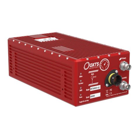
OXTS RT User manual

RT-Range Survey Trolley
Quick Start Guide

Oxford Technical Solutions Ltd www.oxts.com Page 1 of 10
Legal notices
Information furnished is believed to be accurate and reliable. However, Oxford Technical Solutions
Limited assumes no responsibility for the consequences of use of such information nor for any
infringement of patents or other rights of third parties which may result from its use. No licence is
granted by implication or otherwise under any patent or patent rights of Oxford Technical Solutions
Limited. Specifications mentioned in this publication are subject to change without notice and do not
represent a commitment on the part of Oxford Technical Solutions Limited. This publication
supersedes and replaces all information previously supplied. Oxford Technical Solutions Limited
products are not authorised for use as critical components in life support devices or systems without
express written approval of Oxford Technical Solutions Limited.
All brand names are trademarks of their respective holders.
The software is provided by the contributors “as is” and any express or implied warranties, including,
but not limited to, the implied warranties of merchantability and fitness for a particular purpose are
disclaimed. In no event shall the contributors be liable for any direct, indirect, incidental, special,
exemplary, or consequential damages (including, but not limited to, procurement of substitute goods
or services; loss of use, data, or profits; or business interruption) however caused and on any theory
of liability, whether in contract, strict liability, or tort (including negligence or otherwise) arising in any
way out of the use of this software, even if advised of the possibility of such damage.
Copyright notice
© Copyright 2021, Oxford Technical Solutions.
Contact details
Oxford Technical Solutions Limited
Park Farm Business Centre
Middleton Stoney
Oxfordshire
OX25 4AL
United Kingdom
Tel: +44 (0) 1869 814 253
Fax: +44 (0) 1869 251 764
Web: https://www.oxts.com

Oxford Technical Solutions Ltd www.oxts.com Page 2 of 10
Warranty
Oxford Technical Solutions Limited warrants its products to be free of defects in materials and
workmanship, subject to the conditions set forth below, for a period of one year from the Date of Sale.
“Date of Sale” shall mean the date of the Oxford Technical Solutions Limited invoice issued on
delivery of the product. The responsibility of Oxford Technical Solutions Limited in respect of this
warranty is limited solely to product replacement or product repair at an authorised location only.
Determination of replacement or repair will be made by Oxford Technical Solutions Limited personnel
or by personnel expressly authorised by Oxford Technical Solutions Limited for this purpose.
In no event will Oxford Technical Solutions Limited be liable for any indirect, incidental, special or
consequential damages whether through tort, contract or otherwise. This warranty is expressly in lieu
of all other warranties, expressed or implied, including without limitation the implied warranties of
merchantability or fitness for a particular purpose. The foregoing states the entire liability of Oxford
Technical Solutions Limited with respect to the products herein.
Environmental protection
Waste electrical products should not be disposed of with household waste. Please recycle where
facilities exist. Check with your Local Authority or OxTS representative for recycling advice.

Oxford Technical Solutions Ltd www.oxts.com Page 3 of 10
Contents
Legal notices .......................................................................................................................................1
Copyright notice...................................................................................................................................1
Contact details.....................................................................................................................................1
Warranty..............................................................................................................................................2
Environmental protection.....................................................................................................................2
Survey trolley ..........................................................................................................................................4
Components............................................................................................................................................5
Installation...............................................................................................................................................6
RT3000 v3 installation.........................................................................................................................9
Physical orientation: ............................................................................................................................9
Software configuration:......................................................................................................................10
Revision history.....................................................................................................................................10

Oxford Technical Solutions Ltd www.oxts.com Page 4 of 10
Survey trolley
The RT-Range Survey Trolley is an accessory which enables you to accurately survey the position of
lanes for vehicle-to-lane testing.
Figure1.SurveyTrolley

Oxford Technical Solutions Ltd www.oxts.com Page 5 of 10
Components
The components of the survey trolley are listed in Table 1.
Table1.RT-RangeSurveyTrolley components
Item
Qty
Description
1
1
Base plate with wheels attached
2
1
Lower frame assembly with radio antenna plate attached
3
1
Upper frame assembly
4
1
Fixed PC shelf
5
3
Antenna pole sections
6
2
Joint slugs
7
12
M6 × 12 mm hex socket screws
8
12
M6 washers
9
1
UNC bolt
10
2
1" U-Bolt with plate and nuts
11
1
GPS-702-GG antenna
12
4
M4 nuts
13
4
M4 × 40 mm countersunk bolt with locking nuts
14
4
M4 washers
15
2
Bungee straps
16
1
Battery connection cable
(Not shown)
1
Battery charger
(Not shown)
1
Mains cable
(Not shown)
1
Trigger switch
Please note:
Some of these components might already be pre-assembled on delivery. Item numbers refer to the
assembly drawing in Figure 2.
An adapter plate and updated config file is required to support the RT3000 v3, to ensure a secure
mount and accuracy.
The Survey Trolley will require a battery. Please note that this is not supplied by OxTS and must be
purchased by the customer. The ideal battery is a Yuasa NP24-12, a 12 V, 24 Ah lead acid battery
measuring 166 × 175 × 125 mm.

Oxford Technical Solutions Ltd www.oxts.com Page 6 of 10
Installation
The Survey Trolley has been designed to carry the RT, a battery and a laptop computer. The GPS
antenna on the Survey Trolley is sufficiently high so that there will be minimal interference from the
operator. The position measurements are displaced to the front right wheel so that this wheel can be
pushed along the road markings. The displacement will be accurate even when the Survey Trolley is
at a significant angle (e.g. on a road with a large camber).
Figure2.SurveyTrolleyassembly

Oxford Technical Solutions Ltd www.oxts.com Page 7 of 10
The RT should be set up on the Survey Trolley facing the rear and clamped down securely so it
cannot move. The installation on the Survey Trolley is shown in Figure 3.
Figure3.SurveyTrolley installation
An iron plate is provided to hold the magnetic antenna for the radio modem.
The connections for the RT on the Survey Trolley are the same as those on a vehicle and are shown
in Figure 4.
If a trigger switch is being used, then it should be connected to J5 of the RT. A trigger event can be
made by shorting the Event Input pin on J5 of the 14C0038A User Cable to ground. The trigger event
can be used to place a point in the line file for the map. A switch is provided with the Survey Trolley
with a pre-wired connector that fits on J5.

Oxford Technical Solutions Ltd www.oxts.com Page 8 of 10
Figure4.ConnectiondiagramfortheRTon theSurveyTrolley
Note: The connection is shown here with the SATEL radio option. The Freewave and other radio
options are similar.
The RT will need to be configured correctly for use on the Survey Trolley. Table 2 lists the critical
configuration parameters that should be used with the Survey Trolley. Other parameters can be left at
the default values.
Table2.RTconfigurationon thesurveytrolley
Parameter
Setting
Orientation
Default settings: y-axis right; z-axis down
Primary Antenna
Behind 0.230; left 0.075; above 1.520; overall accuracy 0.01
Dual Antenna
No
Initialisation Speed
1 m/s
Displace Output
Ahead 0.125; right 0.105; below 0.095
This configuration sets the measurement point for the survey at the centre of the wheel contact patch
for the front right wheel of the Survey Trolley. It is normally easier to survey using a wheel as a
marker rather than a point on the Survey Trolley.
A suitable configuration for the Survey Trolley is installed in the folder:
C:\Program Files (x86)\OxTS\RT-Range\Survey Trolley
This can be installed using NAVconfig.
To initialise the RT on the Survey Trolley push the Survey Trolley in a forward direction at a speed
exceeding 1 m/s. You should be going straight when the RT initialises. Afterwards you should make
some turns, accelerate and brake so that the RT can estimate some of the errors in its sensors.
The battery recommended for use with the Survey Trolley is a lead-acid battery. This should be kept
in a charged state; it should be recharged immediately after each use. Lead- acid batteries tend to
degrade if left in an uncharged state.

Oxford Technical Solutions Ltd www.oxts.com Page 9 of 10
To charge the battery, connect the charger to the battery and plug the charger into the mains. The
light on the charger will indicate green when the battery is fully charged. The charger can be left on
the battery at all times when the battery is not in use.
Lead-acid batteries require special disposal in most countries. To dispose of the battery take it to the
appropriate waste disposal place.
RT3000 v3 installation
The new RT3000 v3 is physically smaller than the RT3000 v2. To use the RT3000 v3 with the OxTS
Survey Trolley it should therefore be located on the specifically designed Acetal adapter plate to
ensure the INS remains securely in place on the Survey Trolley base plate.
When setting the RT3000 v3 physical orientation and configuration, please modify the settings to the
following found below. The pre-configured settings can also be found in your NAVsuite installation
folder; the default installation path is here:
C:\Program Files (x86)\OxTS\RT-Range\Survey Trolley\v3
If no v3 folder is present, please make sure that you are using the latest version of RT-Range. The
configuration files can be installed using NAVconfig.
Physical orientation:
1. Place the adapter plate such that it fits in the original RT3000 slot on the trolley base.
2. Place the RT3000 v3 on the adapter plate with the cables facing forwards of the trolley and attach
the retaining strap over the unit as normal.
Figure5.PlacementofAdapterplatewithRT3000v3onaSurveyTrolley

Oxford Technical Solutions Ltd www.oxts.com Page 10 of 10
Software configuration:
Only the Orientation, GNSS antenna position, and Displaced output need to be changed. Please
see the RT-Range manual for all other settings. A summary of the required changes can be seen in
Table 3.
Table3.RTConfigurationon theSurveyTrolleyChanges
Parameter
Setting
Orientation
Default settings: y-axis left; z-axis down
Primary Antenna
Behind 0.090; left 0.080; above 1.480; overall accuracy 0.01
Displaced Output
Ahead 0.26; right 0.09; below 0.12
Revision history
Table4.Revisionhistory
Revision
Comments
210429
Initial version

Oxford Technical Solutions Ltd Page 11 of 12
This manual suits for next models
1
Table of contents
Other OXTS Measuring Instrument manuals