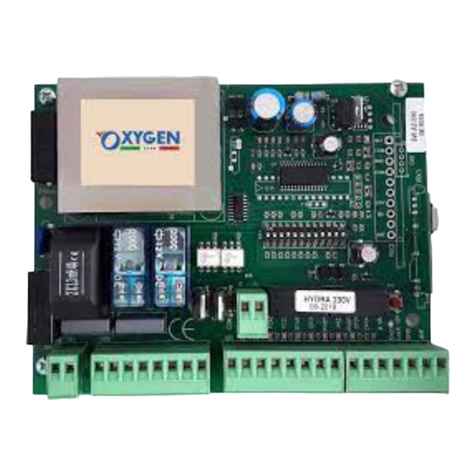
Oxygen NEREA 230V User manual

EN - NEREA 230V –DO IT YOURSELF (DIY) INSTALLATION
1) Using the Release Key, close the gate and lock the motors (or the motor in the case of a single leaf gate).
2) Connect the motors according to the diagram on the first page of the manual:
- Common (COM) is the GREY or BLUE wire.
- Opening (AP) and closing (CH) are BROWN and BLACK.
- connect the capacitor (white or black cylinder with two wires) in parallel between BROWN and BLACK (AP and CH), there is
no polarity
- connect the yellow/green wire (Ground/Earth) on any of the three available terminals of the CN1 connector
3) Supply 230V to terminals 1 and 2 of CN2 (L and N)
4) Place two jumpers on DS1 and DS2, so, between 8-9 and 9-10 of CN3 (the DS1 and DS2 LEDs must be on)
DOUBLE LEAF GATES:
5A) Remote Control buttons store:
-press the SEL button once, AUT/PP LED will start flashing.
-Press the SEL button again, and the LED CODE will start flashing.
-Press a button on the remote control - the CODE LED stays lit steady –remote control stored successfully
-Repeat with every remote control that needs to be stored.
6A) –Press the button on the remote control, the gate opens (The motor will be active and will open for 30 seconds).
- Press the remote control button again, the gate closes (The motor will be active and will close for 30 seconds).
7A) Warmly Recommended: Follow the procedure as indicated in the instruction manual (chapter 5 - T.MOT and SLOWING) in
order to set the desired times and slowdown function.
If the motors work backwards, the BROWN and BLACK wires (AP and CH) must be switched one with the other.
SINGLE LEAF GATES:
5B) Remote Control buttons store:
-Press the SEL button once and the AUT/PP LED will start flashing.
-Press the SEL button again, the LED CODE will start flashing.
-Press the SEL button again, the CODE PED LED will start flashing.
-Press a button on the remote control –the LED CODE PED will stay lit –remote control stored.
-Repeat with every remote control that needs to be stored.
6B) - Press the button on the remote control, the gate opens (The motor will be active and will open for 10 seconds).
- Press the remote control button again, the gate closes (The motor will be active and will close for 10 seconds).
7B) Warmly Recommended: : Follow the procedure as indicated in the instruction manual (chapter 6 - T.MOT PED) in order to
set the desired times and slowdown function.
8) Use a screwdriver to adjust the force trimmer to the maximum (clockwise rotation) and gradually decrease it according
to the force required to open and close the gate.
In case of necessity or incorrect setting, you can always restore the factory default values by simply pressing the SEL and SET
buttons simultaneously for a few seconds, all the LEDs in the upper right corner will light up and go out = reset successful
ACCESSORIES CONNECTIONS (depending on the purchased kit):
9) - Place the photocells on the Gate Pillars, about 50cm far from the ground, and connect them as shown in the diagram
on the first manual page.
At the end of the connection remove the jumper on DS1
- In the case of two pairs of photocells (2 Transmitters and 2 Receivers) connect the internal photocell according to the
main photocell diagram, but with the NC terminal on number 10 instead of number 8.
When finished, remove the jumper on DS2.
10) Connect a 17cm wire to terminal 12 (Antenna) only after storing the remote controls. Leave it inside the waterproof
box, there is no need to drill holes on the box or connect external antennas.
11) Connect the 230V flashing light to terminals 3 and 4 of CN2.
12) Connect the Electric Lock on terminals 3 and 4 of CN3.
If the electric lock is 12VDC (direct current), the polarity must be respected, (+12Vdc = number 3)
13) Connect all the desired opening devices, as a push button, an intercom, a key selector, etc., to terminals 5 and 6 of CN3,
in case of a single leaf gate, connect them to terminals 6 and 7,
Notice: device contacts must not be powered (clean contact)
14) The Wireless Keypad works like a remote control, follow step 5A or 5B by entering the desired code (instead of pressing
the remote control button), this way the control unit will save that code

IT - NEREA 230V - INSTALLAZIONE FAI DA TE (DIY)
1) Posizionare il cancello in chiusura e bloccare i motori (o il motore in caso di anta singola) con la chiave di sblocco
2) Collegare i motori come da schema sulla prima pagina del manuale:
- il comune (COM) è il filo GRIGIO oppure BLU
- apertura (AP) e chiusura (CH) sono MARRONE e NERO
- collegare il condensatore (cilindro bianco o nero con due fili) in parallelo tra MARRONE E NERO (AP e CH), non c’è polarità
- collegare il filo giallo/verde (terra) su un qualsiasi morsetto dei tre disponibili del connettore CN1
3) Alimentare a 230V i morsetti 1 e 2 del CN2 (L e N)
4) Posizionare due ponticelli su DS1 e DS2, cioè tra 8-9 e 9-10 del CN3 (i LED DS1 e DS2 devono essere accesi)
CANCELLO A DUE ANTE:
5A) Memorizzare il telecomando:
-premere il tasto SEL una volta e lampeggia il LED AUT/PP
-premere nuovamente il tasto SEL e lampeggia il LED CODE
-premere un tasto del telecomando –il LED CODE rimane acceso fisso - telecomando memorizzato
-ripetere l’operazione per tutti i telecomandi che desidera memorizzare
6A) - Premere il tasto del telecomando, il cancello apre (il motore è attivo in apertura per 30 secondi)
- Premere nuovamente il tasto del telecomando, il cancello chiude (il motore è attivo in chiusura per 30 secondi)
7A) Altamente consigliato: Seguire la procedura indicata nel manuale di istruzioni (capitolo 5 - T.MOT e RALLENTAMENTO) in
modo da impostare i tempi desiderati ed il rallentamento
Se i motori lavorano al contrario, occorre invertire i fili marrone e nero (AP e CH)
CANCELLO AD UN’ANTA:
5B) Memorizzare il telecomando:
-premere il tasto SEL una volta e lampeggia il LED AUT/PP
-premere nuovamente il tasto SEL e lampeggia il LED CODE
-premere nuovamente il tasto SEL e lampeggia il LED CODE PED
-premere un tasto del telecomando –il LED CODE PED rimane acceso fisso - telecomando memorizzato
-ripetere l’operazione per tutti i telecomandi che desidera memorizzare
6B) - Premere il tasto del telecomando, il cancello apre (il motore è attivo in apertura per 10 secondi)
- Premere nuovamente il tasto del telecomando, il cancello chiude (il motore è attivo in chiusura per 10 secondi)
7B) Altamente consigliato: Seguire la procedura indicata nel manuale di istruzioni (capitolo 6 T.MOT PED) in modo da impostare i
tempi corretti ed il rallentamento
8) Regolare con il cacciavite il trimmer della forza al massimo (senso orario) e, diminuirlo piano piano a seconda della forza
necessaria per aprire e chiudere il cancello
In caso di difficoltà o errata impostazione, è sempre possibile ripristinare i valori di fabbrica, semplicemente premendo i tasti
SEL e SET contemporaneamente per qualche secondo, tutti i LED in alto a destra si accendono e si spengono = reset effettuato
COLLEGAMENTO ACCESSORI (se presenti a seconda del kit acquistato):
9) - Posizionare le fotocellule sui pilastri, a circa 50cm da terra, e collegarle come da schema in prima pagina.
Al termine del collegamento rimuovere il ponticello su DS1
-In caso di due coppie di fotocellule (2 Trasmittenti e 2 Riceventi) collegare la fotocellula interna come da schema della
fotocellula principale, ma con il morsetto NC sul numero 10 invece che sul numero 8.
Al termine del collegamento rimuovere il ponticello su DS2
10) Collegare un cavetto di 17cm sul morsetto 12 (Antenna) solamente dopo aver memorizzato i telecomandi. Lasciarlo
all’interno della scatola stagna, non occorre forare la scatola o collegare antenne esterne
11) Collegare il lampeggiante a 230V sui morsetti 3 e 4 del CN2
12) Collegare l’elettroserratura sui morsetti 3 e 4 del CN3
Se la serratura è in 12V continua, occorre rispettare la polarità, (+12Vdc = numero 3)
13) Collegare tutti i dispositivi di comando desiderati, per esempio un pulsante, un citofono, un selettore a chiave, ecc.. sui
morsetti 5 e 6 del CN3, in caso di cancello ad un’anta collegarli sul 6 e 7,
Importante: i contatti dei dispositivi non devono essere alimentati (contatto pulito)
14) Il Tastierino wireless funziona come un telecomando, seguire il punto 5A o 5B inserendo il codice desiderato (invece di
premere il tasto del telecomando) in questo modo la scheda salverà tale codice

FR - NEREA 230V - INSTALLATION À FAIRE VOUS-MÊME
1) Fermez le portail et verrouiller les moteurs (ou le moteur dans le cas d'un portail à un battant) avec la clé de déverrouillage.
2) Connectez les moteurs selon le schéma de la première page du manuel:
- Le fil commun (COM) est le fil GRIS ou BLEU.
-L'ouverture (AP) et la fermeture (CH) sont MARRON et NOIR.
- connectez le condensateur (cylindre blanc ou noir avec deux fils) en parallèle entre MARRON et NOIR (AP et CH), il n'y a
pas de polarité
- connectez le fil jaune / vert (Terre) sur l'une des trois bornes disponibles du connecteur CN1
3) Alimentez à 230V les bornes 1 et 2 du CN2 (L et N)
4) Placez deux cavaliers sur DS1 et DS2, donc, entre 8-9 et 9-10 de CN3 (les LED DS1 et DS2 doivent être allumées)
PORTAILS À DOUBLE VANTAIL:
5A) Mémorisez la télécommande:
-appuyez une fois sur le bouton SEL, la LED AUT / PP commencera à clignoter.
-Appuyez à nouveau sur le bouton SEL et le LED CODE commencera à clignoter.
-Appuyez sur un bouton de la télécommande-la LED CODE reste allumée fixe- la télécommande a été mémorisée
-répétez l'opération pour toutes les télécommandes que vous souhaitez mémoriser
6A) - Appuyez sur le bouton de la télécommande, le portail s'ouvre (le moteur sera actif et s'ouvrira pendant 30 secondes).
- Appuyez à nouveau sur le bouton de la télécommande, le portail se ferme (le moteur sera actif et se fermera pendant 30
secondes).
7A) Chaudement recommandé: Suivre la procédure indiquée dans le manuel d'instructions (chapitre 5 - T. MOT et
RALENTISSEMENT) afin de régler les temps et la fonction de ralentissement souhaités.
Si les moteurs fonctionnent à l'envers, les fils MARRON et NOIR (AP et CH) doivent être commutés l'un avec l'autre.
PORTES À VANTAIL UNIQUE:
5B) Mémorisez la télécommande:
-Appuyez une fois sur le bouton SEL et la LED AUT / PP commencera à clignoter.
-Appuyez à nouveau sur le bouton SEL, le LED CODE commencera à clignoter.
-Appuyez à nouveau sur la touche SEL, la LED CODE PED commencera à clignoter.
-Appuyez sur un bouton de la télécommande - la LED CODE PED reste allumée - la télécommande est mémorisée.
-répétez l'opération pour toutes les télécommandes que vous souhaitez mémoriser
6B) - Appuyez sur le bouton de la télécommande, le portail s'ouvre (le moteur sera actif et s'ouvrira pendant 10 secondes).
- Appuyez à nouveau sur le bouton de la télécommande, le portail se ferme (le moteur sera actif et se fermera pendant 10 secondes).
7B) Chaudement recommandé: Suivez la procédure indiquée dans le manuel d'instructions (chapitre 6 - T.MOT PED) afin de
régler les temps et la fonction de ralentissement souhaités.
8) Utilisez un tournevis pour régler le coupe-bordures au maximum (rotation dans le sens des aiguilles d'une montre) et
diminuez-le progressivement en fonction de la force requise pour ouvrir et fermer le portail.
En cas de difficulté ou de réglage incorrect, il est toujours possible de restaurer les valeurs d'usine en appuyant simplement sur les touches
SEL et SET simultanément pendant quelques secondes, toutes les LED en haut à droite s'allument et s'éteignent = réinitialisation effectuée
RACCORDEMENT DES ACCESSOIRES (si présent en fonction du kit acheté):
9) - Placez les photocellules sur les piliers du portail, à environ 50 cm du sol, et connectez-les comme indiqué sur le
schéma de la première page de manuel.
À la fin de la connexion, retirez le cavalier sur DS1
- Dans le cas de deux paires de photocellules (2 émetteurs et 2 récepteurs) connecter la photocellule interne selon le
schéma de la photocellule principale, mais avec la borne NC sur le numéro 10 au lieu du numéro 8.
Lorsque vous avez terminé, retirez le cavalier sur DS2.
10) Connectez un fil de 17 cm à la borne 12 (Antenne) uniquement après avoir rangé les télécommandes. Laissez-le à
l'intérieur de la boîte étanche, il n'est pas nécessaire de percer des trous sur la boîte ou de connecter des antennes
externes.
11) Connectez le clignotant 230V aux bornes 3 et 4 de CN2.
12) Connectez la serrure électrique aux bornes 3 et 4 de CN3.
Si la serrure électrique est de 12VDC (courant continu), la polarité doit être respectée, (+ 12Vdc = numéro 3)
13) Connecter tous les dispositifs d'ouverture souhaités, comme un bouton, un interphone, un sélecteur à clé, etc., aux
bornes 5 et 6 de CN3, dans le cas d'un portail à un battant, les connecter aux bornes 6 et 7,
Remarque: les contacts de l'appareil ne doivent pas être alimentés (contact propre)
14) Le petit clavier sans fil fonctionne comme une télécommande, suivez l'étape 5A ou 5B en entrant le code souhaité (au
lieu d'appuyer sur le bouton de la télécommande), de cette façon, l'unité de contrôle enregistrera ce code

DE - NEREA 230V –SELBERMACHEN (DIY)
1) Schließen Sie das Tor, und verriegeln Sie die Motoren (oder den Motor bei einem einflügeligen Tor) mit dem
Entriegelungsschlüssel. Schließen Sie die Motoren gemäß der Abbildung auf der ersten Seite des Handbuchs an:
2) - Common (COM) ist der graue oder blaue Draht.
- Öffnen (AP) und Schließen (CH) sind BRAUN und SCHWARZ.
- Verbinden Sie den Kondensator (weißer oder schwarzer Zylinder mit zwei Drähten) parallel zwischen BRAUN und
SCHWARZ (AP und CH), es gibt keine Polarität
- Schließen Sie das gelb / grüne Kabel (Masse / Erde) an eine der drei verfügbaren Klemmen des CN1-Steckers an
3) Versorgen Sie Die Klemmen 1 und 2 von CN2 (L und N) mit 230 V
4) Platzieren Sie zwei Jumper auf DS1 und DS2, also zwischen 8-9 und 9-10 von CN3 (die LEDs DS1 und DS2 müssen
leuchten).
Zweiflügel Töre :
5A) Fernbedienungstasten speichern:
-Drücken Sie die SEL-Taste einmal. Die AUT / PP-LED beginnt zu blinken
-Drücken Sie die SEL-Taste erneut und der LED-CODE beginnt zu blinken.
-Drücken Sie eine Taste auf der Fernbedienung - die CODE-LED leuchtet konstant - die Fernbedienung wurde erfolgreich
gespeichert
-Wiederholen Sie dies mit jeder Fernbedienung, die gespeichert werden muss.
6A) - Drücken Sie die Taste auf der Fernbedienung, das Tor öffnet sich (Der Motor ist aktiv und öffnet sich 30 Sekunden lang).
-Drücken Sie die Fernbedienungstaste erneut, das Tor schließt sich (der Motor ist aktiv und schließt 30 Sekunden lang).
7A) Wärmstens empfohlen: Befolgen Sie die Anweisungen in der Bedienungsanleitung (Kapitel 5 - T.MOT und SLOWING), um
die gewünschten Zeiten und die Verlangsamungsfunktion einzustellen.
Wenn die Motoren rückwärts arbeiten, müssen die BRAUNEN und SCHWARZEN Drähte (AP und CH) geschaltet werden.
Ein-Flüglel Töre
5B) Fernbedienungstasten speichern:
-Drücken Sie die SEL-Taste einmal und die AUT / PP-LED beginnt zu blinken.
-Drücken Sie die SEL-Taste erneut, der LED-CODE beginnt zu blinken.
-Drücken Sie die SEL-Taste erneut, die CODE PED-LED beginnt zu blinken.
-Drücken Sie eine Taste auf der Fernbedienung - die LED CODE PED leuchtet weiter - die Fernbedienung ist gespeichert.
-Wiederholen Sie dies mit jeder Fernbedienung, die gespeichert werden muss
6B) Sie die Taste auf der Fernbedienung, das Tor öffnet sich (Der Motor ist aktiv und öffnet sich für 10 Sekunden).
- Drücken Sie die Fernbedienungstaste erneut, das Tor schließt sich (der Motor ist aktiv und schließt für 10 Sekunden).
7B) Wärmstens empfohlen: Befolgen Sie die Anweisungen in der Bedienungsanleitung (chapter 6 - T.MOT PED), um die
gewünschten Zeiten und die Verlangsamungsfunktion einzustellen.
8) Stellen Sie den Krafttrimmer mit einem Schraubendreher auf das Maximum (Drehung im Uhrzeigersinn) ein und
verringern Sie ihn schrittweise entsprechend der zum Öffnen und Schließen des Tors erforderlichen Kraft.
Bei Bedarf oder falscher Einstellung können Sie die werkseitigen Standardwerte jederzeit wiederherstellen, indem Sie einfach einige Sekunden lang
gleichzeitig die Tasten SEL und SET drücken. Alle LEDs in der oberen rechten Ecke leuchten auf und erlöschen = erfolgreich zurückgesetzt
ZUBEHÖRANSCHLÜSSE (abhängig vom gekauften Kit):
9) -Platzieren Sie die Fotozellen auf den Torsäulen, etwa 50 cm vom Boden entfernt, und schließen Sie sie wie in der
Abbildung auf der ersten Handbuchseite gezeigt an.
Entfernen Sie am Ende der Verbindung den Jumper am DS1.
-Bei zwei Fotozellenpaaren (2 Sender und 2 Empfänger) wird die interne Fotozelle gemäß dem Haupt-
Fotozellendiagramm angeschlossen, jedoch mit dem NC-Anschluss an Nummer 10 anstelle von Nummer 8.
Wenn Sie fertig sind, entfernen Sie den Jumper am DS2.
10) Schließen Sie ein 17-cm-Kabel erst nach Aufbewahrung der Fernbedienungen an Klemme 12 (Antenne) an. Lassen Sie es
in der wasserdichten Box, es ist nicht erforderlich, Löcher in die Box zu bohren oder externe Antennen anzuschließen.
11) Schließen Sie das 230-V-Blinklicht an die Klemmen 3 und 4 von CN2 an.
12) Schließen Sie das elektrische Schloss an die Klemmen 3 und 4 von CN3 an Wenn die elektrische Verriegelung 12 VDC
(Gleichstrom) beträgt, muss die Polarität eingehalten werden (+12VDC=Nummer3).
13) Sie alle gewünschten Öffnungsvorrichtungen als Druckknopf, Gegensprechanlage, Schlüsselwahlschalter usw. an die
Klemmen 5 und 6 von CN3 an. Schließen Sie sie bei einem Einzelblatt-Tor an die Klemmen 6 und 7 an.
Hinweis: Gerätekontakte dürfen nicht mit Strom versorgt werden (sauberer Kontakt).
14) Die drahtlose Tastatur funktioniert wie eine Fernbedienung. Befolgen Sie die Schritte 5A oder 5B, indem Sie den
gewünschten Code eingeben (anstatt die Fernbedienungstaste zu drücken). Auf diese Weise speichert die Steuereinheit
diesen Code.
This manual suits for next models
1
Table of contents
Languages:
Other Oxygen Control Unit manuals
Popular Control Unit manuals by other brands

Roger Technology
Roger Technology H70/104AC Instruction and warnings for the installer

rada
rada 566 Installation and Maintenance

indie
indie iND83405 Quick start user guide

Volth
Volth ARGO HYTOS PRM2X2-06 operating instructions

A.R.I.
A.R.I. Eliptix R-30 S 2W Installation, Operating, Maintenance

FrSky
FrSky FWTM instruction manual