1General Information
2018/06 99423x063MGK7-mub-en –V01 3
Contents
1General Information.........................................................................................................4
1.1 Scope of these instructions .......................................................................................... 4
1.2 Designated use ............................................................................................................ 4
2Safety instructions ...........................................................................................................5
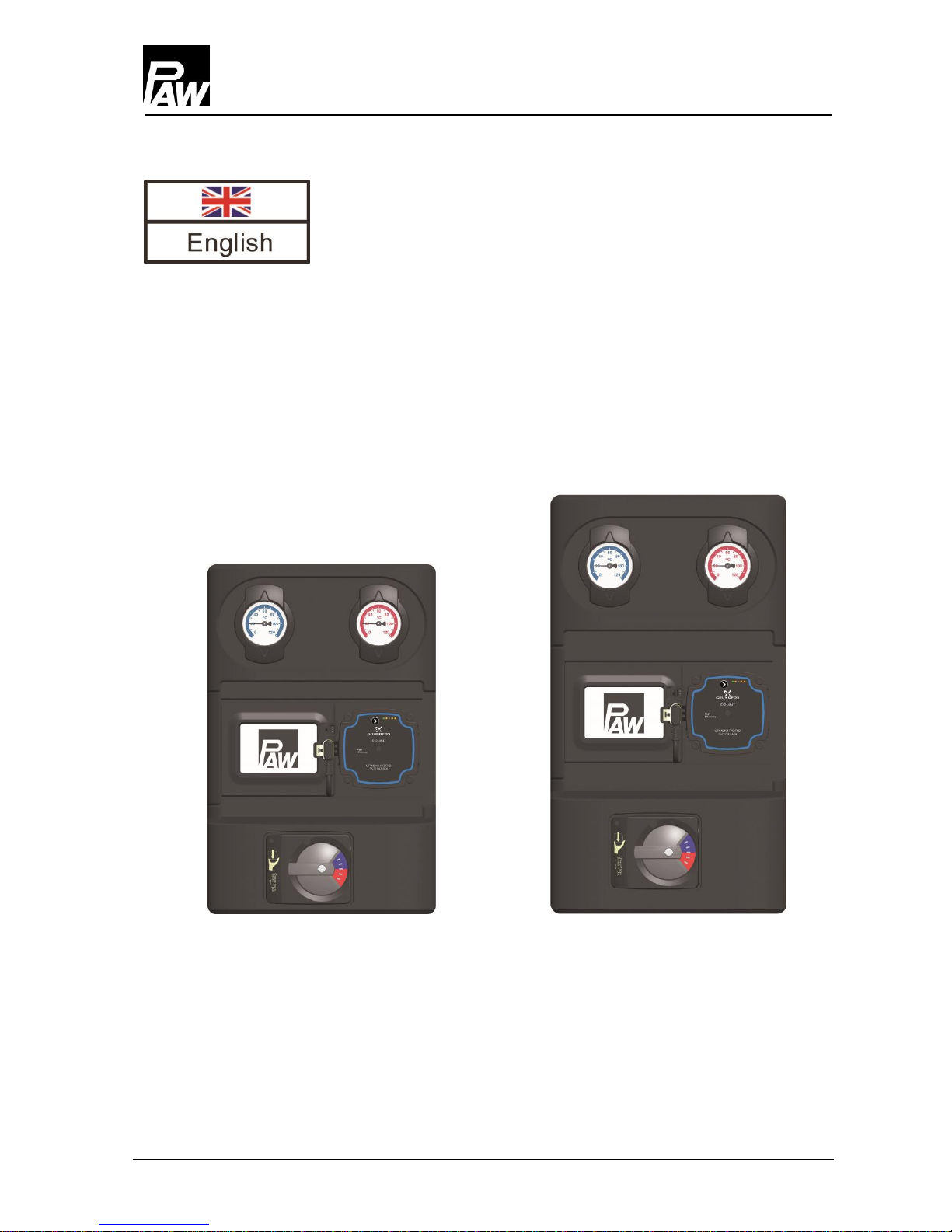
3Product description..........................................................................................................6
3.1 Equipment.................................................................................................................... 6
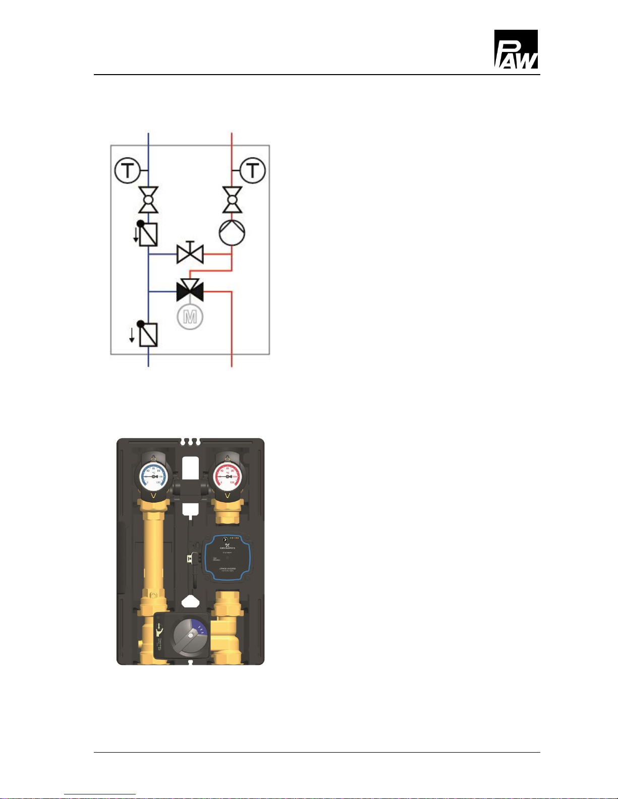
3.2 Function ....................................................................................................................... 7
3.2.1 Check valve and non-return valve ......................................................................... 8
3.2.2 Pump [specialist]................................................................................................... 9
3.2.3 3-way mixing valve [specialist] .............................................................................. 9
4Assembly and installation [specialist]..............................................................................13
4.1 Installation and commissioning of the CoolBloC......................................................... 13
4.2 Actuator...................................................................................................................... 16
4.3 Assembly of the actuator for CoolBloC with flow on the right:..................................... 16
4.4 Assembly of the actuator for CoolBloC with flow on the left:....................................... 17
5Scope of delivery [specialist]..........................................................................................18
5.1 Spare parts DN 25 ..................................................................................................... 18
5.2 Spare parts DN 32 ..................................................................................................... 19
6Technical data...............................................................................................................20
6.1 Pressure drop and pump characteristic curve C34 - DN 25 / DN 32 ........................... 21
6.2 Determination of the dew point................................................................................... 22