Permeation Chamber User’s Manual
Page 2
2.0 How it Works
The information contained in the following subsections is provided to “demystify” OTR
analysis. Your understanding of the method and the instrumentation will greatly increase
the ease of producing a valid OTR result.
2.1 Instrumentation
Using an OxySense® instrument, one is able to obtain non-invasive (i.e. in-situ) oxygen
concentration measurements by way of fluorescence quenching analysis, where, an
optical, oxygen-selective sensor (e.g. an OxyDot®) resides within a sealed container,
affixed to a transparent surface. The instrument is capable of capturing the optical signal
from the sensor and transducing the signal in to an oxygen concentration.
The OxyPerm® Permeation Chamber is equipped with an OxyDot® that resides within the
chamber, opposite a transparent reading window. An OxySense® 5000 series instrument is
used to capture an oxygen concentration reading from the sensor without disturbing the
integrity of the chamber. The space where the OxyDot® resides is isolated from the
oxygen-containing atmosphere by the material being analyzed.
2.2 Dynamic Accumulation
OxySense employs the principle of dynamic accumulation (DA) for OTR determination,
where oxygen gas that permeates through the material gradually accumulates within a
container. OxySense® instrumentation, which is ideal for the in-situ measurement of
oxygen accumulation, is used to record the increasing oxygen concentration within that
container over time. The OTR is then calculated from the oxygen accumulation data.
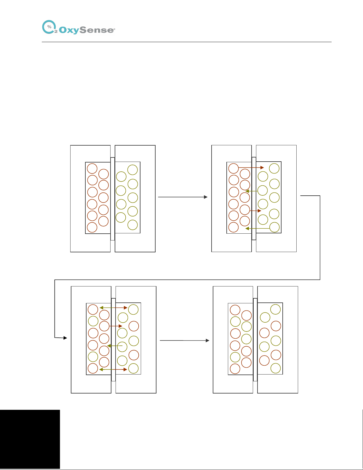
2.3 Film Permeation Tests
When determining OTR by DA using the OxyPerm® permeation chamber, the portion of the
chamber where the OxyDot® resides, called the sensing well, is first purged with an inert
gas (i.e. nitrogen) rendering the volume surrounding the sensor free of oxygen. The portion
of the well opposite the sensing well is called the driving well, the volume of which is filled
by an oxygen-containing gas (e.g. pure oxygen or air).
As gas crosses from the driving well through the film and in to sensing well, the oxygen
concentration rises. Data is captured periodically over time. The recorded oxygen
concentration and time data is then used to calculate the OTR as the oxygen and time
data are both directly correlated to the permeability of the film.
Copyright © Industrial Physics Product Integrity 2020