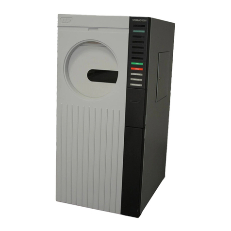
ASP STERRAD 100 User manual

STERRAD100 Sterilization System
Service Guide
Advanced Sterilization Products
33 Technology
Irvine, California 92618
1-888-STERRAD
TS-02859-0-002 REV D
This guide contains information on servicing the STERRAD®100 S Sterilizer. The
STERRAD 100 S Sterilizer is for international use only. No use other than testing related
to the development and submission of information to the FDA is authorized in the
United States.

1997 Advanced Sterilization Products Services, Inc. All rights reserved ALLIANCESM Service
Program is a registered service mark of Advanced Sterilization Products Services, Inc. Other
products mentioned in this publication are trademarked by their respective corporations.
Reproduction, adaptation or translation of this publication without prior written permission is
prohibited. Printed in the USA.

CONTENTS
CHAPTER 1. About the Service Guide
Introduction . . . . . . . . . . . . . . . . . . . . . . . . . . . . 1-2
What's New in this Guide? . . . . . . . . . . . . . . . . . . . . 1-2
New for REV D! . . . . . . . . . . . . . . . . . . . . . . . . . . . 1-2
Revision C Information . . . . . . . . . . . . . . . . . . . . . . 1-3
REV A/B Information . . . . . . . . . . . . . . . . . . . . . . . . 1-3
What's New Table? . . . . . . . . . . . . . . . . . . . . . . . . 1-4
CHAPTER 2. System Operation
Introduction . . . . . . . . . . . . . . . . . . . . . . . . . . . . 2-2
Theory of Operation-Overview . . . . . . . . . . . . . . . . . . 2-2
Routine Maintenance . . . . . . . . . . . . . . . . . . . . . . 2-3
Canceled Cycles . . . . . . . . . . . . . . . . . . . . . . . . . 2-10
Alarm Limits By Parameter . . . . . . . . . . . . . . . . . . . . 2-11
Software Overview . . . . . . . . . . . . . . . . . . . . . . . . 2-13
User Interface and Operator Controls . . . . . . . . . . . . . . 2-16
Functional Subsystems . . . . . . . . . . . . . . . . . . . . . . 2-16
Additional Documentation . . . . . . . . . . . . . . . . . . . . 2-17
STERRAD 100 S Theory of Operation . . . . . . . . . . . . . . . 2-18
Introduction . . . . . . . . . . . . . . . . . . . . . . . . . . . . 2-18
Phase 1 - Vacuum Preconditioning . . . . . . . . . . . . . . . 2-18
Phase 2 - Sterilization A . . . . . . . . . . . . . . . . . . . . . . 2-19
Phase 3 - Sterilization B . . . . . . . . . . . . . . . . . . . . . . 2-20
Phase 4 - Venting . . . . . . . . . . . . . . . . . . . . . . . . . 2-21
STERRAD 100 S Process Times . . . . . . . . . . . . . . . . . . . 2-21
CHAPTER 3. System Messages
Introduction . . . . . . . . . . . . . . . . . . . . . . . . . . . . 3-2
Using System Messages . . . . . . . . . . . . . . . . . . . . . . 3-2
CHAPTER 4. Vacuum Subsystem
Introduction . . . . . . . . . . . . . . . . . . . . . . . . . . . . 4-2
Different Subsystem Configurations . . . . . . . . . . . . . . . 4-2
Theory of Operation . . . . . . . . . . . . . . . . . . . . . . . . 4-3
Vacuum Pump . . . . . . . . . . . . . . . . . . . . . . . . . . 4-3
Exhaust Filter . . . . . . . . . . . . . . . . . . . . . . . . . . . . 4-4
Oil Return Valve . . . . . . . . . . . . . . . . . . . . . . . . . . 4-4
ASP Service Guide rev. D STERRAD® 100 Sterilizer i-iii

Throttle Valve . . . . . . . . . . . . . . . . . . . . . . . . . . . 4-4
Pump Intake Filter . . . . . . . . . . . . . . . . . . . . . . . . . 4-4
HEPA Filter . . . . . . . . . . . . . . . . . . . . . . . . . . . . . 4-4
Vent Valve . . . . . . . . . . . . . . . . . . . . . . . . . . . . . 4-5
Pressure Switch . . . . . . . . . . . . . . . . . . . . . . . . . . 4-5
Capacitance Manometer . . . . . . . . . . . . . . . . . . . . 4-5
Vacuum Subsystem Calibration . . . . . . . . . . . . . . . . . 4-5
Adjusting The Vacuum Switch . . . . . . . . . . . . . . . . . . 4-6
Vacuum Switch Test- Block 2 . . . . . . . . . . . . . . . . . . . 4-6
Adjustments and Settings . . . . . . . . . . . . . . . . . . . . . 4-7
Vacuum Pump Ballast Valve Adjustments . . . . . . . . . . . 4-7
Removal/Replacement Procedures . . . . . . . . . . . . . . . 4-8
Pre-Removal Procedures . . . . . . . . . . . . . . . . . . . . . 4-8
Remove the Bellows . . . . . . . . . . . . . . . . . . . . . . . 4-8
Remove the Throttle Valve . . . . . . . . . . . . . . . . . . . . 4-8
Remove the Vacuum Switch . . . . . . . . . . . . . . . . . . 4-8
Remove the Vent Valve . . . . . . . . . . . . . . . . . . . . . 4-10
Remove the HEPA Filter . . . . . . . . . . . . . . . . . . . . . 4-10
Remove the Intake Filter . . . . . . . . . . . . . . . . . . . . . 4-10
Remove the Exhaust Filter . . . . . . . . . . . . . . . . . . . . 4-10
Remove the AC Connection . . . . . . . . . . . . . . . . . . 4-10
Remove the Drain Valve . . . . . . . . . . . . . . . . . . . . . 4-10
Remove the Oil Return Valve . . . . . . . . . . . . . . . . . . 4-11
Remove the Pump . . . . . . . . . . . . . . . . . . . . . . . . 4-11
Replacement Set-Up . . . . . . . . . . . . . . . . . . . . . . . 4-11
Attaching the Pump . . . . . . . . . . . . . . . . . . . . . . . 4-13
Replace the HEPA filter . . . . . . . . . . . . . . . . . . . . . . 4-13
Replace the Intake Filter . . . . . . . . . . . . . . . . . . . . . 4-13
Replace the Throttle Valve . . . . . . . . . . . . . . . . . . . . 4-13
Replace the Bellows . . . . . . . . . . . . . . . . . . . . . . . 4-14
Replace the Vacuum Switch . . . . . . . . . . . . . . . . . . 4-14
Replace the Vent Valve . . . . . . . . . . . . . . . . . . . . . 4-14
Replace the Exhaust Filter . . . . . . . . . . . . . . . . . . . . 4-14
Replace the Oil Return Valve . . . . . . . . . . . . . . . . . . 4-14
Attaching the Power Cables . . . . . . . . . . . . . . . . . . . 4-14
CHAPTER 5. Injection Subsystem
Introduction . . . . . . . . . . . . . . . . . . . . . . . . . . . . 5-2
Different Injection Subsystem Configurations . . . . . . . . . . 5-2
Theory of Operation-Injection Subsystem . . . . . . . . . . . . 5-2
Cassettes . . . . . . . . . . . . . . . . . . . . . . . . . . . . . . 5-3
Error Handling . . . . . . . . . . . . . . . . . . . . . . . . . . . 5-4
i-iv STERRAD® 100 Sterilizer ASP Service Guide rev. D

Power Failure . . . . . . . . . . . . . . . . . . . . . . . . . . . 5-4
Injection Subsystem Calibration . . . . . . . . . . . . . . . . . 5-4
Injector Valve Height . . . . . . . . . . . . . . . . . . . . . . . 5-4
Injector Valve Height-Block 2 . . . . . . . . . . . . . . . . . . 5-5
Injector Pump Valve Adjustment . . . . . . . . . . . . . . . . 5-5
Cassette Optics . . . . . . . . . . . . . . . . . . . . . . . . . . 5-6
Injector Pump Floating Guide Adjustment . . . . . . . . . . . 5-7
Injector Pump Pneumatics . . . . . . . . . . . . . . . . . . . . 5-8
Injection Subsystem Removal/Replacement . . . . . . . . . . 5-9
Pre-Removal Procedures . . . . . . . . . . . . . . . . . . . . . 5-9
Remove the Injector Pump . . . . . . . . . . . . . . . . . . . . 5-9
Replace the Injector Pump . . . . . . . . . . . . . . . . . . . 5-9
Remove the Injector Valve . . . . . . . . . . . . . . . . . . . . 5-11
Block 2 Injector Valve/Vaporizer Removal . . . . . . . . . . . 5-12
Replace the Injector Valve . . . . . . . . . . . . . . . . . . . 5-12
CHAPTER 6. User Interface and Control Subsystems
Introduction . . . . . . . . . . . . . . . . . . . . . . . . . . . . 6-2
Different User Subsystem Configurations . . . . . . . . . . . . 6-2
Different Controller Configurations . . . . . . . . . . . . . . . . 6-2
Theory of Operation . . . . . . . . . . . . . . . . . . . . . . . 6-3
User Interface Subsystem . . . . . . . . . . . . . . . . . . . . . 6-4
Controller Operation . . . . . . . . . . . . . . . . . . . . . . . 6-7
User Interface Calibration . . . . . . . . . . . . . . . . . . . . . 6-10
Setting the Printer DIP Switches . . . . . . . . . . . . . . . . . 6-11
Setting the Audible Alarm . . . . . . . . . . . . . . . . . . . . 6-12
Setting the LCD Contrast . . . . . . . . . . . . . . . . . . . . . 6-12
Setting System Parameters . . . . . . . . . . . . . . . . . . . . 6-12
Setting the System Clock . . . . . . . . . . . . . . . . . . . . . 6-16
Setting the System Serial Number and Total Machine Cycles . 6-17
Master Reset . . . . . . . . . . . . . . . . . . . . . . . . . . . . 6-18
Controller Calibration . . . . . . . . . . . . . . . . . . . . . . . 6-19
Power Supply Adjustment . . . . . . . . . . . . . . . . . . . . 6-19
Analog To Digital (Set Point) . . . . . . . . . . . . . . . . . . . 6-21
High/Low Pressure Range Divider Voltage . . . . . . . . . . . 6-22
User Subsystem Replacement Procedures . . . . . . . . . . . 6-22
Remove/Replace the Printer . . . . . . . . . . . . . . . . . . . 6-22
Remove/Replace the Printer (Block 2) . . . . . . . . . . . . . 6-23
Remove/Replace the Membrane Switch . . . . . . . . . . . . 6-23
Control Subsystem Replacement . . . . . . . . . . . . . . . . 6-24
Remove the Control Enclosure . . . . . . . . . . . . . . . . . 6-24
Replace the Control Enclosure . . . . . . . . . . . . . . . . . 6-25
ASP Service Guide rev. D STERRAD® 100 Sterilizer i-v

Remove the Power Supplies . . . . . . . . . . . . . . . . . . . 6-25
Replace the Power Supplies . . . . . . . . . . . . . . . . . . . 6-25
Remove/Replace the Firmware . . . . . . . . . . . . . . . . . 6-26
CHAPTER 7. Door and Chamber Subsystem
Contents . . . . . . . . . . . . . . . . . . . . . . . . . . . . . . 7-1
Introduction . . . . . . . . . . . . . . . . . . . . . . . . . . . . 7-2
Different Door and Chamber Configurations . . . . . . . . . . 7-2
Door and Chamber Subsystem Descriptions . . . . . . . . . . 7-2
Door and Chamber Theory of Operation . . . . . . . . . . . . 7-3
Chamber Subsystem . . . . . . . . . . . . . . . . . . . . . . . 7-3
Door Subsystem . . . . . . . . . . . . . . . . . . . . . . . . . . 7-3
Calibration . . . . . . . . . . . . . . . . . . . . . . . . . . . . . 7-4
Door and Chamber Temperature . . . . . . . . . . . . . . . . 7-4
Door Top, Bottom, And Over Center Sensors . . . . . . . . . . 7-6
Door Open Close Speed . . . . . . . . . . . . . . . . . . . . . 7-6
Door and Chamber Alignment . . . . . . . . . . . . . . . . . 7-7
Removal/Replacement . . . . . . . . . . . . . . . . . . . . . . 7-13
Open The Door For Servicing . . . . . . . . . . . . . . . . . . . 7-13
Remove the Electrode and Spacers . . . . . . . . . . . . . . 7-13
Replace the Electrode and Spacers . . . . . . . . . . . . . . 7-14
Remove/Replace the Door . . . . . . . . . . . . . . . . . . . 7-15
Chamber Heaters Removal/Replacement . . . . . . . . . . . 7-18
Remove/Replace the Feedthrough . . . . . . . . . . . . . . . 7-23
Remove the Sight Glass . . . . . . . . . . . . . . . . . . . . . 7-27
Replace the Sight Glass . . . . . . . . . . . . . . . . . . . . . 7-27
CHAPTER 8. Pneumatic Subsystem
Introduction . . . . . . . . . . . . . . . . . . . . . . . . . . . . 8-2
Different Pneumatic Configurations . . . . . . . . . . . . . . . 8-2
Pneumatic Subsystem Description . . . . . . . . . . . . . . . . 8-2
Pneumatic Theory of Operation . . . . . . . . . . . . . . . . . 8-2
Pneumatics Calibration . . . . . . . . . . . . . . . . . . . . . . 8-3
Pneumatics Pressure Switch . . . . . . . . . . . . . . . . . . . 8-3
Pneumatics Removal/Replacement Procedures . . . . . . . 8-5
CHAPTER 9. AC Subsystem
Introduction . . . . . . . . . . . . . . . . . . . . . . . . . . . . 9-2
Different AC Configurations . . . . . . . . . . . . . . . . . . . 9-2
AC Subsystem Theory of Operation . . . . . . . . . . . . . . . 9-2
AC Calibration . . . . . . . . . . . . . . . . . . . . . . . . . . . 9-2
AC Removal/Replacement . . . . . . . . . . . . . . . . . . . 9-3
i-vi STERRAD® 100 Sterilizer ASP Service Guide rev. D

Remove the AC Enclosure . . . . . . . . . . . . . . . . . . . . 9-4
Replace the AC Enclosure . . . . . . . . . . . . . . . . . . . . 9-5
Remove the Solid State Relay Board . . . . . . . . . . . . . . 9-5
Replace the Solid State Relay Board . . . . . . . . . . . . . . 9-5
CHAPTER 10. Radio Frequency (RF) Subsystem
Introduction . . . . . . . . . . . . . . . . . . . . . . . . . . . . 10-2
Different RF Configurations . . . . . . . . . . . . . . . . . . . . 10-2
RF Theory of Operation . . . . . . . . . . . . . . . . . . . . . . 10-2
RF Calibration . . . . . . . . . . . . . . . . . . . . . . . . . . . 10-4
RF Removal/Replacement . . . . . . . . . . . . . . . . . . . . 10-4
Remove the RF Enclosure . . . . . . . . . . . . . . . . . . . . 10-4
Remove the RF Match . . . . . . . . . . . . . . . . . . . . . . 10-4
CHAPTER 11. System Installation
Introduction . . . . . . . . . . . . . . . . . . . . . . . . . . . . 11-2
Pre-Installation . . . . . . . . . . . . . . . . . . . . . . . . . . . 11-2
Uncrating the System . . . . . . . . . . . . . . . . . . . . . . . 11-3
Power Connection . . . . . . . . . . . . . . . . . . . . . . . . 11-8
Installing the Seismic Restraints . . . . . . . . . . . . . . . . . . 11-9
Pre-Installation Procedure-To Be Done by the Customer . . . 11-9
Installing the Subframe . . . . . . . . . . . . . . . . . . . . . . 11-10
Installing the Brackets . . . . . . . . . . . . . . . . . . . . . . . 11-11
Preparing The System For Use . . . . . . . . . . . . . . . . . . . 11-12
Phase Rotation . . . . . . . . . . . . . . . . . . . . . . . . . . 11-12
Initialization . . . . . . . . . . . . . . . . . . . . . . . . . . . . 11-13
Master Resets . . . . . . . . . . . . . . . . . . . . . . . . . . . 11-13
Cassette Collector Box . . . . . . . . . . . . . . . . . . . . . . 11-14
Date and Time . . . . . . . . . . . . . . . . . . . . . . . . . . 11-14
PM Log . . . . . . . . . . . . . . . . . . . . . . . . . . . . . . . 11-15
System Acceptance . . . . . . . . . . . . . . . . . . . . . . . 11-15
International System Configurations . . . . . . . . . . . . . . . 11-16
Attach Machine Label . . . . . . . . . . . . . . . . . . . . . . 11-16
Thermal Overload Relay . . . . . . . . . . . . . . . . . . . . . 11-17
Power Plug . . . . . . . . . . . . . . . . . . . . . . . . . . . . . 11-18
Control Panel Bezel . . . . . . . . . . . . . . . . . . . . . . . . 11-18
Software Installation . . . . . . . . . . . . . . . . . . . . . . . 11-18
System Reset . . . . . . . . . . . . . . . . . . . . . . . . . . . . 11-19
Verify Voltages . . . . . . . . . . . . . . . . . . . . . . . . . . 11-19
ASP Service Guide rev. D STERRAD® 100 Sterilizer i-vii

Install Printer Ribbon and Paper . . . . . . . . . . . . . . . . . 11-21
Replace the Panels . . . . . . . . . . . . . . . . . . . . . . . . 11-21
Perform BI Validation . . . . . . . . . . . . . . . . . . . . . . . 11-21
Final Procedures . . . . . . . . . . . . . . . . . . . . . . . . . . 11-21
CHAPTER 12. Planned Maintenance
Introduction . . . . . . . . . . . . . . . . . . . . . . . . . . . . 12-2
Maintenance Schedule . . . . . . . . . . . . . . . . . . . . . . 12-2
Level 1 Planned Maintenance . . . . . . . . . . . . . . . . . . 12-4
Seismic Restraint Inspection . . . . . . . . . . . . . . . . . . . 12-4
Clean the Vaporizer Plate and Vaporizer . . . . . . . . . . . . 12-4
Replace Vacuum Pump Oil . . . . . . . . . . . . . . . . . . . 12-4
Drain the Air Storage Tank . . . . . . . . . . . . . . . . . . . . 12-5
Drain the Pressure Regulator Moisture Trap . . . . . . . . . . . 12-5
Drain the Exhaust Filter . . . . . . . . . . . . . . . . . . . . . . 12-6
Replace the Vacuum Pump Oil Filter . . . . . . . . . . . . . . 12-6
Clean Air Filters/Panel Assemblies . . . . . . . . . . . . . . . . 12-6
Vacuum Pump Flush . . . . . . . . . . . . . . . . . . . . . . . 12-7
Update the Maintenance Log . . . . . . . . . . . . . . . . . . 12-8
Level 2 Planned Maintenance . . . . . . . . . . . . . . . . . . 12-9
Replace Exhaust Filters . . . . . . . . . . . . . . . . . . . . . . 12-9
Replace the Catalytic Converter . . . . . . . . . . . . . . . . 12-10
Replace Pump Intake Filter . . . . . . . . . . . . . . . . . . . . 12-11
Replace the HEPA Filter . . . . . . . . . . . . . . . . . . . . . . 12-11
Door and Chamber Procedures . . . . . . . . . . . . . . . . . 12-12
Clean Platen Surface . . . . . . . . . . . . . . . . . . . . . . . 12-12
Update the Maintenance Log . . . . . . . . . . . . . . . . . . 12-13
CHAPTER 13. Product Certification
Introduction . . . . . . . . . . . . . . . . . . . . . . . . . . . . 13-2
Certification Procedures . . . . . . . . . . . . . . . . . . . . . 13-4
System Preparation . . . . . . . . . . . . . . . . . . . . . . . . 13-4
Compressor Pressure Switch Test . . . . . . . . . . . . . . . . . 13-5
Power Supplies Test . . . . . . . . . . . . . . . . . . . . . . . . 13-5
Analog to Digital Set Point Test . . . . . . . . . . . . . . . . . 13-6
High-Low Pressure Range Divider Voltage Verification . . . . 13-7
Baratron Zero Test . . . . . . . . . . . . . . . . . . . . . . . . . 13-7
Injector Pump Floating Guide Check . . . . . . . . . . . . . . 13-9
Cassette Optics Test . . . . . . . . . . . . . . . . . . . . . . . 13-9
RF Power Test . . . . . . . . . . . . . . . . . . . . . . . . . . . 13-9
Leak Back Test . . . . . . . . . . . . . . . . . . . . . . . . . . . 13-10
i-viii STERRAD® 100 Sterilizer ASP Service Guide rev. D

Master Reset . . . . . . . . . . . . . . . . . . . . . . . . . . . . 13-10
Heater Voltages and Temperatures . . . . . . . . . . . . . . . 13-10
Temperature Continuity Check . . . . . . . . . . . . . . . . . 13-11
Vaporizer Heater Voltage . . . . . . . . . . . . . . . . . . . . 13-11
Door Temperature . . . . . . . . . . . . . . . . . . . . . . . . 13-11
Chamber Temperature . . . . . . . . . . . . . . . . . . . . . . 13-11
Appendix A. Technical Data
Appendix B. AutoTest
Introduction . . . . . . . . . . . . . . . . . . . . . . . . . . . . B-2
Overview . . . . . . . . . . . . . . . . . . . . . . . . . . . . . . B-2
User Interface Tests . . . . . . . . . . . . . . . . . . . . . . . . B-3
Sensor Tests . . . . . . . . . . . . . . . . . . . . . . . . . . . . B-8
Injection and Pneumatics Tests . . . . . . . . . . . . . . . . . B-14
Throttle Valve/Heater Menus . . . . . . . . . . . . . . . . . . . B-22
Door Test . . . . . . . . . . . . . . . . . . . . . . . . . . . . . . B-27
Analog Test . . . . . . . . . . . . . . . . . . . . . . . . . . . . B-29
Vacuum Subsystem Tests . . . . . . . . . . . . . . . . . . . . . B-33
Cassette Adjustments . . . . . . . . . . . . . . . . . . . . . . . B-39
Printer Test . . . . . . . . . . . . . . . . . . . . . . . . . . . . . B-42
ASP Service Guide rev. D STERRAD® 100 Sterilizer i-ix

Chapter
1
About the Service Guide
Contents
Introduction . . . . . . . . . . . . . . . . . . . . . . . . . . . . . 1-2
What’s New in this Guide? . . . . . . . . . . . . . . . . . . . . . 1-2
NEW FOR REV D! . . . . . . . . . . . . . . . . . . . . . . . . . 1-2
Revision C Information . . . . . . . . . . . . . . . . . . . . . . 1-3
REV A/B Information . . . . . . . . . . . . . . . . . . . . . . . 1-3
What’s New Table . . . . . . . . . . . . . . . . . . . . . . . . 1-4
ASP Service Guide rev. D STERRAD® 100 Sterilizer 1-1

Introduction
This service guide is designed to provide you with complete information
needed to service the STERRAD®100 Sterilizer and the STERRAD 100 S
Sterilizer.
The System Messages section may be the most valuable section for you.
It contains all the messages generated by the system (more or less in
alphabetical order). Also in the system messages section are system
problems that do not always generate a message. Be sure to check those
out too, when troubleshooting a system.
The Subsystem section contains the information about all the identified
subsystems within the STERRAD system. Each subsystem section
contains the theory of operation for that subsystem, calibration
procedures, removal and replacement.
The STERRAD icon next to a paragraph, like this one, indicates that the
information is related to a configuration other than Block 1.8 (usually
Block 2)
What’s New in this Guide?
NEW FOR REV D!
4The on-line version contains VIDEO clips. The service guide can be
run from a CDROM. The video clips are available for viewing by just
clicking on the video tape icon. The videos have sound (you need a
sound card) and can be replayed as many times as you wish. The
video clips are located in the PM section and in the
removal/replacement sections for the door and feedthrough.
4The parts lists have been eliminated. The STERRAD Sterilization
Systems Parts Book contains all the parts available for the STERRAD
50, 100 and 100 S Systems. STERRAD 100 SI GMP Sterilizer parts
are contained in a separate Parts Book addendum.
4The PMs are now designated as Level 1 (750 cycles) and Level 2
(1500 cycles).
4Extensive upgrades and configurations, including the international
system configurations have been added to the manual as a separate
section.
4A separate troubleshooting section has been added. This “tree” steps
you through a series of procedures to help you troubleshoot various
system problems, particularly with the RF subsystem, before
swapping out expensive parts.
About the Service Guide Introduction
1-2 STERRAD® 100 Sterilizer ASP Service Guide rev. D

4As of this publication, there is a plan to replace the current exhaust
filter with a catalytic converter. Replacement procedures for this
converter are similar to those now given for the exhaust filter. The
PM video clips show a prototype of this converter.
4The schematics are viewable on-oine using an Adobe Acrobat Reader.
This reader is available from ASP and is also downloadable from the
ASP Bulletin Board Service and at various locations on the Internet.
Revision C Information
STERRAD 100 S Sterilizer information is included. When servicing a
STERRAD 100 S Sterilizer you should perform all procedures according
to the model type (Block 1.8 or Block 2.) If the servicing procedure is
different because of the STERRAD 100 S Software, this is noted in the
text and you should be certain you are performing the correct procedure
for a STERRAD 100 S System.
A number of minor errors in the text have been corrected in this revision.
These errors were noted and the correct information previously sent in
several service and technical bulletins. The new SMC switch settings are
included and the correct test is provided for the Baratron Zero Shift Test
All references to the Service Test PCB have been removed. You are now
directed to use AutoTest where applicable.
REV A/B Information
The STERRAD 100 Sterilization System is constantly being upgraded to
provide better operation and to make field maintenance easier. Because
of this, a number of new parts and procedures now exist for the
STERRAD 100 that are known as Block 2.
This guide features those Block 2 changes, as well as other
configuration differences. Unless indicated in the notes, the differences
are those parts and procedures that have changed from Block 1.8 to
Block 2. Some procedures you have performed in the past are
eliminated in Block 2.
It is important to note that the installation chapter features Block 2
installation information with the exception of the installation of the
seismic restraint information.
What’s New in this Guide? About the Service Guide
ASP Service Guide rev. D STERRAD® 100 Sterilizer 1-3

What’s New Table
The What’s New Table features brief descriptions of various changes to
the STERRAD 100 sterilizer that make up Block 2 and information on
STERRAD 100 S differences. Where Block 2 components and
procedures changed from Block 1.8 or where information on older
components is presented, these are noted in the table and detailed in
various sections in the guide. Also, information that has changed or
been added after the previous manuals (rev A and B) was published is
noted in the table.
Section Differences Notes
General Information Service Test Board is no longer used
and all references to it have been
removed.
Change from rev B
NEW! Cycle designation changed from
Scope/No Scope to Long Cycle and
Short Cycle respectively.
.
STERRAD 100 S Sterilizer information
added including theory test parameter
changes and parts information.
System Messages have been updated
to reflect changes in software. “Call
Customer Service” has been replaced
with “Call Technical Service.”
Change from rev C
Vacuum Subsystem Vacuum pump switch has a new type
of setting procedure.
Oil return valve is now part of the
vacuum system.
Ballast valve lever is located on top
center of the D16A vacuum pumps. D16A pumps are no longer
supplied. However there
are many still in use in
older machines.
SMC switch has new settings. Change from rev B
If a STERRAD 100 System is being
upgraded to use the STERRAD 100 S
Software and it has a D16A pump, the
pump must be upgraded with an oil
return system.
About the Service Guide What’s New in this Guide?
1-4 STERRAD® 100 Sterilizer ASP Service Guide rev. D

Section Differences Notes
Injection Subsystem Injector valve height calibration has a
new procedure.
Injector pump valve can now be
adjusted.
All Block 1.8 systems require an
upgraded injection system to support
the STERRAD 100 S Software. Some
Block 1.8 systems have the upgraded
injection system regardless of the type
of software used.
Change from rev C
Door and chamber
subsystems Door and chamber thermocouples are
in a different location and are tested in
a different manner.
NEW! Removal and replacement of the door
and feedthrough are augmented in the
on-line guide with video clips.
Guide rail alignments have changed.
Door open/close speed setting have a
new procedure.
The door solenoid features a safety
lock. Change from rev C
Controller SubsystemPin connectors on control panel are
different and in different locations.
Analog to digital set point test points
are in a different location.
Analog to digital set point test point
are in a different location.
Microprocessor PCB is different
All STERRAD 100 S Systems have a
Z180 CPU. Change from rev C
AC subsystem AC circuit breakers are on the exterior
of the system in Block 2.
User Interface The Block 2 membrane switch has
different removal procedure.
What’s New in this Guide? About the Service Guide
ASP Service Guide rev. D STERRAD® 100 Sterilizer 1-5

Section Differences Notes
User software available in more
language choices.
STERRAD 100 S software
substantially changes system
operation due to change in injection
and cycle time.
Change from rev C
If a Block 1.8 system is upgraded to
use the STERRAD 100 S Software, he
membrane switch must be changed to
accommodate the software and
language differences.
Installation The entire chapter presents
procedures for Block 2 devices only. Contact ASPS if you have
occasion to install a Block
1.8 device.
Seismic restraint installation for both
Block 1.8 and Block 2are presented. Change from rev A Service
Guide.
A drilling template is included in the
seismic installation kit. This template
is provided for the customer to aid in
the accurate placement of the restraint
hardware.
Planned Maintenance PM procedures are augmented in the
on-line guide with video clips. Change from rev C
NEW! Planned Maintenance is now
designated as PM Leve 1 and PM Level
2
NEW! Two kits are now available for PMs.
PM1 (750 cycles) and PM2 (1500
cycles).
Change from rev C
An air filter is now on the rear panel.
D16A pump has a different procedure
for draining/replacing the pump oil
and filter and a different fill indicator.
D16A pumps are no longer
supplied. However there
are many still in use in
older machines.
Exhaust filter oil is not drained on
Block 2 devices
NEW!A vaporizer plate is now attached to
the electrode. It is easily removed for
cleaning.
.
About the Service Guide What’s New in this Guide?
1-6 STERRAD® 100 Sterilizer ASP Service Guide rev. D

Section Differences Notes
The paper ribbon and cassette
collection box are no longer part of the
PM procedures. These are now
customer maintenance items only.
Product Certification Analog to digital set point test has new
test points and trim pot adjustments.
Door and chamber temperature checks
have different test points different
trim pot adjustments and a different
verification procedure.
Baratron Zero Shift test added to
certify capacitance manometer. Error
in text corrected.
Change from rev A Service
Guide. Error correction to
rev B.
Technical Data User interface has a multi-language
control panel that is interchangeable. More languages are
available for the control
panel and software. Change
from rev A Service Guide.
Parts List This section has been eliminated.
Parts are now contained in the
STERRAD System Parts Book.
AutoTest Autotest procedures updated and
corrected. Change from rev A Service
Guide.
SMC switch settings updated per
manufacturer’s recommendation. Change from rev B Service
Guide
A Publication Change Request form is available for your use. Please fax
or mail it back with your suggestions, comments and correction. If you
wish, using the form as a guide, email your information. The email
name, location phone number and fax number.
What’s New in this Guide? About the Service Guide
ASP Service Guide rev. D STERRAD® 100 Sterilizer 1-7

Chapter
2
System Operation
Contents
Introduction . . . . . . . . . . . . . . . . . . . . . . . . . . . . . . . . 2-2
Theory of Operation-Overview . . . . . . . . . . . . . . . . . . . . . 2-2
Routine Maintenance . . . . . . . . . . . . . . . . . . . . . . . . . 2-3
Canceled Cycles . . . . . . . . . . . . . . . . . . . . . . . . . . . 2-10
Alarm Limits By Parameter . . . . . . . . . . . . . . . . . . . . . . 2-11
Software Overview . . . . . . . . . . . . . . . . . . . . . . . . . . 2-13
User Interface and Operator Controls . . . . . . . . . . . . . . . . 2-16
Functional Subsystems . . . . . . . . . . . . . . . . . . . . . . . . 2-16
Additional Documentation . . . . . . . . . . . . . . . . . . . . . . 2-17
STERRAD 100 S Theory of Operation . . . . . . . . . . . . . . . . . . 2-18
Phase 1 - Vacuum Preconditioning . . . . . . . . . . . . . . . . . 2-18
Phase 2 - Sterilization A . . . . . . . . . . . . . . . . . . . . . . . . 2-19
Phase 3 - Sterilization B . . . . . . . . . . . . . . . . . . . . . . . . 2-20
Phase 4 - Venting . . . . . . . . . . . . . . . . . . . . . . . . . . . 2-21
STERRAD 100 S Process Times . . . . . . . . . . . . . . . . . . . . . 2-21
ASP Service Guide rev. D STERRAD® 100 Sterilizer 2-1

Introduction
The STERRAD®100 Sterilizers are intended for use in hospitals and
other medical service institutions for the purpose of sterilizing medical
instruments and other equipment. The product employs the proprietary
STERRAD Hydrogen Peroxide Gas Plasma Sterilization Process to
achieve 10-6 Sterility Assurance Level (SAL) in a cycle time of
approximately 75 minutes (51-72 minutes for the STERRAD 100 S
System). This process does not create toxic by-products nor dangerous
heat levels and requires no special venting or piping. Many types of
medical instruments and equipment can be safely and completely
sterilized with this process.
This section presents the general Theory of Operation for the STERRAD
100 Systems. Each subsystem section has more detailed theory about
the subsystem.
Remember, when you see the STERRAD icon, as with this paragraph,
this indicates that the information pertains to a different system
configuration other than the standard Block 1.8 system.
Theory of Operation-Overview
The STERRAD Sterilization Process occurs in the following manner:
FThe items to be sterilized are placed in the sterilization chamber, the
chamber is closed, and a vacuum is drawn.
FAn aqueous solution of hydrogen peroxide is injected into the
chamber where it vaporizes, surrounding the items to be sterilized.
FAfter a period of hydrogen peroxide diffusion, the pressure is reduced
in the chamber. The formation of a low-temperature gas plasma is
initiated by applying radio frequency (RF) energy to create an electric
field.
FIn the plasma state, the hydrogen peroxide vapor breaks apart into
reactive species that include free radicals.
FThe combined use of hydrogen peroxide vapor and plasma, safely
and rapidly sterilizes most medical instruments and materials
without leaving toxic residues.
FFollowing the reaction, the activated components lose their high
energy and recombine to form primarily oxygen, water and other
non-toxic by-products.
FWhen the process is complete, the RF energy is turned off, the
vacuum is released and the chamber is returned to atmospheric
pressure by venting through a High Efficiency Particulate Air (HEPA)
filter. The items within are sterilized and ready for use.
System Operation Introduction
2-2 STERRAD® 100 Sterilizer ASP Service Guide rev. D

Routine Maintenance
The operator is required to perform maintenance as detailed in the
Operator’s Manual. The operator maintenance includes cleaning the
injector valve vaporizer bowl, replacing the printer ribbon and replacing
the cassette collection box. Printer paper is replaced as needed.
In addition to the routine maintenance performed by the operator the
service technician performs these activities:
FComplete the planned maintenance procedure and product
certification at 750 cycles or 6 months using the PM1 kit.
FComplete the planned maintenance procedure and product
certification at 1500 cycles using the PM2 kit.
Service Philosophy
Sterilizer servicing is limited to the service activities described in this
guide. All planned and corrective maintenance activities must be
performed by ASP or its authorized representative. Unauthorized repairs
void the warranty.
The Sterilization Cycle
The sterilization cycle is automatically controlled by a programmed
microprocessor that monitors operating parameters and controls each of
the five stages of the cycle. The operator interacts with the system
through the control panel, a status indicator display, and a two-line
alphanumeric display.
When the operator has loaded the process chamber and pressed the
START button, the door automatically closes and the five stage
sterilization cycle proceeds. The five stages are as follows:
FVacuum - The atmospheric pressure in the process chamber is
reduced to 300 mTorr.
FInjection - Hydrogen peroxide is initially vaporized into the process
chamber.
FDiffusion - Then the hydrogen peroxide vapor is allowed to diffuse to
all areas of the load for a fixed time period.
FPlasma - RF energy ionizes gases within the process chamber.
FVent - Filtered air is admitted into the chamber, and then returned
to atmospheric pressure.
Theory of Operation-Overview System Operation
ASP Service Guide rev. D STERRAD® 100 Sterilizer 2-3

Electrical energy at high frequency is used to break down hydrogen
peroxide (H2O2) molecules into an unstable ionized state called a low
temperature plasma. The combination of hydrogen peroxide vapor and
plasma safely and rapidly sterilizes most medical instruments and
materials without toxic residues. At the end of the process, the active
species in the plasma lose their high energy and recombine to form
stable compounds such as oxygen, water, and other non-toxic
by-products.
At the end of the cycle, or following a problem with the cycle at any
stage, the system presents an appropriate message on the front panel
display and prints a status report. If the cycle was interrupted by an
apparent malfunction, the printout indicates the reason for the
interruption and suggests appropriate corrective action.
Figure 2-1. The Sterilization Cycle
System Operation Theory of Operation-Overview
2-4 STERRAD® 100 Sterilizer ASP Service Guide rev. D
Table of contents
Other ASP Laboratory Equipment manuals
Popular Laboratory Equipment manuals by other brands

Fisherbrand
Fisherbrand HandyStep S operating manual

Elmi
Elmi Magentic Stirrer MS01 user manual

ThermoFisher Scientific
ThermoFisher Scientific SpeedVac SPD130DLX Installation and operation manual

Ametek
Ametek TAYLOR HOBSON FORM TALYSURF i PRO Series Operator's guide

DrBrowns
DrBrowns Natural Flow AC147 Instructions for use

POL-EKO
POL-EKO SMART quick start guide