Sonel KT-384 User manual

OPERATING MANUAL
KT-384
THERMAL IMAGER
SONEL S. A.
ul. Wokulskiego 11
58-100 Świdnica
Poland
Version 1.02 10.11.2011

SONEL KT-384 THERMAL IMAGER
2
The KT-384 thermal imager, or thermal imaging camera, meets the requirements of current EU direc-
tives related to safety and electromagnetic compatibility.
Thank you for buying our thermal imager. The KT-384 camera is a state-of-the-art, high
quality measurement instrument providing easy and safe use. Familiarization with this
manual will allow for avoiding errors during measurement and preventing potential prob-
lems related to operating the camera.
Products from Sonel S.A. are manufactured under the ISO9001:2008 Quality Management System in
regards to designing, manufacturing and servicing processes.
Due to continuous development of our products, we reserve the right to introduce changes and im-
provements to the thermal imaging camera and the program described in this manual without prior
notice.
Copyright
© Sonel S.A. 2011. All rights reserved. The present manual may neither be copied, reproduced,
translated nor transferred to any electronic media or in a machine-readable form in part or as a whole
without a prior written permission from Sonel S.A.

OPERATING MANUAL
3
TABLE OF CONTENTS
1
SAFETY....................................................................................................................6
2
FUNCTION BUTTONS AND ON-SCREEN MENU............................................8
2.1
A
RRANGEMENT OF BUTTONS
...................................................................................8
2.2
D
ISPLAY
.................................................................................................................8
2.3
A
RRANGEMENT OF INFORMATION ON THE SCREEN
.................................................10
3
OPERATING AND ADJUSTING THE CAMERA ............................................11
3.1
T
URNING THE CAMERA ON
/
OFF
.............................................................................11
3.2
F
OCUS ADJUSTMENT
............................................................................................11
3.3
Z
OOMING IN
(
X
2,
X
4) ...........................................................................................11
3.4
T
EMPERATURE RANGE
..........................................................................................11
3.5
I
MAGE MODES
......................................................................................................13
3.6
M
ANUAL CALIBRATION
.........................................................................................18
3.7
L
ASER POINTER
....................................................................................................18
3.8
LED
FLASHLIGHT
................................................................................................18
3.9
D
EW POINT
..........................................................................................................19
3.10
C
APTURING AND SAVING IMAGE WITH A VOICE ANNOTATION
..................................19
3.11
F
UNCTION SETTINGS
............................................................................................21
3.11.1
Object emissivity settings.............................................................................22
3.11.2
Ambient temperature and temperature alarm settings ................................22
3.11.3
Selecting distance from an object................................................................24
3.11.4
Selecting colour palette ...............................................................................24
3.11.5
Setting relative humidity..............................................................................26
3.11.6
Activation of laser pointer...........................................................................26
3.11.7
Brightness....................................................................................................26
3.12
C
AMERA SETTINGS
...............................................................................................26
3.12.1
Restoring default settings ............................................................................27
3.12.2
Selecting the user interface language..........................................................28
3.12.3
Selecting the units of temperature ...............................................................28
3.12.4
Setting time and date ...................................................................................28
3.12.5
Selecting lens...............................................................................................28
3.12.6
External display monitor and selecting the type of video signal .................29
3.12.7
Auto-off function (hibernation)....................................................................29
3.13
F
ILES
-
VIEWING
,
SETTINGS
,
INFORMATION
,
VIDEO MODE
......................................29
3.13.1
Viewing saved images or video files and removal of single files from
memory........................................................................................................30
3.13.2
Deleting all saved images............................................................................31
3.13.3
Video............................................................................................................31
3.13.4
Selecting storage medium............................................................................31
3.13.5
Help .............................................................................................................33
3.13.6
Information about hardware and software versions....................................33

SONEL KT-384 THERMAL IMAGER
4
3.14
P
OWER SUPPLY
,
CHARGING BATTERIES
.................................................................33
3.14.1
Using the AC power supply adapter ...........................................................33
3.14.2
Operation on regular/rechargeable batteries.............................................34
3.14.3
Charging rechargeable batteries................................................................34
3.14.4
General rules of using the Ni-MH rechargeable batteries..........................34
4
ACCURATE MEASUREMENT OF TEMPERATURE....................................36
5
RECORDING THERMAL VIDEO.....................................................................37
5.1
R
ECORDING TO THE
SD
CARD
..............................................................................37
5.2
I
NSTALLING CAMERA DRIVER
................................................................................38
5.2.1
Hardware requirements ..............................................................................38
5.2.2
Installation..................................................................................................38
5.3
I
NSTALLING THE
"S
ONEL
T
HERMO
A
NALYZE
®
"
SOFTWARE
.....................................41
5.4
C
ONFIGURING THE
"S
ONEL
T
HERMO
A
NALYZE
®
"
SOFTWARE
.................................41
5.5
R
ECORDING DIRECTLY TO HARD DISK AND PLAYING BACK THERMAL VIDEO
RECORDINGS
......................................................................................................43
5.5.1
Real time thermal video ..............................................................................43
5.5.2
Commands available in thermal video mode only ......................................45
5.5.3
Saving and analysing data..........................................................................50
6
TRANSMITTING AND ANALYSING DATA ...................................................51
6.1
R
EADING EXTERNAL MEMORY
(SD
MEMORY CARD
)...............................................51
6.2
R
EADING THE BUILT
-
IN
U
FLASH MEMORY
.............................................................51
6.3
A
NALYSING DATA
.................................................................................................52
7
TECHNICAL SPECIFICATIONS.......................................................................53
8
EXAMPLE VALUES OF EMISSIVITY COEFFICIENT.................................55
9
LISTING OF ON-SCREEN MESSAGES ...........................................................56
10
USE OF ADDITIONAL ACCESSORIES ...........................................................57
10.1
L
ENS
...................................................................................................................57
10.2
W
ORKING IN INTENSIVE LIGHTING CONDITIONS
....................................................59
10.3
W
ORKING WITH A TRIPOD
....................................................................................59
11
CLEANING AND MAINTENANCE...................................................................60
12
CALIBRATION.....................................................................................................60
13
STORAGE..............................................................................................................60
14
EQUIPMENT.........................................................................................................61

OPERATING MANUAL
5
15
DISMANTLING AND DISPOSAL.......................................................................63
16
MANUFACTURER ...............................................................................................63

SONEL KT-384 THERMAL IMAGER
6
1 Safety
Before commencing operation of the camera, please familiarize yourself with this manual
thoroughly and follow safety regulations as well as recommendations of the manufacturer.
•Any use of this camera, other than specified in this manual, can lead to damaging the
instrument and cause serious threat to the user.
•The camera must not be used in spaces of special conditions, e.g. in explosive or
flammable atmospheres.
•Use of the camera, which is partially of entirely faulty due to a sustained damage, is
not allowed.
•In case the instrument is not used for a prolonged time, it is necessary to remove the
batteries. Leaving discharged batteries inside the instrument can lead to battery leaks
and damage to the camera.
•The camera must not be used with open or not fully closed battery cover or use a
power supply other than the one supplied with the camera.
•Repairs may be performed by an authorized service shop only.
The KT-384 thermal imaging camera is intended for performing measurements and re-
cording images in infrared radiation. The camera was designed to provide the user with
maximal effectiveness and safety during operation, however observing the following con-
ditions and recommendations is required (in addition to any precautions at a particular
work place or work area):
•During operation, the camera must be held in a stable position.
•Do not use the camera in temperatures exceeding the range of its operational and
storage temperatures.
•The thermal imaging camera must not be directed at high intensity heat radiation
sources, such as the Sun, lasers, welding arc, etc.
•The thermal imaging camera must not be exposed to contact with dust and humidity.
When using the instrument in the vicinity of water, make sure it is properly protected
from splashing.
•When the thermal imaging camera is not used or is prepared for transport, make sure
the instrument and its accessories are stowed in a protective carrying case.
•Do not close ventilation openings or the speaker in the camera body.
•After turning the camera off, wait at least 15 seconds before switching it back on.
•Do not throw, hit or intensively shake the camera or its accessories to avoid damaging
them.
•Do not attempt to open the camera, because this will void the warranty.
•A given SD memory card must be used exclusively with the camera.
•If, during its operation, it is necessary to move the camera from warm to cold place,
and vice versa, e.g. from a room to the outside or the other way around, the camera
must be turned off, and the instrument must be left in the new place for about 20 min-
utes. Then the camera may be turned on, and its normal operation with accurate tem-

OPERATING MANUAL
7
perature measurement may be resumed. Sudden and rapid changes of ambient tem-
perature can cause a temperature measurement error, or even a damage to the infra-
red sensor.
•Calibration of the Focal Plane Array detector (FPA ): in order to ensure precise meas-
urement of temperature the FPA detector has been calibrated in various temperatures:
7°, 17°, 27°, 37°. When, for example, the camera is turned on in the temperature of 0°,
after a certain time its own temperature (temp. of the detector) rises gradually, and
when it exceeds 7°, an automatic, approx. 30 sec. l ong adjustment of the FPA detector
will occur. During adjustment, the camera will not respond to the user's actions.
This will be repeated, when the temperature of the camera exceeds 17°, etc.
Besides that, during operation, the camera performs periodic, 5 seconds long auto-
calibration, signalled with the symbol in the top left corner of its display. Auto-
calibration can also be run manually at any time, as described in section 3.6
NOTE!
Only standard and supplementary accessories listed in chapter "Equipment"
must be used. Using other accessories does not guarantee proper operation
and can cause a damage to the camera.
NOTE!
Due to continuous development of the instrument software, the appearance
of the display can differ slightly from what is presented in this manual.
NOTE!
The KT-384 thermal imaging camera does not comprise any parts serviceable
by the user. Never attempt to disassemble or modify the camera. Opening the
instrument voids its warranty.
NOTE!
The laser pointer used in the camera can constitute a threat of eyesight dam-
age in case of direct contact!
DO NOT DIRECT THE LASER BEAM TOWARDS PERSONS OR ANIMALS!
Remember that the laser beam can reflect off shiny surfaces.
NOTE!
To maintain required parameters of rechargeable batteries, unused re-
chargeable batteries should be charged every 3 months. If the device is not
used for a longer period of time, the batteries must be removed from it and
stored separately.

SONEL KT-384 THERMAL IMAGER
8
2 Function buttons and on-screen menu
2.1 Arrangement of buttons
Functions of the camera are accessible through buttons (3) located under the LCD display
(1), as well as a trigger switch (10):
The function buttons (3) are arranged as follows:
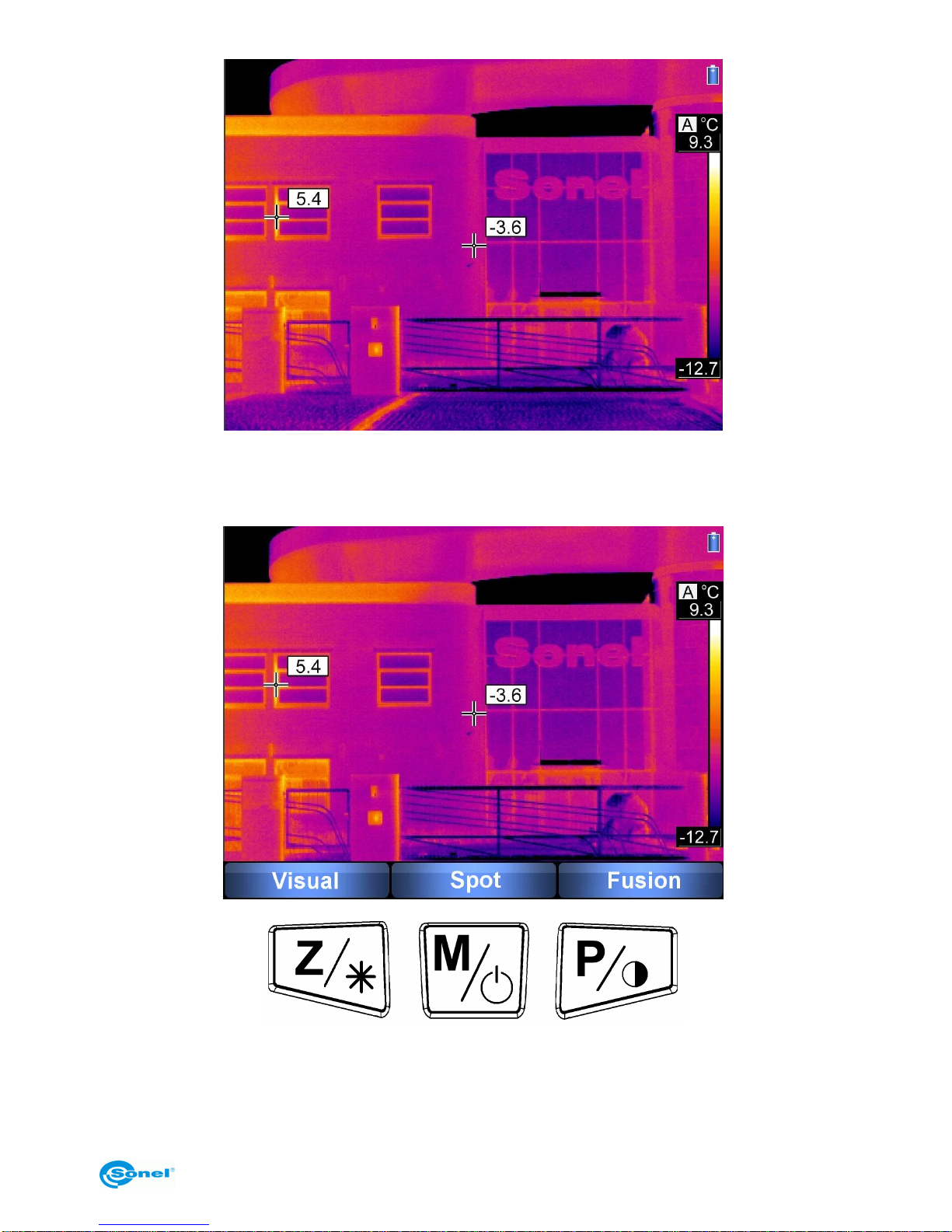
2.2 Display
During operation of the camera, the infrared image is shown on the screen (1) in real time
(the image is refreshed 50/60 times per second). In the right part of the screen, there is a
temperature range bar with corresponding colours for displaying. The value of tempera-
ture at the central point of the screen is always displayed as well as either the highest or
the lowest temperature of the marked point in the observed area, depending on the se-
lected temperature alarm mode (min. or max. - see section 3.11.2):
OPERATING MANUAL
9
After activating any function or performing a measurement, in the bottom part of the
screen a menu appears, where each of the available functions is executed with one of the
corresponding buttons:
In the above example, the left button marked as Z corresponds to the "Visual" command,
the central button marked as M corresponds to the "Spot" command, and the right button
marked as P corresponds to the "Fusion" command.

SONEL KT-384 THERMAL IMAGER
10
2.3 Arrangement of information on the screen

OPERATING MANUAL
11
3 Operating and adjusting the camera
3.1 Turning the camera on/off
In order to turn the camera on, press and hold the button for longer than 3 seconds.
A welcome logo will be displayed, followed by the results of self-test of the instrument, and
after the completion of testing, the camera is ready to be used and enters the mode of in-
frared image display in real time.
To turn the camera off, press and hold the button until the display turns off.
3.2 Focus adjustment
After directing the camera towards the examined object, turn the lens (9) to set the best
focus of image.
3.3 Zooming in (x2, x4)
When no menu is displayed on the screen, pressing the button will cause switching
to the zoom mode - the image on the screen will be digitally magnified two times. Pressing
the button again will switch the image to the x4 zoom mode. In these modes, focus can be
adjusted precisely - but no other functions are accessible. The "zoom" modes are sig-
nalled by or in the top left corner. Pressing the button
restores normal image mode.
3.4 Temperature range
When no menu is displayed on the screen, press and hold the button for 2 s.

SONEL KT-384 THERMAL IMAGER
12
Pressing the button selects automatic adjustment of displayed temperature range -
the minimal and maximal temperatures will be automatically adjusted by the instrument
while the measurement is performed, depending on the range of temperatures detected in
the observed area.
Pressing the button causes entering manual adjustment of temperature range. Se-
lecting this mode causes entering a menu of setting the upper limit of the temperature
Tmax:
By pressing the button or , the upper limit of the displayed temperature range
is increased/decreased (the changed value is additionally marked by a red frame). Press-

OPERATING MANUAL
13
ing the button causes switching over to setting the lower limit of the temperature
range, which can, just like the upper limit, be adjusted with the buttons and :
Pressing the button causes switching over to setting the upper limit of the tempera-
ture range.
The manually selected temperature range is confirmed by pressing the trigger switch (10).
Information about the choice of the automatic or manual range will be displayed after-
wards for 2 seconds in the top left corner of the screen. Additionally, current mode is indi-
cated as "A" (auto mode) or "M" (manual mode) displayed over the upper temperature
limit value.
3.5 Image modes
When no menu is displayed on the screen, press the button briefly. A screen is dis-
played allowing for selecting one of the 3 image modes:
1. After selecting the "Visual" mode (button ) the camera will display only visible im-
age (additional information is shown in the top part of the screen). By pressing the trigger
switch (10), operation in infrared mode is resumed.
2. The "Spot" function allows for changing the position of the spot (by default located in
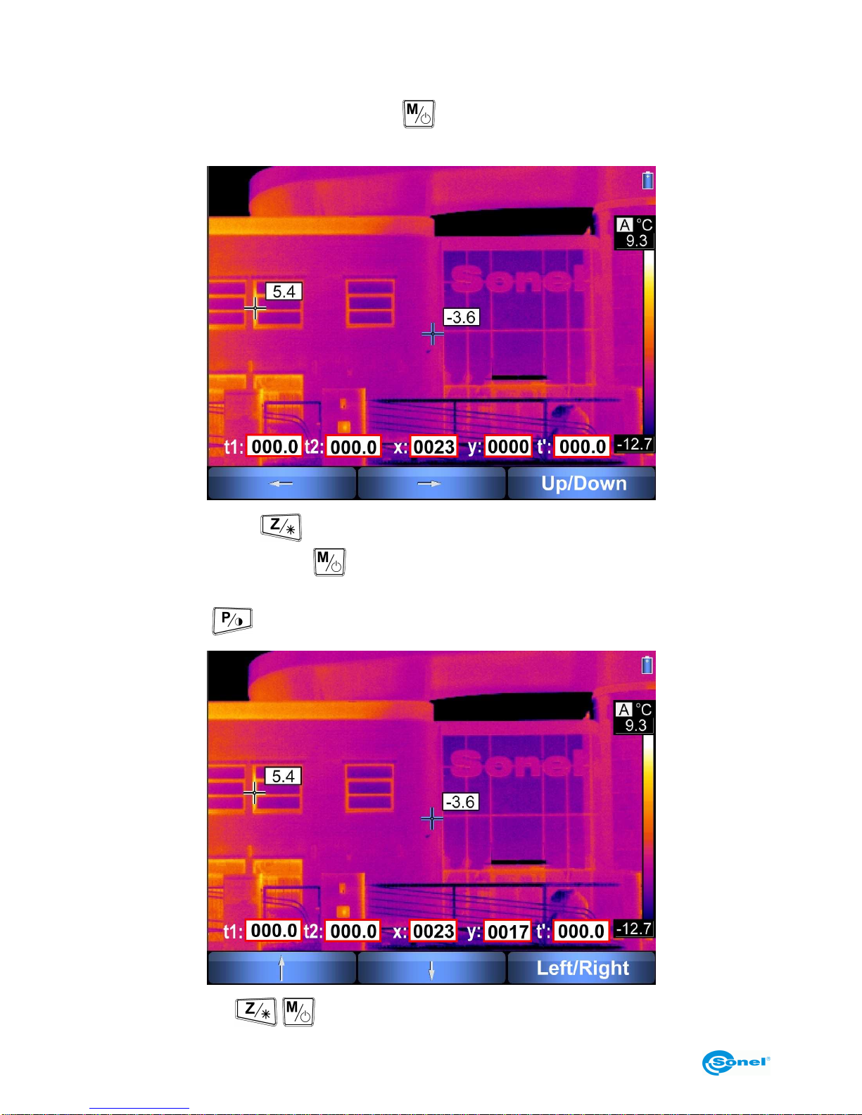
SONEL KT-384 THERMAL IMAGER
14
the centre of the screen), for which the temperature value is always measured and shown,
and show the exact difference between results of two succesive measurements. After se-
lecting this function (pressing the button ), the screen assumes the following appear-
ance:
Pressing the button
causes moving the temperature readout spot to the left,
whereas pressing the button causes moving the spot to the right (new coordinates in
reference to the centre of the screen are displayed, and the spot is marked with blue
lines); pressing causes switching over to the "Up/Down" mode:
where the buttons / change the vertical location of the readout spot, and press-
OPERATING MANUAL
15
ing the button causes switching over to the "Left/Right" mode. Regardless of the
readout spot position, a pointer indicating maximal or minimal temperature is also con-
tinuously displayed on the screen.
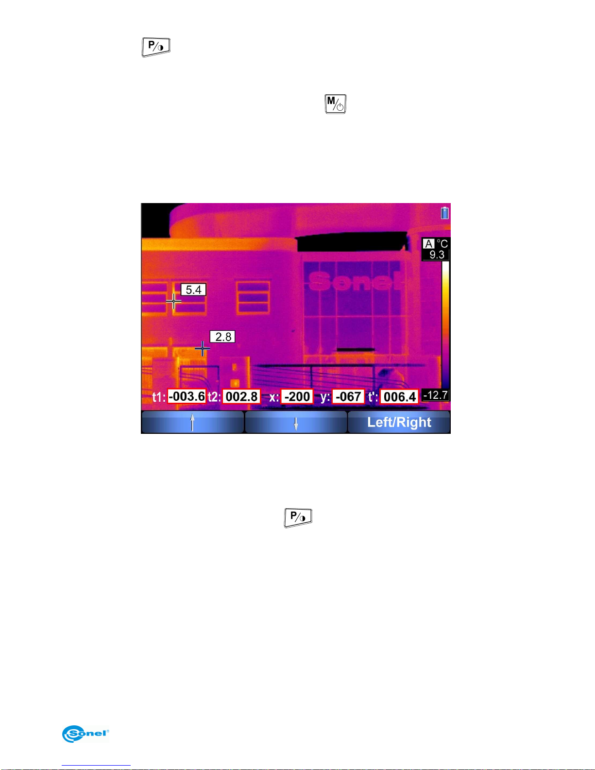
In the ”Spot” mode after pressing simultaneously and trigger switch (10), the meas-
ured temperature (of the readout spot – center or moved; the coordinates are shown in
fields x and y) will be saved in field t1. If the location of the readout spot is changed, as
described above, or the camera is moved to other object, the next simultaneous press of
[] and trigger switch (10) will save the current temperature to field t2. The difference be-
tween t1 and t2 is displayed in field t’.
Pressing the trigger switch (10) causes leaving the "Spot" mode and the return of the
temperature readout spot to the centre of the screen.
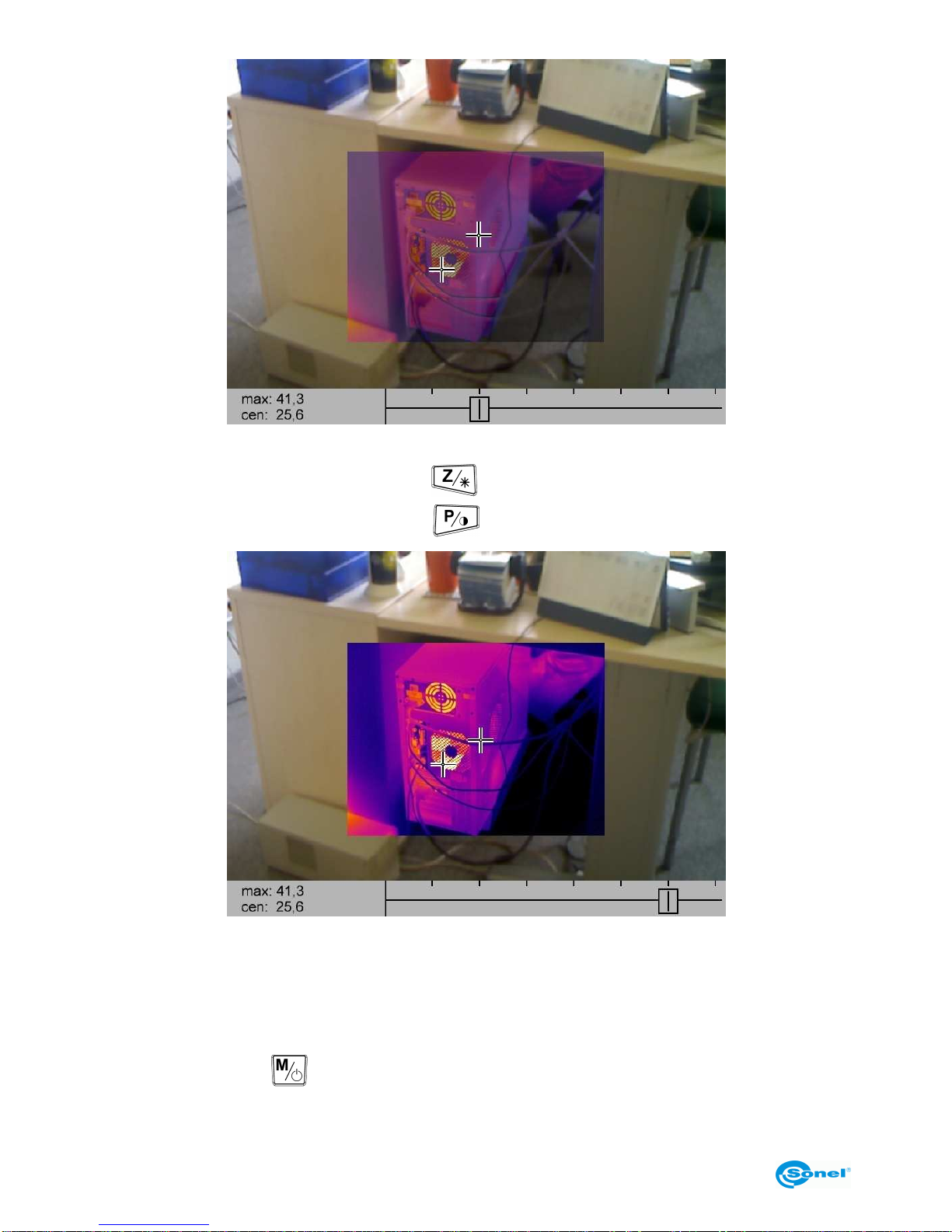
3. "Fusion" mode.
After selecting the "Fusion" mode (button ), the screen will display centrally located
thermal image fused with visible image:
SONEL KT-384 THERMAL IMAGER
16
In the bottom part of the screen, a slider is displayed showing the value of image fusing
ratio - by sliding it to the left (button ) the thermal image intensity is decreased,
whereas by sliding it to the right (button ) the intensity is increased:
The place of maximal temperature (or minimal - depending on the chosen temperature
alarm mode - see section 3.11.2) is continuously marked as well as the central spot of the
examined area; the values of their respective temperatures are given in the bottom left
corner: "max" - maximal temperature (or "min" - minimal) as well as "cen" - central spot
temperature.
Pressing the button causes switching over to a special mode of fused images, where
these images are displayed in full. Part of the image, with temperatures within the range

OPERATING MANUAL
17
shown on the bottom bar, is displayed as thermal image, and the remaining part of the
image, with temperatures out of this range, is displayed as a visible image.
Adjustment of the temperature range limits is performed with buttons: pressing
causes increasing the temperature, decreasing it; toggles between adjusting
the minimal and maximal values of the range.
The temperature range can be selected freely between 0 and 400°C
Pressing the trigger switch (10) causes switching over to the infrared image mode.
NOTE:
- Using FUSION modes is recommended for distances longer than 1.5 m; in case of
shorter distances, the images are shifted vertically (parallax phenomenon).

SONEL KT-384 THERMAL IMAGER
18
3.6 Manual calibration
During operation, the camera runs periodic auto-calibration (it is signalled with the symbol
appearing in the top left corner). Calibration can also be run manually at any time.
When no menu is displayed on the screen, press simultaneously (briefly) the button
and the trigger switch (10). Then calibration will be run and signalled just like the auto-
matic one.
3.7 Laser pointer
The laser pointer can be turned on (when there is no menu invoked on the screen) after
pressing and holding the button (turning on occurs after approx. 1.5 sec.), and is
turned off after releasing the button or after pressing the trigger switch.
NOTE!
In case of direct contact, the laser beam can damage eyesight, therefore
DO NOT DIRECT EYESIGHT TOWARDS THE LASER BEAM,
or direct the beam towards persons or animals!
Take particular care, because the laser beam can reflect off shiny surfaces.
When the laser pointer is turned on, an additional message is displayed on the screen -
.
Due to safety reasons, the function is accessible, if the laser was previously activated in
the menu parameters settings (see section 3.11.6 - "Function settings").
3.8 LED flashlight
In order to facilitate operation of the instrument in dark spaces, the camera is equipped
with a LED flashlight. This function is invoked by simultaneous pressing the buttons
and
.
A function bar is displayed in the bottom part of the screen, where pressing "+"
(button ) causes turning the flashlight on and increasing its brightness (3 levels),
pressing "" (button ) causes decreasing its brightness until it is turned off; pressing
"OK" confirms flashlight brightness (or turning it off) and causes leaving this function. The
flashlight will be on with the set brightness until the function is invoked again or the cam-
era is turned off.

OPERATING MANUAL
19
Information of turned on flashlight is displayed symbolically in the top right corner of the
screen; shape of the symbol changes depending on the brightness level:
min.
max.
3.9 Dew point
The dew point value is displayed after simultaneous pressing of buttons and .
The information is calculated based on room temperature and humidity.
The dew point is an indication of moisture content in the air and defines the value of tem-
perature at which the cooled down air becomes saturated with water vapour - thus it is the
temperature (in °C) at which water vapour turns to water under current working pressure.
When air temperature reaches dew point, condensation of water occurs on ground sur-
face and objects as dew, hoarfrost, rime; also on walls of rooms, etc.
3.10 Capturing and saving image with a voice annotation
The camera displays image in continuous manner, refreshing it 50/60 times per second.
In order to capture the image at a given moment, press the trigger switch (10) - this will
freeze the image and display a screen menu:

SONEL KT-384 THERMAL IMAGER
20
- Pressing "Save" (button )
causes saving the captured image (without a voice note)
and switching over back to the real time display mode.
- Pressing "Visual" (button ) switches the screen to visible image mode (a still visible
image corresponding to the captured thermal image is displayed), pressing the button
again or the trigger switch (10) switches the screen back to the captured thermal
image.
- Pressing "Voice" (button ) causes switching to a voice annotation recording mode
(max. 1 minute):
Selecting "Record" (button ) starts recording of a voice annotation. During recording,
the current length (in seconds) of the recording is displayed over the command bar.
The user can interrupt the process at any time by pressing the trigger switch (10); this
causes returning to the "Save - Voice - Visual" menu without recording any voice annota-
tion.
Other manuals for KT-384
1
Table of contents
Other Sonel Laboratory Equipment manuals


