IGP-2500
TheDCoutputonthisgeneratorhasaratedvoltageof12Vwitharated
currentof8.3A.
DC Applications
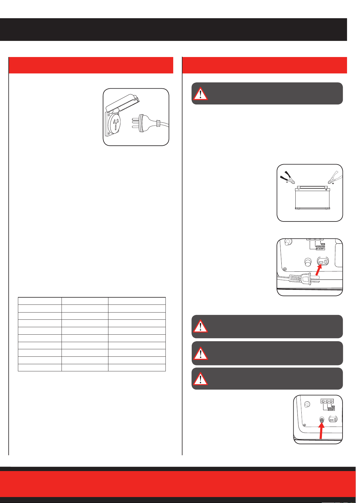
12Volt DC Outlet
Thisissuitableforchargingmostleadacidtypecarbatteries.
Beforecharging,removethebatteryfromthevehicle.Thebattery
MUSTbetotallyisolatedfromanyothercircuitry.
1. Connectthepositive(+,RED)
charging cord to the positive
battery terminal. Connect the
negative(-,BLACK)chargingcord
to the negative battery terminal. Do
notreversethechargingcables,or
serious damage to the generator
and/or the battery may occur.
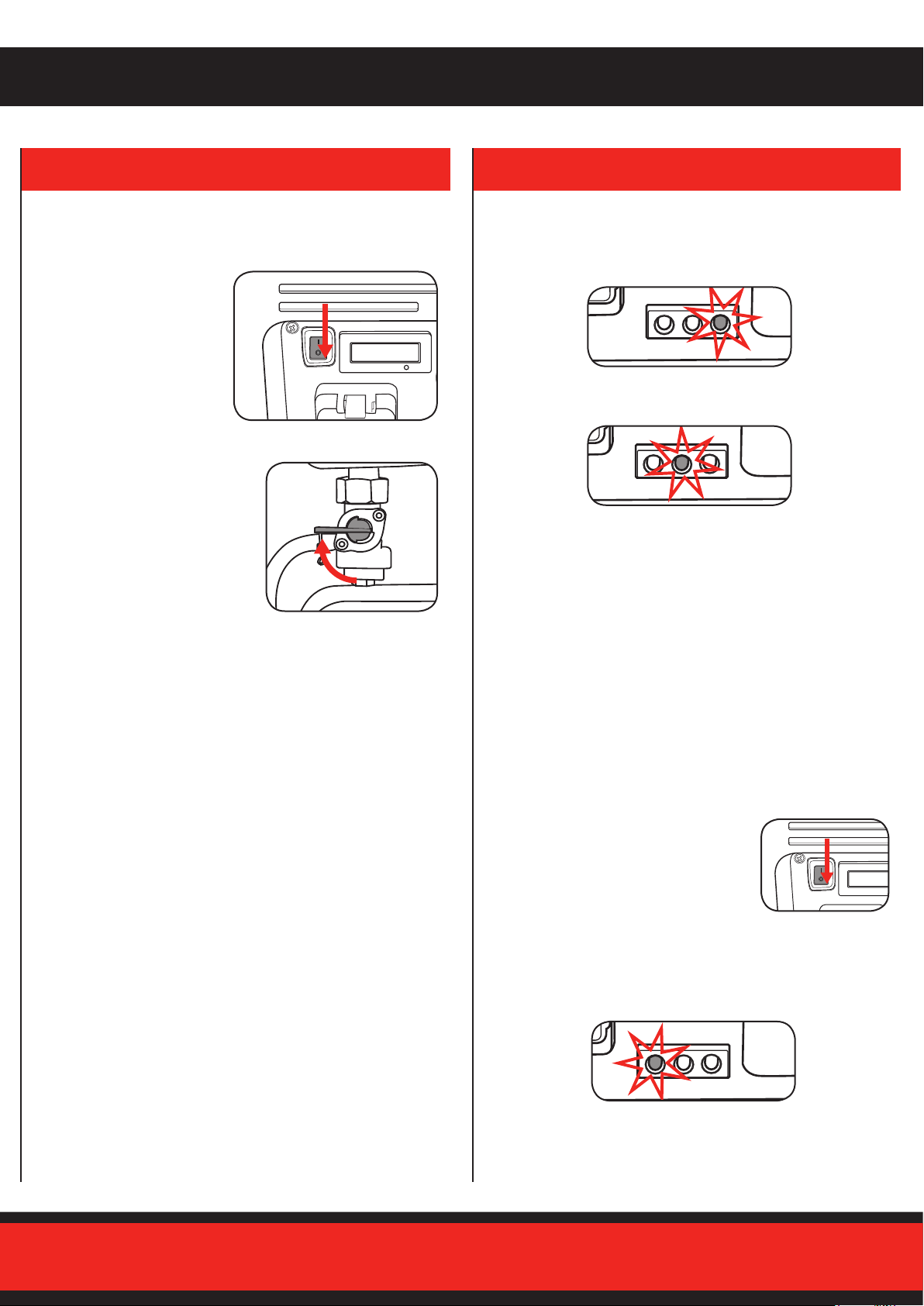
ON
I
0
IGP 2500
AC 240V
DISPLAY METER
RATED POWER 2.2kW
MAX. POWER 2.5kW
OFF
DC PROTECTOR +DC 2V 3.3A-
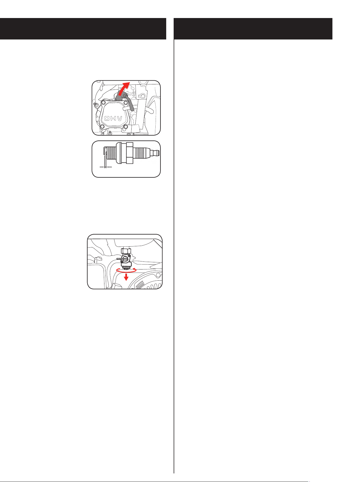
2. Start the generator as described in “Starting the engine” section.
3. Connect the DC cable to the 12Volt
DC outlet. The battery will begin
charging.
4. Whendisconnecting,removethe
plugfromthegeneratorbefore
unclipping the clamps on the
battery.
Note: Donotattempttochargelithiumion,NiCadorNiMHbatteries.
ThechargingoutletisonlyintendedforLeadAcidbatteries.
WARNING! THE BATTERY GIVES OFF EXPLOSIVE
GASES; KEEP SPARKS, FLAMES AND CIGARETTES
AWAY. PROVIDE ADEQUATE VENTILATION WHEN
CHARGING.
WARNING! THE BATTERY CONTAINS SULPHURIC
ACID (ELECTROLYTE). CONTACT WITH SKIN OR EYES
MAY CAUSE SEVERE BURNS. WEAR PROTECTIVE
EQUIPMENT.
WARNING! BATTERIES LEFT UNATTENDED CAN
POTENTIALLY EXPLODE, RESULTING IN SERIOUS
INJURY.
WARNING! THIS GENERATOR IS NOT SUITABLE FOR
PERMANENT HOUSEHOLD INSTALLATION AND/OR
APPLICATIONS.
ON
I
0
IGP 2500
AC 240V
DISPLAY METER
RATED POWER 2.2kW
MAX. POWER 2.5kW
OFF
DC PROTECTOR +DC 2V 3.3A-
Note: DC receptacle can be used while the
ACpowerisinuse.Ifyouusebothatthe
sametime,besurenottoexceedthetotal
powerforACandDC.AnoverloadedDC
circuitwilltriptheDCcircuitbreaker.Ifthis
happens,disconnecttheDCloadbefore
pushinginthe‘DCOverloadReset’buttonto
resume operation.
Whenreconnectingappliances,reducetheloadwhichpreviously
overloaded the generator.
AC Applications
Checkthetotalratingoftheappliance
to be connected and ensure the rating
oftheappliance/sdoesnotexceedthe
ratingofthegenerator.
1. Start the engine and make sure
theoutputindicatorLED(green)
illuminates.(see“Starting the
engine”)
2. ConrmthattheequipmenttobeusedandtheACpowerswitch
onthecontrolpanelisswitchedo,andinserttheplugofthe
equipment to be used into an AC socket.
3. Switch the AC power switch on the control panel up into the on
position and then you can start using the equipment.
Note: Iftheconnectedappliancedoesnotoperate,referto“Overload
Indicator” section.
Note: Pleasebeawarethatthestartingcurrentofcertainequipment
may be higher than it is rated.
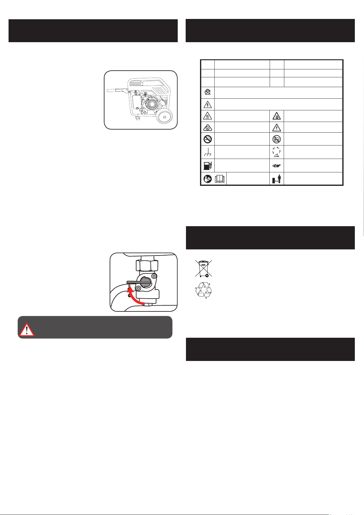
Appliance Running Wattage Start-up Wattage
Light 70W 70W
Airless Sprayer 650W 1300W
Refrigerator 700W 2000W
Water Pump 800W 2000W
AirCompressor(1HP) 1100W 4000W
Circular Saw 1200W 2100W
Heater 2000W 2000W
Mitre Saw 2100W 3200W
Electric Stove 2400W 2400W
Overloading (Inrush Current)
Youmayndthateventhoughtheapplianceyouwishtoconnecttothegenerator
isbelowtheratedpower,thegeneratoroverloads.
Someappliancesrequireahigherpowerthannotedontheapplianceforstartup;
this is called inrush current. Some examples are listed below.
*Tabledetailsareapproximate.Alwayscheckyourappliancefortheaccuratewattage.