Welding
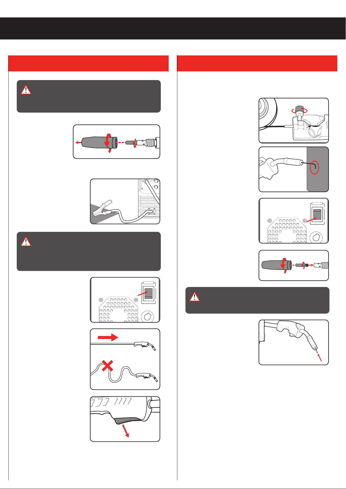
1. Ensure that the workpiece is clamped down securely, is cleaned
and prepared for welding.
2. Attach the earth clamp to the
workpiece ensuring there is
good metal to metal contact.
Note: Prior to connecting
the earth clamp it may be
necessary to clean the surface of the work piece using the metal
brush. Clamp it where it will not be in the way. This clamp provides
an earth connection back to the welder.
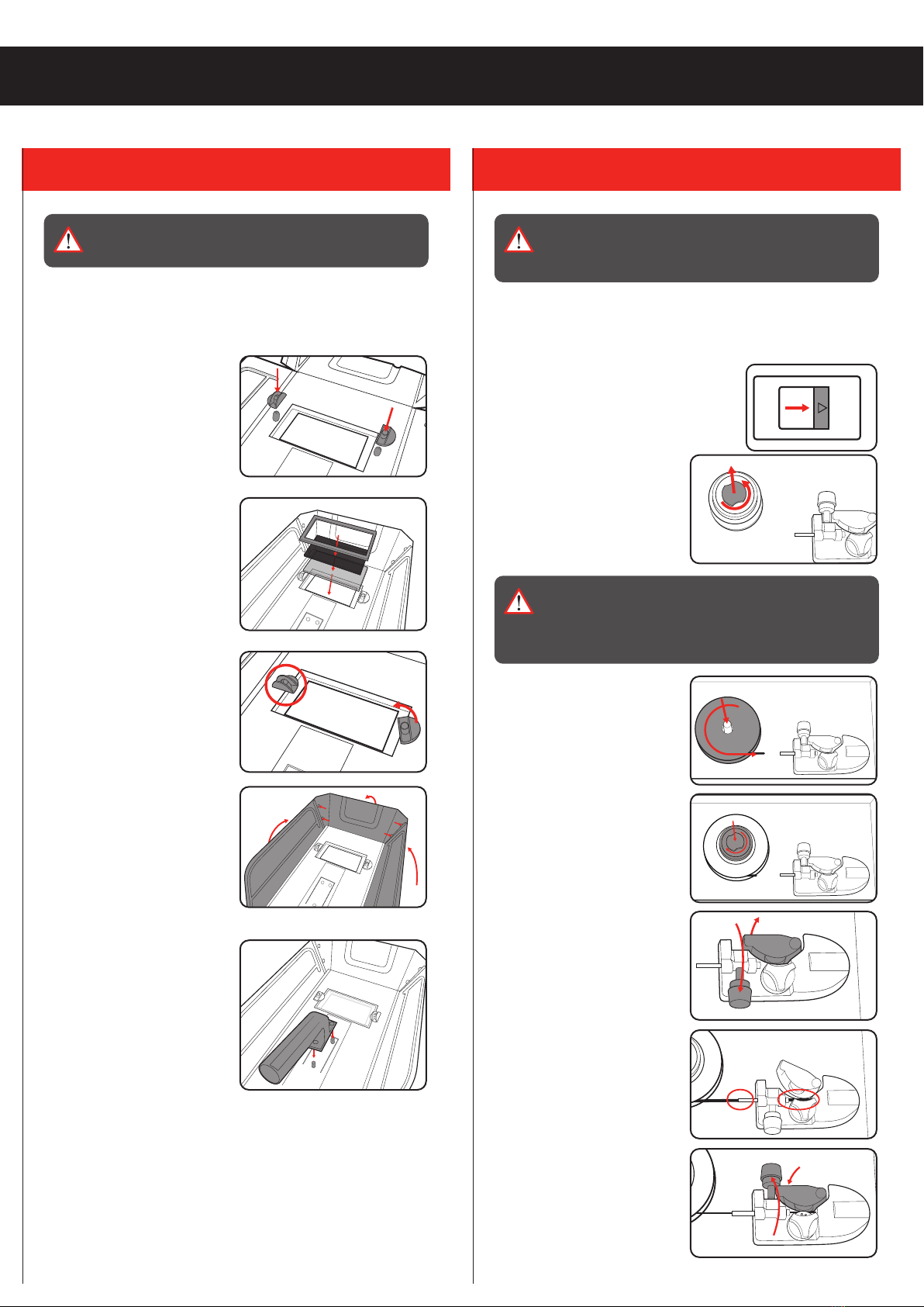
3. Switch the welder on and position the
welding mask in front of your eyes.
4. Position the wire tip approximately 8mm
from the workpiece at a 20° angle from the
vertical in the direction of movement.
Note: Leaving a 10mm length of protruding
wire and holding the torch so that the wire
touches the workpiece is a good way to
estimate the proper placement.
5. Squeeze the torch trigger to start the
weld.
6. WELDING5. INDICATOR LEDS
0
I
AC 240V ~ 50Hz
OFF
ON
AC POWER
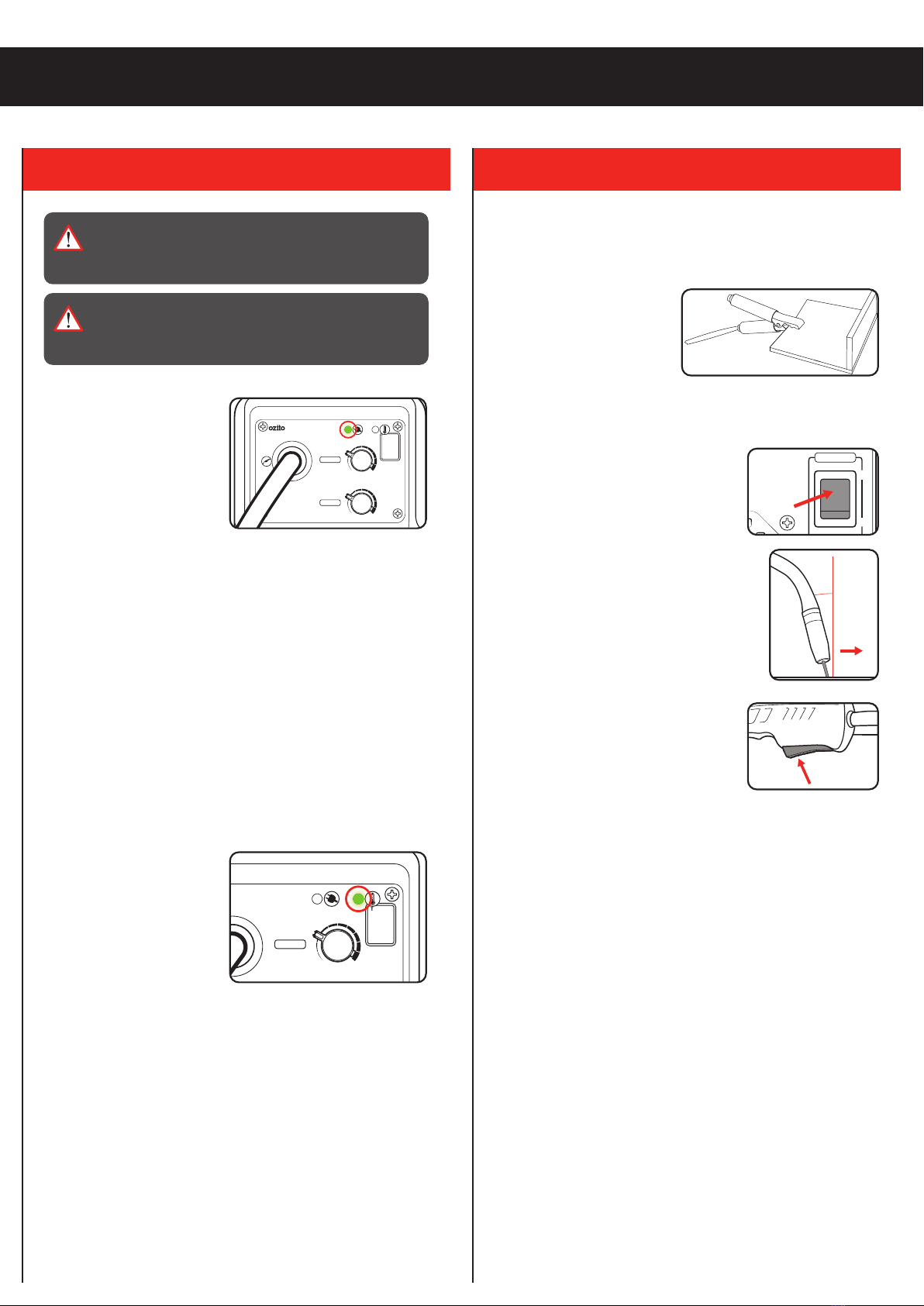
Power LED Light
1. The ON LED illuminates
when the power cord is
connected to a live mains
outlet and the on/off switch
is in the on position.
Note: The cooling fan will
operate when the unit is
switched on.
Thermal Overload Protection
All Welders have a feature called a duty cycle. Duty cycle on a
welder refers to the time in which the welder operates during
normal welding. A welder can only weld for a certain continuous
period of time before it requires to cool down.
If the internal components of the welder should become hot
the welder could overheat. If the welder overheats the Thermal
Overload Protection feature will automatically shut down the
welder.
THIS CAN OCCUR IN HEAVY USE AND DOES NOT INDICATE A
FAULT.
The Welder will cease to weld
and the Thermal Overload
LED light will turn on. This
LED indication light is just to
inform you that your welder is
becoming too hot and requires
a cool down to protect the
internal components of the
welder.
Do Not turn your welder Off as the welder has an internal cooling
fan and this will assist your welder to cool down quicker. Reducing
the cooling time will enable you to get back to your welding job
quicker.
Depending on how many Amps or how heavy the welding you are
doing the cooling time may take up to 10 minutes for your welder
cool down so you can return to your welding job.
Duty cycle % as referenced on the rating label are based on 10
minute intervals. For instance with a 20% duty cycle, one can weld
continuously for 2 minutes, but then must wait 8 minutes for the
welder to cool.
Lower current levels have longer duty cycles.
ON
THERMAL
OVERLOAD
ALLOW
WELDER
TO COOL
DOWN
!
100A INVERTER
MIG WELDER
VOLTAGE
MIN MAX
FEED RATE
MIN MAX
ON
THERMAL
OVERLOAD
ALLOW
WELDER
TO COOL
DOWN
!
100A INVERTER
MIG WELDER
VOLTAGE
MIN MAX
FEED RATE
MIN MAX
WARNING! IF THE WELDER OVERHEATS & THE
THERMAL OVERLOAD PROTECTION ENGAGES,
DO NOT TURN OFF THE WELDER AS THE FAN WILL
ASSIST IN SPEEDING UP THE COOLING TIME.
WARNING! ENSURE THE CLAMP & THE TORCH IS
AWAY FROM THE WELDING MATERIAL & PLACED
ON A NON-CONDUCTIVE SURFACE WHILE THE
OVERLOAD PROTECTION IS ENGAGED.