9
O3 GENERATOR COOLING WATER IN: is the 1/4
inch brass female NPT fitting on the side of the control-
ler near the cooling water flow meter. This must be
connected to a consistent water supply of cool fresh
water.
O3 GENERATOR COOLING WATER OUT: is the
1/4 inch brass female NPT fitting on the side of the
controller near the cooling water flow meter. This is the
drain from the ozone generator cooling loop. This water
should be plumbed safely to a drain.
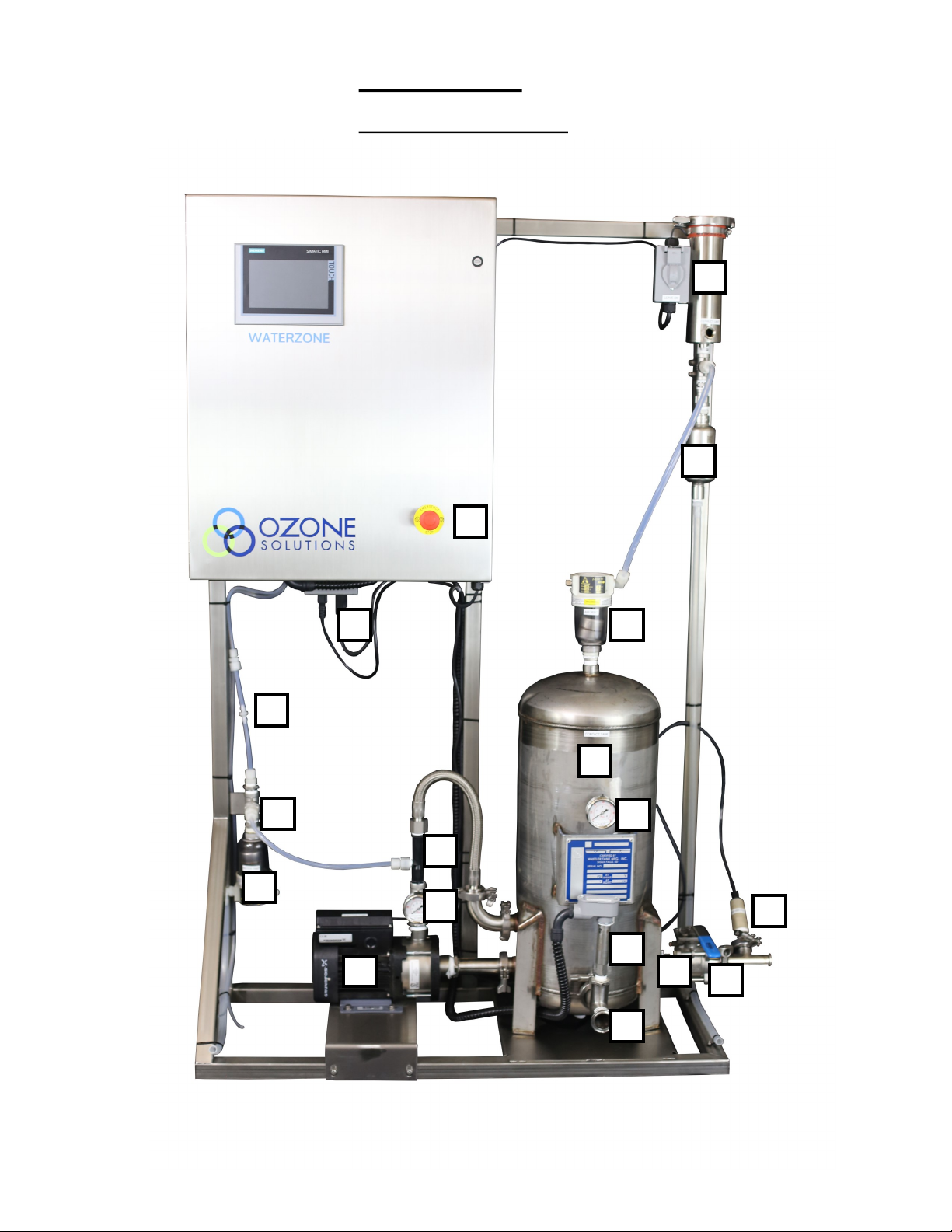
Water Sample Port
Ozone residual in the water must be checked periodi-
cally to ensure proper operation of the Ozone Injection
System. This is also used to calibrate the dissolved
ozone sensor (if applicable). After the output of the
Ozone Injection System, a small tee with a ball valve
should be placed in the water line. This will allow for
samples of water to be pulled to verify the dissolved
ozone level in the water.
Dissolved Ozone Monitor
The dissolved ozone probe is shipped installed. This
probe is shipped with a protective cap on the end to
keep it protected from damage, and keep it moist. This
probe will be damaged if it becomes dry.
Read and understand the instructions provided for the
sensor before installing it into the line. Install it only
after all other plumbing for the Waterzone is complet-
ed, and the system is ready to be filled with water.
ORP Sensor
The ORP probe is shipped installed. This probe is
shipped with a protective cap on the end to keep it pro-
tected from damage, and keep it moist. This probe will
be damaged if it becomes dry.
Read and understand the instructions provided for the
sensor before installing it into the line. Install it only
after all other plumbing for the Waterzone is complet-
ed, and the system is ready to be filled with water.
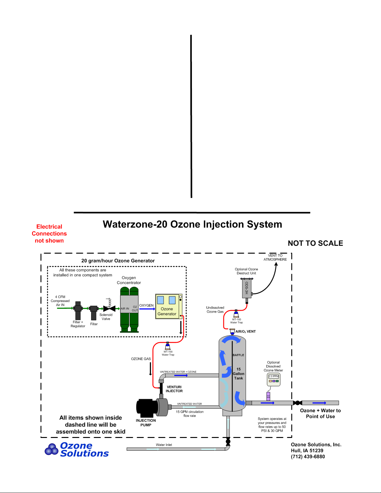
Air Vent
The air vent is located on the top of the Contact Tank.
The 1/2 inch port exiting the air vent will need to be
plumbed outdoors away from human contact or to a
suitable ozone destruct unit, as it will be off-gassing
small amounts of high-concentration ozone. Ozone-
compatible tubing and fittings should be used for this
purpose.
Some Waterzone systems are configured with an
Ozone Destruct Unit installed on the skid. If pre-
sent, the gas exiting this ozone destruct unit
should still be plumbed to a safe location in the
event the destruct unit fails for any reason. It is
important that this gas is removed from human
contact and vented to a safe location.
Water Trap Drain
The Water Trap is located on the Ozone Injection
Skid. This water trap will drain any water that
may be pushed from the Venturi Injector toward
the Ozone Generator; this is a protection device
for the Ozone Generator. There may also be a wa-
ter trap installed to drain any water from the off-
gas vent outlet prior to the ozone destruct unit.
These water traps may collect a small amount of
water that will need to be plumbed away to a
drain. Any drain tubing must be run DOWNHILL
in order to freely drain. Use tubing with an ID of
no less than 3/8 inch, with a maximum if 5 feet.
Electrical Power Connections
The system requires a 120 Volt, 3-wire, 20 Amp,
50/60 Hz single phase circuit. The unit is installed
with a NEMA cord end for easy power up.
Optional Electrical Connections
CAUTION: Voltage may be present at connection
terminals! Disconnect all power before servicing.
Terminals are provided for connection of external
contacts to control and monitor the system. The
terminals are located inside the System Controller.
Drill holes in the System Controller as necessary
for connection of external control wiring.
These connections may be used optionally as de-
sired. Some terminals are jumpered from the fac-
tory to allow the system to operate without exter-
nal connections. On terminals which are jump-
ered, the jumper must be removed upon connec-
tion of remote contacts.
If control wires are used in the terminals currently,
these can be run in series with any remote control
device of your choice to power the system
remotely.