-5- AIO-OZONE Installation & Programming Guide
Power Supply Jack
Power Supply Jack
for Control Valve
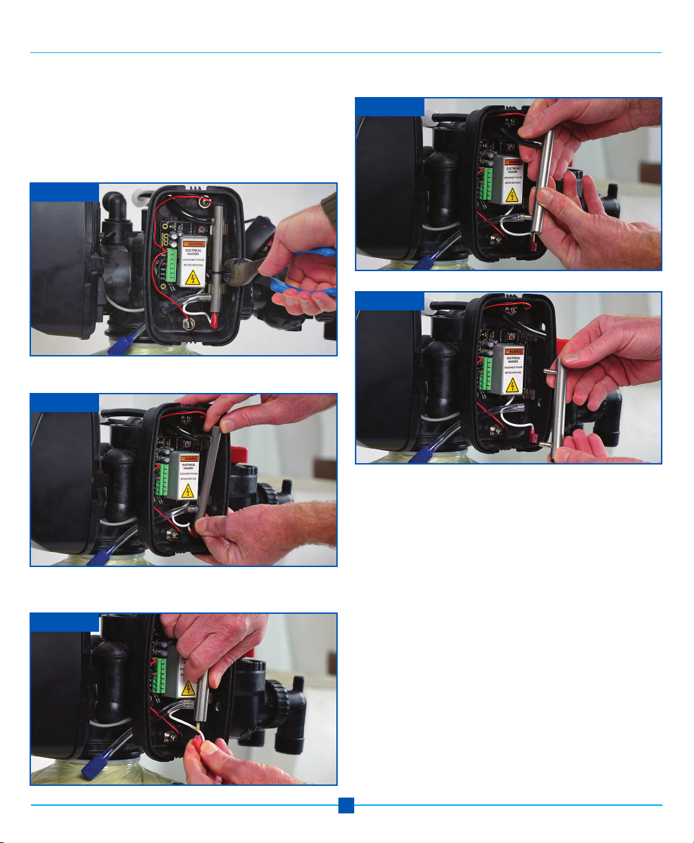
Installation of EOG Unit continued
EOG Unit Indicator Light- Photo 1
Green Light Blinking Slowly - Standby mode
Green Light Blinking Quickly - High voltage startup
Green Light Solid - High voltage is ON & stable; CD cell
producing ozone
Red Light Solid - Unstable high voltage; CD cell may
need cleaned
Green/Red Light Alternating Twice/Second - HV is ON,
but current is low
Red Light Flashing - NO or NC contacts are shorted
Orange Light - 1 year timer has expired; clean CD cell,
then push reset button to reset timer Photo 2.
Note: Holding reset for 3 seconds will change pulsing
green LED to solid green if the cell is in good operating
order. If LED changes to solid red, the cell needs cleaned.
Photo 2
Photo 1
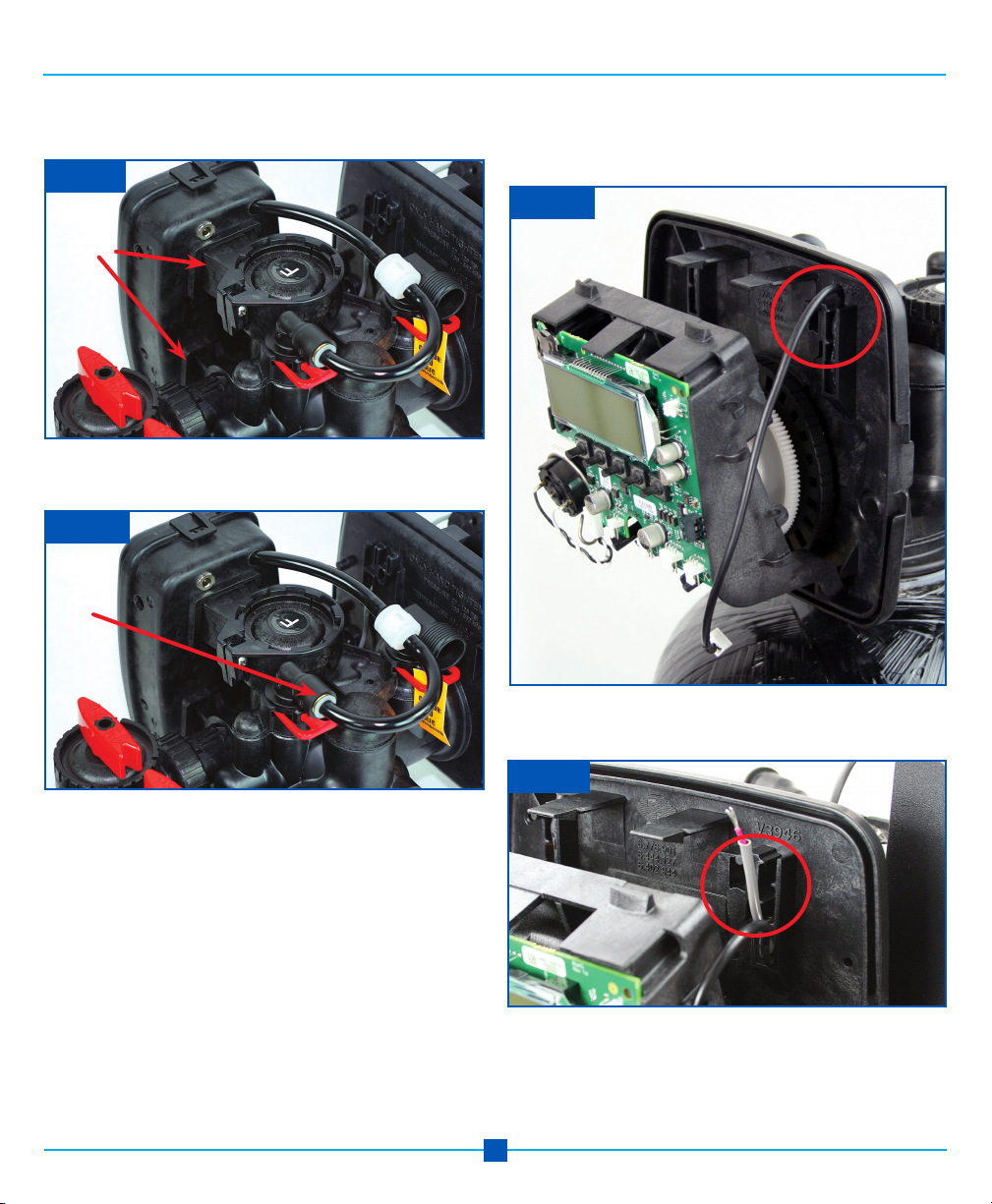
Step 17: For Nelsen Unit using the integrated power sup-
ply cord connect the control valve power supply cord to
the power supply jack. Plug in the EOG to the wall outlet.
Once you power either system, the pulsing green LED
may turn to pulsing orange. Pressing the reset button will
reset it to pulsing green.
Nelsen EOG Model
At this point installation of your Enhanced Oxidation Gen-
erator is complete. Continue to page 8 for programming
instructions.
Flashing Green/Red means that the circuit is looking for
an optimum frequency to operate within. It is still making
ozone in the mode and will eventually go to solid green
or red.