OZTI OTI 4478 User manual

ozti
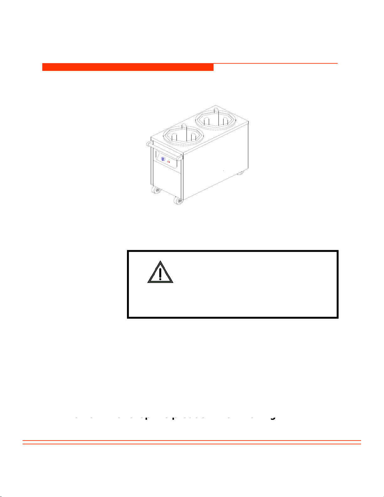
DISH DISPENSER (ELECTRICAL)
USER’S MANUAL
PRODUCTION YEAR: SERIAL NO
PRODUCTION SITE : Beylikdüzü Eski Hadımköy Yolu 1.Km Büyükçekmece İstanbul/TÜRKİYE
Phone : 0090 212 886 78 00 (8 Hat
Lines) Fax : 0090 212 886 66 29
MANUFACTURER :ÖZTİRYAKİLER MADENİEŞYA SAN. VE TİC A.Ş.
Phone
:
0090
212
886
78
00
(8
Hat
-
Lines)
Fax
:
0090
212
886
66
29
PUBLISHED ON : 23.01.2004 VER . 04 Page1 of 14

TABLE OF CONTENTS
PAGE NR
TOPICS
PAGE
NR
.
TOPICS
1 COVER PAGE
2 TABLE OF CONTENTS
3 INTRODUCTION
4 TECHNICAL DATA
5 ELECTRICAL CIRCUIT DIAGRAM
6 MAIN DIMENSIONS AND CONTROL BOARDS
7
WARNING SIGNS
7
WARNING
SIGNS
8 SAFETY DETAILS
9 TRANSPORTING AND MOVING
10
INSTALLATION OF THE
APPLIANCE
10
INSTALLATION
OF
THE
APPLIANCE
11-12 OPERATION OF THE APPLIANCE
13 CLEAN-UP AND MAINTENANCE
14 TERMS OF WARRANTY
CAUTION
This applıance should only be used in facilities where relevant standards,
laws and safety requirements are complied with
2/14

INTRODUCTION
Dear User,
Thank you for purchasing our appliance and for your reliance upon our
company. Our appliances are used in professional kitchens in 75 countries.
Our appliances are produced in compliance with international standards
Our
appliances
are
produced
in
compliance
with
international
standards
.
Important notice: Please read and ensure that the users read this user’s
manual in order to achieve the desired performance in line with your
expectations and to use your appliance for long years. Please take the
warnings mentioned above into consideration before calling for service...
☞Please read and ensure that your operation personnel also reads this user’s
l f ll b f i t lli d i th li If th li i
manua
l
care
f
u
ll
y
b
e
f
ore
i
ns
t
a
lli
ng an
d
us
i
ng
th
e app
li
ance.
If
th
e app
li
ance
i
s
operated without reading the user’s manual, the appliance will not be covered
by the warranty.
☞The manual containing information about installation, usage and maintenance
of our product you purchased should be read carefully. Please ensure that
power supply connections to the appliance are already installed by qualified
personnel according to local legislation, before our authorized service
personnel arrives for the installation of the appliance.
☞If you are confused or you don’t have enough information
please get in touch with authorized service by phone
please
get
in
touch
with
authorized
service
by
phone
.
☞Please keep in mind that, if the service personnel is delayed
at your site, related expenses and delay costs will be charged to
you on hourly basis.
W h th t ill t th b t f f d t
☞
W
e
h
ope
th
a
t
you w
ill
ge
t
th
e
b
es
t
per
f
ormance
f
rom our pro
d
uc
t
…
3/14

TECHNICAL DATA
YOUR
PRODUCT'S
TYPE OTI 4478 OTDN 1050 OTI 4444 OTDN 4444 OTI 43 OTKN 43
MAIN
DIMENSIONS
(mm) 440X780X850 440X780X850 440X440X850 440X440X850 430X850 430X850
TOTAL
ELECTRICAL
INPUT (kW) 3 - 1,5 - 1,5 -
POWER
SUPPLY
VOLTAGE (V) 220 - 240 - 220 - 240 - 220 - 240 -
WORKING
FREQUENCY
(Hz) 50 - 50 - 50 -
THERMOSTA
THERMOSTA
T RANGE
(°C) 30-90 -30-90 -30-90 -
SUPPLY
CABLE
(H07 RNF) 3 X 1,5 - 3 X 1,5 - 3 X 1,5 -
DISH
CAPACITY
100
100
50
50
50
50
CAPACITY
(Pieces)
100
100
50
50
50
50
MAXIMUM
SLOPE 5° - 5° - 5° -
CLASS 1 - 1 - 1 -
PROTECTIO
N CLASS IP 20 - IP 20 - IP 20 -
4/14

ELECTRICAL CIRCUIT DIAGRAM
H2
N
PE L2
LS1 T1
L2
L1 H1
N
PE
LS1
L1 H1 L1
T1 LT2
LT1
OTI 4444 OTI 4478
N
PE L1 H1
CODE
COMPONENTS
OTI 43
CODE
COMPONENTS
H1, H2 Resistance
S1 Switch
L2 Thermostat lamp
L1 Thermostat
T1, T2 Power lamp
5/14

MAIN DIMENSIONS
50
0
1000
0
500
500
8
50
850
8
OTI 4478
CONTROL BOARDS
OTI 4444
C
D
CDD
A
B
B
C
A
B
A
OTI 4478
OTI 4444 OTI 43
A : ON-OFF SWITCH
B : THERMOSTAT
C : POWER LAMP
D : THERMOSTAT SIGNAL LAMP
6/14

WARNING SIGNS
PE
POWER NETWORK GROUNDING GROUNDING
OVERHEATPOWER
POWER SUPPLY CONNECTIONS
220-240 V NPE / 50 Hz
VOLTAGE: 220-240 V
SUPPLY CONNECTION: SINGLE PHASE
GROUNDED
GROUNDED
FREQUENCY : 50 Hz
7/14

SAFETY DETAILS
☞Any kind of flammable solid and liquid material (cloths,
alcohol and derivatives, petrochemical products, wooden
and plastic materials, cutting blocks, curtains etc.) should
never be held near the applıance.
☞You can use this applıance simultaneously together
with other products of ours.
☞Do not clean up the applıance with pressure water
☞This applıance should be installed in line with effective
regulations and only be operated in well ventilated
places. Please refer to the instructions before installing
and operating the applıance.
☞This applıance is designed for industrial use and
should only be operated by personnel trained on the
applıance.
☞The applıance should not be handled by
unauthorized persons except for the manufacturer or
authorized service.
☞In case of fire or flame in the area where the applıance
is operated, act without panic, close gas valves, turn off the
power switches and use a fire extinguisher. Never use water
to extinguish the fire.
8/14
TRANSPORTING AND MOVING
For devices installed by an
authorized service, POWER
SUPPLY CABLES CANNOT BE
EXTENDED OR REPLACED except by an
authorized service.
☞Before moving the applıance disconnect power supply.
☞The applıance may be moved with manpower.
☞
Do not hit or drop the
product
when moving.
9/14
Do
not
hit
or
drop
the
product
when
moving.

INSTALLATION OF THE APPLIANCE
If this applıance located near to any wall, separation, kitchen
furniture, decorative coating etc. the distance in between
should be min.20 cm. and if those are coated with fireproof heat insulating
material, the distance should be min.5 cm. It is strongly recommended that fire
safety protection instructions are observed.
safety
protection
instructions
are
observed.
All of the items mentioned below in connection with the
installation of the applıance should be carried out by
authorized service personnel
☞Power supply connection of the applıance should be checked by
an eligible electrician, and it should be connected to a fuse at a
maximum hei
g
ht of 170 cm.
authorized
service
personnel
.
g
☞Power supply connection should be made using a 30 mA current
leakage fuse as a protection against current leakage danger.
☞Power installation to be used should be grounded by connecting
it to a grounding bar at the nearest panel.
10/14
This manual suits for next models
5
Table of contents
Popular Dispenser manuals by other brands

Silver King
Silver King Majestic SK12MAJ Technical manual and replacement parts list

Franke
Franke F3Dn Twin Service manual

STIEBEL ELTRON
STIEBEL ELTRON UltraHot Plus Operation and installation instructions

DAN DRYER
DAN DRYER 282 installation guide

Essity
Essity Tork 473208 manual

CBS
CBS SD300BU-88 COMPONENT MAINTENANCE MANUAL WITH ILLUSTRATED PARTS LIST


