P.A. SRF-48 User manual


Form 1189 SRF-48 ROLL FEED 4/1/2009
2
TABLE OF CONTENTS
DESCRIPTION PAGE
1. INSTALLATION.........................................................................................................................................................3
1.1. MECHANICAL INSTALLATION.....................................................................................................................3
1.2. ELECTRICAL INSTALLATION ......................................................................................................................4
1.3. LOADING THE FEED......................................................................................................................................5
1.4. THREADING THE TOOL................................................................................................................................7
1.5. RUNNING THE FEED.....................................................................................................................................8
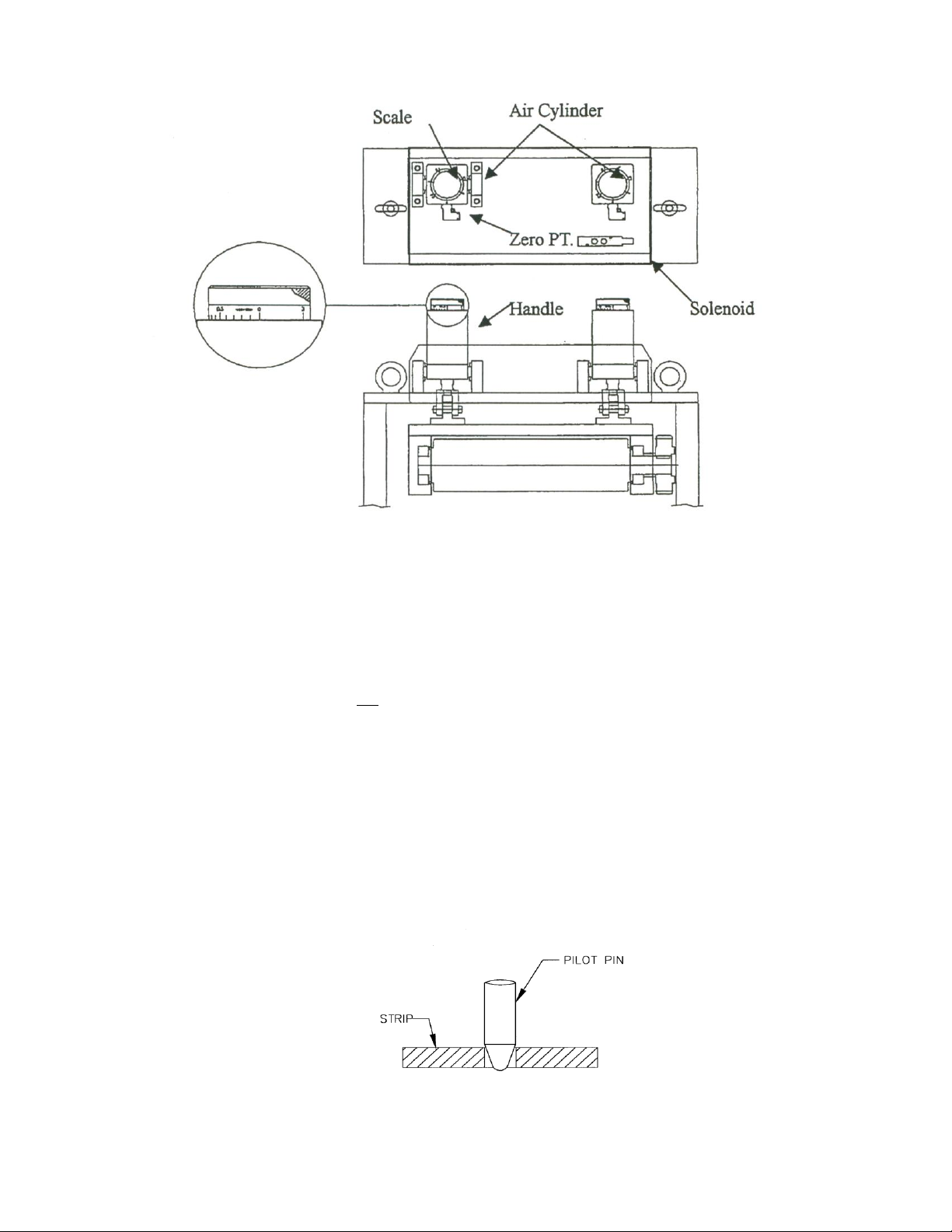
1.6. PNEUMATIC PILOT RELEASE.....................................................................................................................9
2. MAINTENANCE......................................................................................................................................................10
3. MECHANICAL PARTS...........................................................................................................................................11
3.1. PARTS LIST....................................................................................................................................................15
4. WARNING................................................................................................................................................................17
5. SAFETY PROGRAM..............................................................................................................................................17
6. WARRANTY............................................................................................................................................................17

Form 1189 SRF-48 ROLL FEED 4/1/2009
3
1. INSTALLATION
1.1. MECHANICAL INSTALLATION
The SRF-48 Roll Feed is supplied with an adjustable mounting bracket. The feed should be securely mounted to the
press frame. (A transition bracket is sometimes required in certain applications.) The feed should be centered, square,
and perpendicular to the pass line of the press. It should be mounted at a height that will accommodate the appropriate
die sets.
The feeder may be used to push or pull strip stock through the die.
The electro-pneumatic piloting will need another cam switch for controlling feed roll opening and closing.

Form 1189 SRF-48 ROLL FEED 4/1/2009
4
1.2. ELECTRICAL INSTALLATION
The Ultra Control has been designed to make electrical connections quickly and easily. All that is required is a "clean"
source that must be connected to the main disconnect switch.
The inputs and outputs to your press control (i.e. Emergency Stop, Feed Cam Signal, Pilot Release Cam Signal, Reset
Cam Signal) must also be connected for proper operation.
Note, that if your feed is supplied with P/A PLS (Programmable Limit Switch) you don’t have to wire Feed and Reset
Cam signals.
The motor connects to the electrical control by factory installed "Amphenol" (Military Specifications) Quick connectors.
The optional PLS connects to the electrical controls by factory installed Military Quick connector.
IMPORTANT!
A GROUNDING CONDUCTOR MUST BE INSTALLED FOR PROPER MACHINE GROUNDING.
NOTE:
All connections should be made in accordance with National Electrical Code (NEC) requirements and must
comply with all local ordinances.
NOTE:
A word about electrical “noise” - Most pressroom environments contain considerable electrical noise. It is
emitted from electro-mechanical press relays, contacts, and solenoids. While the Ultra Control is designed to
minimize “self generated” electrical noise, it is difficult to provide protection for all applications. If erratic
system behavior is experienced, then the source of the "noise" must be suppressed with either a
resistive/capacitive type of suppressor on AC coils, or “Avalanche” type diodes on DC coils.
NOTE:
The Ultra Control is fully protected by line circuit breakers.
NOTE:
The electrical control enclosure is supplied with a stand/support, which may be placed in any convenient location.
The enclosure may also be mounted in any fixed location as long as the cabling is adequate to reach the feed. It is
not recommended that the electrical enclosure be mounted directly to the press. The vibrations caused by the
punch press can result in damage to the control system

Form 1189 SRF-48 ROLL FEED 4/1/2009
5
1.3. LOADING THE FEED
FIGURE 3
Prior to this step, the electrical control must be powered up and all needed parameters are loaded.
(Refer to the Ultra Operating Manual.)
NOTE:
This example is based on using PLS (Programmable Limit Switch), but all PLS timing notes can be easily
translated to other forms of timing.
1. Put the Ultra control into “MANUAL MODE”. Record the present settings of the Feed Cam, Reset Cam, and
Pilot Release Cam into a job set-up record sheet for future reference to the job.
Table of contents