P.LEMMENS CB2 TAC4 REC User manual

KLIMAATTECHNIEK
Als het om lucht gaat.
T 0320 - 28 61 81 | www.auerhaan-klimaattechniek.nl

2

9
CB2 TAC4 REC
Installatie handleiding
(v.08/2014)
1) Principeschema
Opstelling van de T° sondes
Air (1) = Verse lucht (buiten →binnen) Air (2) = Binnenlucht (binnen →buiten)
In de REC kasten zijn er 3 bevestigingshaken voorzien om de sondes te monteren.
2) Aansluitschema's
Zie de specifieke aansluitschema's per werkingsmode in bijlage.
Het starten/stoppen van de ventilator dient te gebeuren via de ingangen K1/K2/K3 (softstop) en niet door
de 230V voeding te onderbreken.
3) Werkingsmodes
De controlebox CB2 TAC4 REC kan in 3 modes geconfigureerd worden:
MODE CA :
De installateur definieert 3 constante debieten (m³u K1, m³u K2 et m³u K3).
Deze worden geactiveerd via de ingangen K1/K2/K3
MODE LS :
De debietwaarde staat in functie van een 0-10V signaal dat op ingang K2 is aangesloten (lineaire relatie).
De relatie LS wordt vastgelegd door 4 ingegeven waarden Vmin, Vmax, m³u≡Vmin en m³u≡Vmax.
Principeschema :
EXTRACTIE
ventilator
pulsieventilator

10
De waarde m³u≡Vmin kan hoger of lager zijn dan m³u≡Vmax.
In de geavanceerde setup is het mogelijk om de ventilatoren te
stoppen indien het ingangssignaal lager of hoger ligt dan de
ingegeven limieten.
MODE CPs :
Het luchtdebiet wordt automatisch aangepast om zo een door een sonde gemeten drukwaarde constant te
houden.
4) Antivriesbeveiliging
Om ijsvorming op de recuperator te voorkomen is er achter de recuperator aan de extractiezijde een sonde
(T3) gemonteerd die mee de werking van de pulsieventilator (ventilator 1) bepaald.
-Bij door T3 gemeten temperaturen hoger dan +5°C: de instructie uit de SETUP wordt niet beïnvloed.
-Bij door T3 gemeten temperaturen tussen +5°C en 1°C: de instructie uit de SETUP wordt als volgt
aangepast :
•In CA en LS, het pulsiedebiet varieert tussen 100% en 33% (AF
low
) van het
instructiedebiet (AF
n
)
•In CPs, de druk varieert tussen 100% en 50% (AF
low
) van de instructiedruk (AF
n
)
Het LED AF zal oplichten.
-Bij door T3 gemeten temperaturen lager dan 1°C wordt de pulsieventilator gestopt totdat de
gemeten temperatuur terug hoger is dan +2°C gedurende 5 minuten. Het LED AF zal knipperen.
Deze temperatuurwaarden kunnen in de Advanced setup worden veranderd. (zie www.lemmens.com)
Principschema
LED AF aan
LED AF knippert

11
5) Bedienen van de by-pass
In functievan de binnen- enbuitentemperatuur zal hetCB2 TAC4REC destand van de by-passklep regelen.
Vergeet niet om de optie servomotor te kiezen bij het selecteren van uw luchtbehandelingskast (wordt niet
standaard gemonteerd)
De bypass zal opengaan (*) indien aan ALLE van de volgende voorwaarden is voldaan :
-Buitentemperatuur (sonde T1) is lager dan de binnentemperatuur (sonde T2) – 1°C.
-Buitentemperatuur (sonde T1) is hoger 15°C.
-Binnentemperatuur (sonde T2) is hoger 22°C.
De bypass sluit indien aan de EEN volgende voorwaarden is voldaan :
-Buitentemperatuur (sonde T1) is hoger dan de binnentemperatuur (sonde T2).
-Buitentemperatuur (sonde T1) is lager dan 14°C.
-Binnentemperatuur (sonde T2) is lager dan 20°C.
Deze waarden kunnen in de Advanced Setup veranderd worden (zie www.lemmens.com)
(*)Als de by-pass geopend is, dan is het drukalarm inactief.
LED BYPASS OFF
By-pass gesloten
R1
LED BYPASS ON
By-pass open
R1
6) Configuratie
Het instellen van het controlecircuit doet u via het LCD-scherm en met de 4 toetsen SETUP,
↑
,
↓
en ENTER.
Om de configuratie te starten drukt u op SETUP totdat SETUP op het scherm verschijnt.
Principe: gegevens inbrengen doet u telkens met de ↑↓knoppen en met de ENTER knop om te bevestigen.
Getallen worden cijfer per cijfer gevormd.
Hieronder vindt u de eenvoudigde configuratie in geval van gebruik van één ventilator.
Voor een compleet technisch overzicht kan u op onze website terecht, www.lemmens.com
1 LANGUAGE Keuze van de taal
2 VENT TYP Keuze type ventilator (CID – zie etiket op de ventilator).
3 MODE Keuze van de werkingsmode (CA, LS, CPs)
Als MODE CA
4 m³u K1? Per ingang K1/K2/K3 kan u een debiet instellen. Kies eerst het debiet voor ingang K1
(contact tussen klemmen K1 en +12V gesloten).
5 m³u K2? Kies het debiet voor ingang K2 (contact tussen klemmen K2 en +12V gesloten)
6 m³u K3? Kies het debiet voor ingang K3 (contact tussen klemmen K3 en +12V gesloten)
Als MODE LS
4 V min? Keuze van de minimumspanning voor de LS relatie
5 V max? Keuze van de maximumspanning voor de LS relatie
6 m³/u≡Vmin Keuze van het debiet dat moet overeenkomen met Vmin
7 m³/u≡Vmax Keuze van het debiet dat moet overeenkomen met Vmax
8 % op K3? Keuze van de multiplicator voor de LS relatie (op debiet), actief indien het contact tussen
de klemmen +12V en K3 gesloten is.
VERVOLG als MODE CA of LS
9 %AF/TOE Kies het percentage voor het extractiedebiet (ventilatoren F2) in functie van de
pulsiedebieten (ventilatoren F1).
10 CONFIG
KLOK? N Kies J om de klok (uur + datum) te configureren.
11 TIJD
SCHEMA?N Kies JA om de uurschema’s te activeren.
Voor een compleet technisch overzicht kan u op onze website terecht, www.lemmens.com

12
12 DRUK
ALARM? Het drukalarm is facultatief. Indien u dit niet wenst in te stellen kies dan N. In het andere
geval kies J.
13 ∆P TOE Kiest u voor J:
Kies het drukinterval aan de pulsiezijde (met de drukwaarde die bij het initiële debiet hoort
als referentie).
14 ∆P AF Kies het drukinterval aan de extractiezijde (met de drukwaarde die bij het initiële debiet
hoort als referentie).
15 INIT Pa REF? Initiëren van de referentiedruk (niet nodig indien reeds eerder gebeurd).
16 m³u INIT Kiest u voor J: Instellen van het drukalarm:
Geef het debiet in in functie waarvan de referentiedruk moet worden berekend.
17 Pa REF INIT
xxxx m³u
xxxx Pa
Initiëren van de referentiedruk is bezig. Dit kan tot 3 minuten in beslag nemen.
Het weergeven van het debiet en de druk is bezig.
18 ALARM
RESET? Reset van de alarmen (indien gewenst kies J).
19 EINDE SETUP De configuratie van het circuit is nu beëindigd.
Als MODE CPs
4 CPs op
TOEVOER
Keuze tussen constante druk aan de pulsiezijde (kies TOEVOER),aan de extractiezijde
(kies AFVOER) of aan beide (kies TOEV+AFV).
Kiest u voor TOEV+AFV ga dan verder naar stap nummer 7
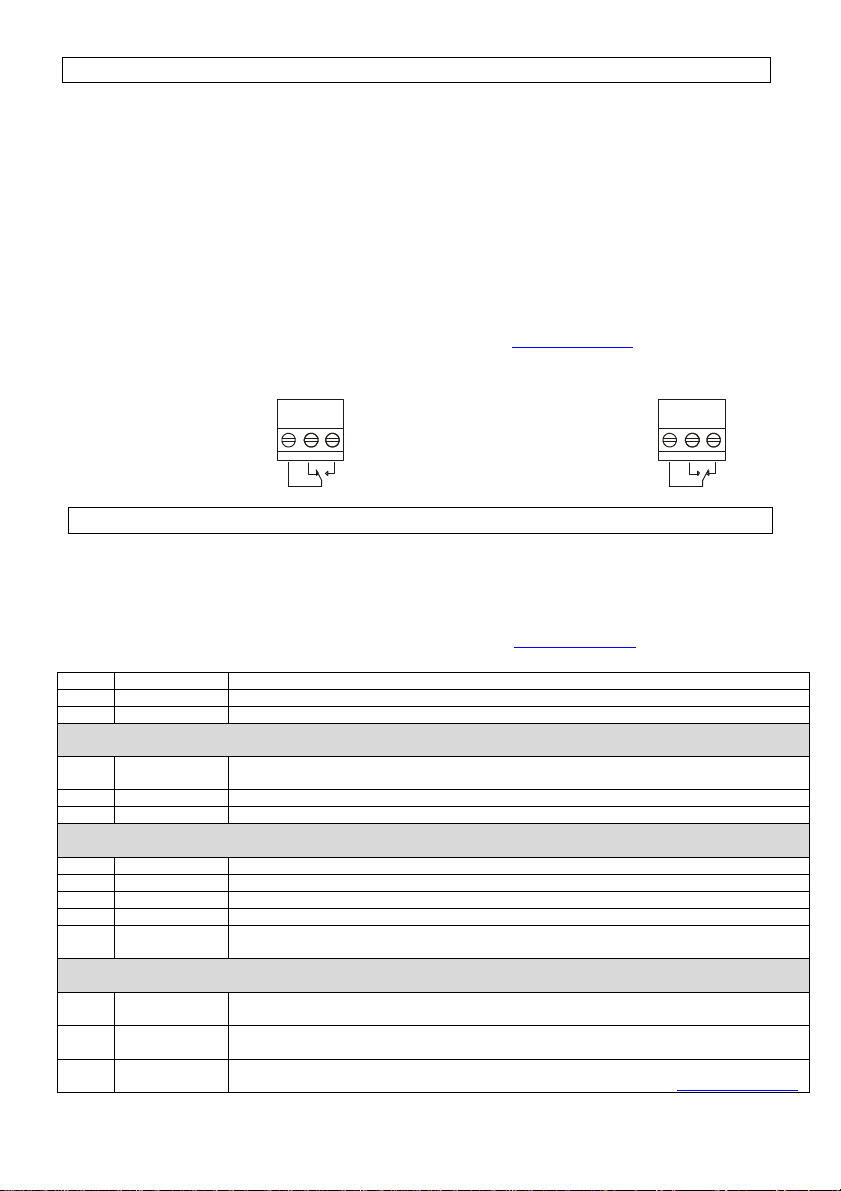
5 % op K3? Multiplicatorkeuze van de CPs instructie:
Actief indien het contact tussen de klemmen +12V en K3 gesloten is.
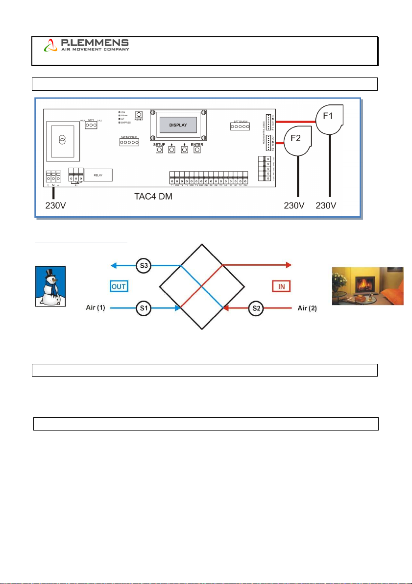
6 %AF/TOE Keuze van de verhouding tussen het extractiedebiet (ventilator F2) en het pulsiedebiet
(ventilator F1)
7 CONFIG
KLOK? N Kies J om de klok (uur + datum) te configureren.
8 TIJD
SCHEMA?N Kies JA om de uurschema’s te activeren.
Voor een compleet technisch overzicht kan u op onze website terecht, www.lemmens.com
9 INIT CPs REF?
Initiëren van de CPs drukinstructie?
10 INIT via
DEBIET? Mogelijkheid om een constante referentiedrukwaarde in te stellen
- ofwel automatisch op basis van het debiet
- ofwel manueel door de gewenste drukwaarde in te geven
In geval van INIT via DEBIET : de TAC4 DM bepaalt automatisch de drukwaarde
11 INIT TOE
0000m3u Kies het initiële pulsiedebiet dat bij de CPs referentiedruk hoort (indien TOEVOER of
TOEV+AFV gekozen werden in stap nummer 4).
12 INIT AF
0000m3u Kies het initiële extractiedebietg dat bij de CPs referentiedruk hoort (indien AFVOER of
TOEV+AFV gekozen warden in stap nummer 4).
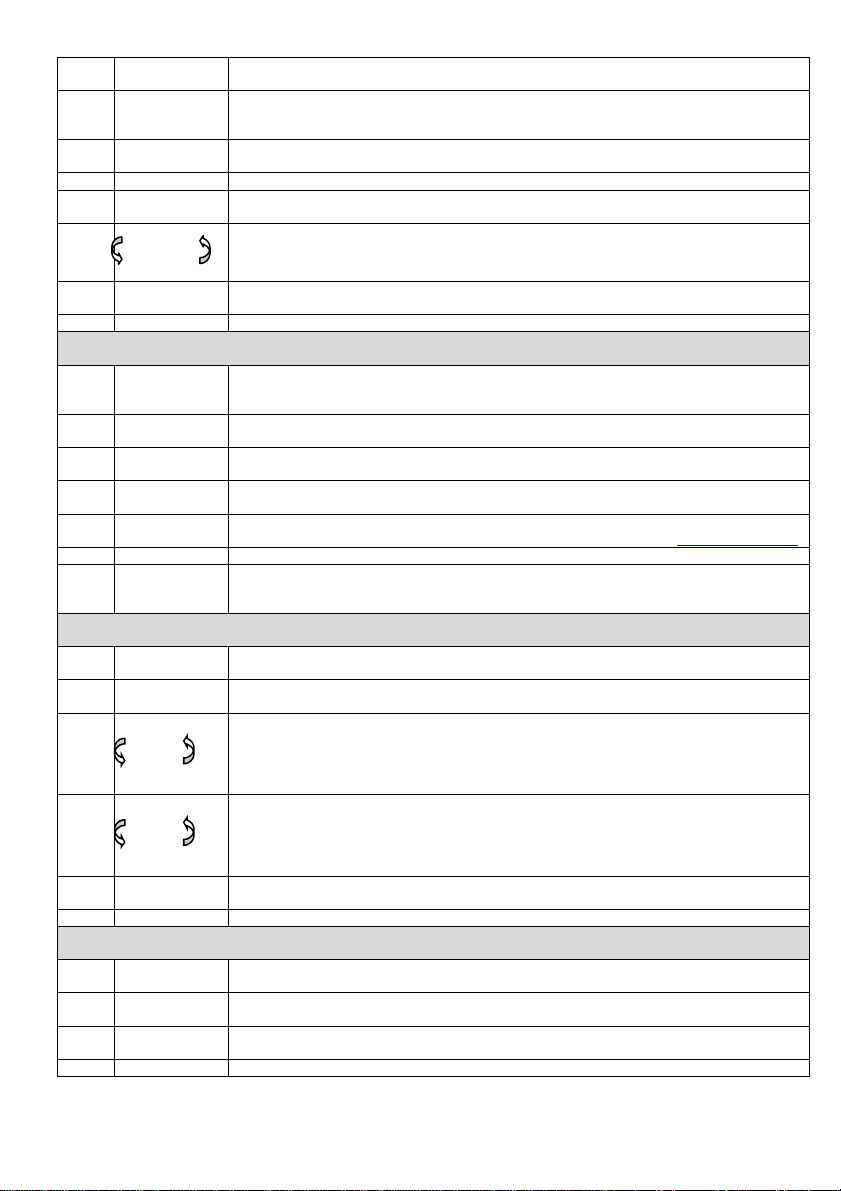
13
INIT TOE
xx,x V
INIT TOE
xxxx m³u
Initiëren van de referentiewaarde is bezig (indien TOEVOER of TOEV+AFV gekozen
werden in stap nummer 4).
Na ongeveer 1 minuut zal het controlecircuit de gemeten drukwaarde die bij het opgegeven
debiet hoort opslaan.
Het pulsiedebiet en van de waarde van de drukvoeler worden berekend.
14
INIT AF
xx,x V
INIT AF
xxxx m³u
Initiëren van de referentiewaarde is bezig (indien AFVOER of TOEV+AFV gekozen werden
in stap nummer 4).
Na ongeveer 1 minuut zal het controlecircuit de gemeten drukwaarde die bij het opgegeven
debiet hoort opslaan.
Het extractiedebiet en van de waarde van de drukvoeler worden berekend.
15 ALARM
RESET? Reset van de alarmen (indien gewenst kies J).
16 EINDE SETUP De configuratie van het circuit is nu beëindigd.
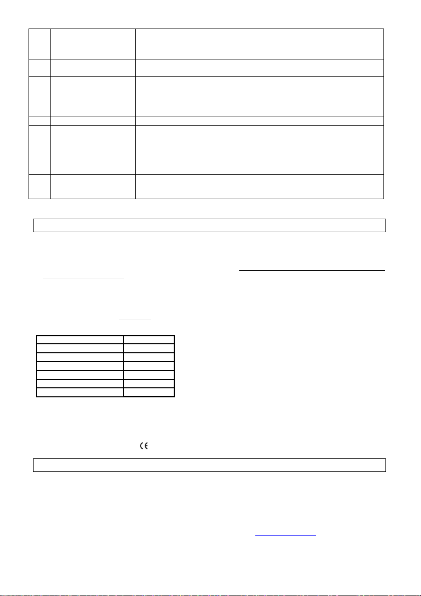
In geval van INIT via DRUK : voer onmiddellijk de regelwaarde in
11 TOE REF?
xx,x V Geef de referentiedrukwaarde voor de pulsiezijde in (indien TOEVOER of TOEV+AFV
gekozen werden in stap nummer 4).
12 AF REF ?
xx,x V Geef de referentiedrukwaarde voor de extractiezijde in (indien AFVOER of TOEV+AFV
gekozen werden in stap nummer 4).
13 ALARM
RESET? Reset van de alarmen (indien gewenst kies J).
14 EINDE SETUP De configuratie van het circuit is nu beëindigd.

13
7) Weergave op het scherm
7.1 Basisweergave
Standaard zullen enkel de debiet, druk, en luchtsnelheidswaarden (volgens geselecteerde setup opties) en de
eventuele alarmen worden weergegeven op het scherm.
Voor een compleet technisch overzicht kan u op onze website terecht, www.lemmens.com
7.2 Weergave van alle parameters
Door op de
↑
en
↓
knoppen te drukken is het mogelijk om alle beschikbare parameters weer te geven.
Voor een compleet technisch overzicht kan u op onze website terecht, www.lemmens.com
8) De werking van de ventilator aangeven
Eén van de 2 relais van de optionele SAT3 geeft aan of de ventilator draait (werkinspunt >20% ingestelde
waarde) of niet.
Via dit relais kan u bijvoorbeeld een electrische batterij onder spanning zetten of een compressor doen starten
enkel indien het contact gesloten is. Dit is een extra veiligheid bij het opstarten omdat u in dit geval zeker bent
dat de ventilator draait. Aansluitschema: Zie bijlage §5.
7) Alarmen
De informatie over het alarm status wordt door de SAT3 module (optie) weergegeven via een potentiaalvrij
contact (O.R.1).
De controlebox CB2 TAC4 REC bevat 12 alarmen:
Geafficheerde tekst Beschrijving
1 ALARM VENTx Dit alarm geeft een ventilatorpanne aan.
Controleer of alle aansluitingen en de netspanning correct zijn aangesloten.
Indien het probleem hiermee niet is opgelost kan het zijn dat de kabel, het
circuit of de motor de oorzaak van het probleem is. (1)
2 DRUK ALARM Signaleert een drukalarm op ventilator.
In dit geval zal het LED alarm oplichten. Het R2 relais van optie SAT3 zal
sluiten en het LED boven het SAT3 relais zal oplichten. (1)
3 Pa INIT ALARM
1) Het reële ventilator debiet < gevraagde debiet: het werkingspunt heeft
een drukniveau dat hoger ligt dan het maximaal toegelaten drukniveau bij
dat debiet.
2)het initiële debiet niet kan worden aangehouden omdat de ondergrens
voor het functioneren van de motor is bereikt. Het debiet van deze ventilator
is dus hoger dan het gevraagde debiet.
3)Druk niet stabiel. (1)
4 ALARM CA, LS of
CPs
Dit alarm geeft aan dat de instructiewaarde niet kan worden bereikt.
Dit betekent dat het gevraagde debiet niet kan aangehouden worden omdat
de over of ondergrens van de motor is bereikt. (1)
Voor dit alarm schakelt het uitgang relay van de SAT3 module niet.
5 DATA ERROR Dit alarm geeft een gegevensfout aan in het controlecircuit. (1)
Om dit type van problemen op te lossen :
- Doe een FABRIEK RESET in de advanced setup (druk gelijktijdig op de
knoppen SETUP en ENTER totdat ADVANCED SETUP verschijnt op het
scherm). Voor verdere uitleg hierover zie specifieke documentatie.
Indien het probleem hiermee niet is opgelost moeten wij het circuit opnieuw
programmeren..
6 BRAND ALARM Dit alarm geeft een brandalarm dat door een extern detectiesysteem wordt
gesignaleerd (via een extern contact).
Na een brandalarm moet u een RESET uitvoeren (via de RESET knop op
het TAC4 DM circuit) om naar de normale werking terug te keren.

14
7 ALARM SERVICE
VEN.STOP SERVICE
Dit alarm geeft aan dat het aantal draaiuren van de ventilatoren de ingestelde
limiet heeft bereikt.
Dit alarm kan de ventilatoren doen stoppen of niet.
8 COM ERROR Dit alarm signaleert een communicatieprobleem tussen de verschillende
modules van de TAC4 DM regeling. (enkel indien optie RC TAC4)
9 ALARM T°
SONDE 1/2/3 Dit alarm signaleert een probleem met 1 van de voelers T1/T2/T3
aangesloten op het TAC4 DM circuit (kortsluiting of niet aangesloten). Deze
voelers zijn nodig voor de antivriesbeveiliging van de recuperator.
Na het oplossen van het probleem moet u een RESET doen via de RESET
knop van het TAC4 DM circuit
10 / /
11 ALARM T°
SONDE 5 Dit alarm geeft aan dat de in het pulsiekanaal geplaatste voeler T5,
aangesloten op het TAC4 DM circuit, defect is (geopend of kortsluiting) of
niet is aangesloten. Deze voeler wordt gebruikt om de pulsietemperatuur
constant te houden na de externe BA/KW.
Na het oplossen van het probleem moet u een RESET doen via de RESET
knop van TAC4 DM circuit
12 ALARM
NAVERW T°
TE LAAG
Dit alarm geeft aan dat de gevraagde pulsietemperatuur niet kan worden
gerespecteerd (te lage temperatuur gedurende 15 minuten terwijl de
naverwarming volledig open staat)
(1) De volledige tekst verschijnt in meerdere opeenvolgende keren op het scherm.
9) Technische gegevens
Voeding: 230VAC (tussen 208V en 240V) - Frequency : 50/60Hz
Aarding: ! VERPLICHT !
Electrische beveiliging:
De motor is intern beveiligd tegen overbelasting.Het is dus niet nodig een electrische beveiliging tegen
overbelasting te monteren. Een eenvoudige beveiliging tegen kortsluiting is voldoende en deze moet rekening
houden met :
- piekstroom van 150 A gedurende 2 à 4 milliseconden bij het starten (indien met schakelaar : een
uitschakelcaracteristiek van het type D selecteren - kortsluitvermogen 10.000A - AC3). Het is verplicht de
softstop functie te gebruiken om deze piekstroom te vermijden;
- wij raden een beveiliging classe AM aan.
Kaliber van de beveiliging/motor
Type
Calibre
TAC 180W
4A
TAC 230W
4A
TAC 1/3 4A
TAC 1/2
4A
TAC 3/4
8A
TAC 1/1
10A
Isolatieklasse
Thermisch : B
Mechanisch: IP44 - De aansluitingen moeten naar onderen toe op de doos worden geplaatst met M16 of M20
wartels (doorbreek voorzichtig de daarvoor voorziene plaatsen in de doos)
Omgevingstemperatuur: -10°C / +40 tot 55°C
Gelijkvormigheid: goedgekeurd – UL.
10) Extra functionnaliteit
De controler TAC4 DM zorgt voor extra functionnaliteit :
- MODBUS RTU, KNX Communicatie
- Afstandbediening RC of GRC TAC4 (via SAT
MODBUS)
- Ingang voor BOOST functie en brand alarm
- Tijdschema
- naverwarwing/koeling regeling via SAT BA/KW
optie
Voor een compleet technisch overzicht kan u op onze website terecht www.lemmens.com :

15
CB2 TAC4 REC
Installation manual
(v.08/2014)
1) Principle of wiring
Positioning of the temperature sensors
Air (1) = fresh air (outside →inside) Air (2) = inside air (inside →outside)
A fixation bracket is mounted in the unit at the 3 corresponding locations.
2) Wiring diagram
See appendix.
The start/stop of the fan must be activated with entries K1/K2/K3 (softstop) and not via power supply
230V.
3) Working modes
The control box CB2 TAC4 REC allows operating in 3 different modes:
CA MODE:
The user defines 3 constant airflow instructions m³h K1, m³h K2 and m³h K3.
These are activated using entries K1/K2/K3.
LS MODE:
The requested airflow is a function of a 0/10V signal connected to entry K2 (linear link).
The user defines the link by giving 4 values: Vmin, Vmax, m³h≡Vmin and m³h≡Vmax.
EXHAUST FAN
SUPPLY FAN

16
Principle:
Value m³h≡Vmin can be smaller or greater than m³h≡Vmax.
Note: in « advanced setup » it is possible to stop the fan when the
signal is lower or higher than set value.
CPs MODE:
The airflow of the fan is automatically regulated to maintain a pressure sensor’s value constant.
4) Antifreeze of the heat exchanger
In order to avoid the risk of frosting the heat exchanger, the supply airflow (ventilator 1) is linked to the
temperature value of the exhaust airflow measured after the heat exchanger (sensor T3).
-T°(T3) > +5°C : the assigned airflow is as defined by SETUP.
-1°C < T°(T3) < +5°C : the airflow assigned by SETUP is automatically modified as follows :
•If CA or LS working mode : the supply airflow will progressively drop down to 33% (AF
low
)
of the assigned airflow (AF
n
)
•If CPs mode, the assigned pressure will drop to 50% (AF
low
) of the assigned pressure
(AF
n
)
In these conditions LED AF is ON.
-T°(T3) < +1°C : the supply airflow is stopped for as long as T°(T3) < +2°C during 5 minutes. In these
conditions LED AF is blinking.
All these temperature SET values can be modified using ADVANCED SETUP. (see www.lemmens.com)
Antifreeze diagram
LED AF ON
LED AF blinking

17
5) By-pass control
According to inside and outside temperatures, the TAC4 DM control will monitor the opening/closing of the
bypass damper. A servo-motor (SMO) will have to be installed (option).
Operating description:
Opening of by-pass(*) if all following conditions are met:
-Outside T° (sensor T1) < inside T° (sensor T2) – 1°C.
-Outside T° (sensor T1) > 15°C.
-Inside T° (sensor T2) > 22°C.
Closing of by-pass if one of the following conditions is met:
-Outside T° (sensor T1) > inside T° (sensor T2).
-Outside T° (sensor T1) < 14°C.
-Inside T° (sensor T2) < 20°C.
All these temperature SET values can be modified using ADVANCED SETUP (see www.lemmens.com).
(*)When the bypass is opened, the pressure alarm is not activated.
LED BYPASS OFF
By-pass closed
R1
LED BYPASS ON
By-pass open
R1
6) Configuration
Configuration of the fan is made using the LCD display and the 4 setup knobs. SETUP,
↑
,
↓
and ENTER.
To start the configuration press SETUP until SETUP text appears on the LCD.
The principle of selection is to use keys ↑and ↓to make the choice and to press ENTER to confirm. The numbers
are introduced figure by figure.
Complete information is available on the PLC website: www.lemmens.com
1 LANGUAGE Language choice
2 FAN TYPE Choice of fan through (CID – see label on fan)
3 MODE Choice of working mode (CA, LS, CPs)
If MODE CA
4 m³h K1? Type in supply airflow 1 (contact between K1 and +12V closed)
5 m³h K2? Type in supply airflow 2 (contact between K2 and +12V closed)
6 m³h K3? Type in supply airflow 3 (contact between K3 and +12V closed)
If MODE LS
4 V min? Select minimum voltage value for LS link
5 V max? Select maximum voltage value for LS link
6 m³/h≡Vmin Select airflow corresponding to Vmin
7 m³/h≡Vmin Select airflow corresponding to Vmax
8 % on K3? Select multiplier of airflow when terminals +12V and K3 are closed (‘night’ setup).
NEXT if MODE CA or LS
9 %EXH/SUP Choose the rate between the exhaust airflow (fan F2) and the supply airflow (fan F1)
10 CONFIG
TIME? N Select Y to configure time and date
11 TIME
SEGMENT? N Select Y to activate the time segment scheduling function
Complete information is available on the PLC website : www.lemmens.com

18
12 PRESSURE
ALARM? Pressure alarm is optional. If you do not wish to set a pressure alarm select N(o),
otherwise select Y(es)
13 ∆P SUP If you have selected Y: Type in the pressure increment for the supply airflow.
14 ∆P EXH Type in the pressure increment for the exhaust airflow.
15 INIT Pa REF? Do you wish to (re-)configure the reference pressure for the supply and the exhaust
airflows? Y or N. (this is optional if it has been done previously)
16 m³h INIT If you have selected Y: enter nominal airflow at which you wish to initialize the reference
pressure. (same airflow for exhaust and supply air)
17 Pa REF INIT
xxxx m³h
xxxx Pa
Initialisation of the reference pressure busy. After 1 minute the CB will memorize the
value of the calculated static pressure on the fan once the INIT airflow is reached.
Display of instant value of airflow and pressure while initializing.
18 ALARM
RESET? Possibility to reset the alarms Y or N
19 END SETUP The setup is then completed.
If MODE CPs
4 CPs on
SUPPLY
Select ‘constant pressure’ on supply airflow (select SUPPLY), or on the exhaust airflow
(select EXHAUST) or on both airflows (select SUP+EXH).
If SUP+EXH is selected le setup jumps to step 7
5 % on K3? Select multiplier for CPs resulting airflow when terminals +12V and K3 are closed (‘night’
setup).
6 %EXH/SUP Choose the rate between the exhaust airflow (fan F2) and the supply airflow (fan F1)
7 CONFIG
TIME? N Select Y to configure time and date
8 TIME
SEGMENT ?N Select Y to activate the time segment scheduling function
Complete information is available on the PLC website : www.lemmens.com
9 INIT CPs REF?
Setup of CPs fan pressure instruction?
10 INIT via
AIRFLOW? Define if the constant pressure assignment value (V) for the fans:
- is to be automatically determined as a consequence of a selected airflow value
- is to be typed in by the user: select PRESSURE
If INIT via AIRFLOW: TAC4 DM will determine automatically the pressure value
11 INIT SUP
0000m3h Enter nominal airflow to determine assignment pressure CPs (if SUPPLY or SUP+EXH
was selected at step 4).
12 INIT EXH
0000m3h Enter nominal airflow to determine the pressure assignment CPs on the exhaust airflow (if
EXHAUST or SUP+EXH was selected at step 4).
13
INIT SUP
xx,x V
INIT SUP
xxxx m³h
Initialisation of the reference pressure busy. After 1 minute the CB will memorize the value
of the calculated (CPf) or measured (CPs) static pressure on the fan once the INIT airflow
is reached.
Display of instant value of airflow and pressure (CPf) or voltage (CPs) while initializing.
14
INIT EXH
xx,x V
INIT EXH
xxxx m³h
Resetting of CPs assignment on exhaust air busy (if EXHAUST or SUP+EXH was selected
at step 4).
After 1 minute the system will memorize the pressure measured by the sensor
corresponding to the nominal airflow.
Display of exhaust fan’s actual airflow and of the sensor’s actual value while resetting.
15 ALARM
RESET? Possibility to reset the alarms Y or N
16 END SETUP The setup is then completed.
If INIT via PRESSURE: enter the pressure or voltage value
11 SUP REF ?
xx,x V Enter the pressure assignment value for the supply air (if SUPPLY or SUP+EXH was
selected at step 4).
12 EXH REF?
xx,x V Enter the pressure assignment value for the exhaust (if EXHAUST or SUP+EXH was
selected at step 4).
13 ALARM
RESET? Possibility to reset the alarms Y or N
14 END SETUP The setup is then completed.

19
7) What you can see on the screen
7.1 Basic display
The default setting displays actual airflow, pressure and/or air speed (selection in the SETUP) and alarm (if
activated).
More information available on the PLC website: www.lemmens.com
7.2 Display all the parameters
By pressing knobs
↑
and
↓
you can activate display the status of all the parameters:
More information available on the PLC website: www.lemmens.com
8) Fan running status
One of 2 relays of the SAT3 option indicates if the fan is actually running (actual value > 20% requested value) or
not.
This allows for example to start an electrical heating coil or a compressor only when the fan is actually running
(contact closed). It is an extra safety feature because you have the certainty the fan is actually running (closed
loop principle)
Wiring diagram: see appendix §5.
9) Alarms
The alarm status output can be taken on the potential free contact R2 of the optional SAT3 module (O.R.1).
The control box CB2 TAC4 REC features 12 alarms:
Displayed text Description
1 FAN ALARM
Describes a fan function default. Check wiring, connections and 230V supply.
Otherwise the problem can be caused by defective wire, control circuit or
motor. (1)
2 PRESSURE ALARM It signals a fan pressure alarm.
Alarm LED is lit, R2 relay on SAT3 (option) is closed and the LED over the
SAT3 relay is lit. (1)
3 Pa INIT ALARM
1) Actual fan airflow < requested airflow: the requested airflow is located at
a pressure level the fan cannot reach. Change the air system, or the airflow
requested, or a use bigger fan.
2)The nominal airflow requested cannot be reached because the lower
boundary of the fan’s working range is reached.
3)Pressure too unstable. (1)
4 CA, LS, CPs or CPf
ALARM
This alarm means the requested airflow or pressure cannot be reached and
the fan is already given the maximum or minimum flow. (1)
R2 relay on SAT3 (option) is not activated by this alarm.
5 DATA ERROR This alarm indicates an error in the data of the control circuit. (1)
To solve this problem :
- Make a « factory reset » using the advanced setup (to activate press keys
SETUP and ENTER simultaneously until text “ADVANCED SETUP” appears
on the screen. Select “factory reset” and press enter.
- If not solved circuit has to be sent back for a factory reprogramming.
6 FIRE ALARM Fire Alarm with an external contact from a fire detection system (connected
to IN2).
After a fire alarm it is necessary to perform a RESET (via the RESET button
on the TAC4 DM circuit to return to normal operation).

20
7 ALARM SERVICE
FAN.STOP SERVICE
This alarm indicates the fan operating time (in hours) has exceeded a certain
limit set during the configuration.
This alarm can stop or not the fans.
8 COM ERROR This alarm indicates a communication problem between RC and TAC4 DM
(only with option RC TAC4)
9 ALARM T°
SENSOR 1/2/3 One or more of the T° sensors T1/T2/T3 connected to the TAC4 DM circuit
and mounted on heat exchanger is defect or not connected. These sensors
are crucial for the by-pass control and the antifreeze procedure.
After correction of the failure press ‘RESET’ on the TAC4 DM circuit.
10 / /
11 ALARM T°
SENSOR 5 It indicates a failure of the T° sensor T5 located in the supply duct and
connected to the TAC4 DM circuit (opened or short circuit) or that it is not
connected. This sensor is used to regulate the external BA/KW to keep
constant the supply T°.
After fixing the failure, press ‘RESET’ with SETUP on the TAC4 DM circuit.
12 ALARM
POSTHEAT
T° TOO
LOW
If the actual T° is lower than the assigned T° for more than 15 minutes with
the post-heating fully opened.
(1) Explicit text explaining the alarm is displayed on LCD in several successive screens
9) Technical Data
Supply: 230VAC (between 208V and 240V) - Frequency: 50/60Hz
Grounding: COMPULSORY!
Electrical protection:
The motor is self-protected against overloading. It is thus NOT necessary to install an electrical overload
protection device. We advise using a short circuit protection device with the following specifications:
- Starting peak of 150 A for 2 to 4 milliseconds. The “softstop” function has to be used to avoid this peak.
- We recommend a class AM or a
D type “slow” reaction curves
protection device.
Recommended protection calibre/motor type
Type
Calibre
TAC 180W
4A
TAC 230W
4A
TAC 1/3 4A
TAC 1/2
4A
TAC 3/4
8A
TAC 1/1
10A
Insulation class
Thermal: B
Mechanical: IP44 - the connectors must be oriented downwards AND mount pass cables (PG) M16 or M20 on
the plastic box where you have previously punched out the holes to allow cable passage. Be cautious to punch
holes properly to keep tightness.
Ambient temperatures: -10°C / +40 to 55°C
Conformities: – UL approved
10) Other functionalities
The controller TAC4 DM provides additional functionalities. These are detailed in the complete documentation
on www.lemmens.com :
- MODBUS RTU, KNX Communication
- Remote control RC or GRC TAC4 (with SAT
MODBUS)
- Input for BOOST function and Fire alarm
- Time slots
- post heating/cooling coils regulation via SAT BA/KW
option.

21
ANNEXE – BIJLAGE – APPENDIX – ANHANG
Schémas de raccordement / Aansluitingsschema's / Wiring diagrams /
Anschlusspläne
1. Schéma du circuit TAC4 DM / schema van de TAC4 DM print / TAC4 DM
circuit diagram / Schema der TAC4 DM-Platine

22
2.
Raccordement des
ventilateur
s
/
Aansluiting van de
ventilator
en
/
Wiring of
the fans / Anschluss des Ventilators
2.1 Pulsion
2.2 Extraction
DD
146
-
210 TAC 180W
CID 720114
DS 140
-
59 TAC 230W
CID 720124
Cfr 2.3
AUTRE/OTHER/
DD 146
-
210 TAC 180W
CID 720114
DS 140
-
59 TAC 230W
CID 720124
Cfr 2.3
AUTRE/OTHER/

23
2.3
:
720124: DS 140-59 TAC 230W connexions / connecties / connections / Anschlüsse:
Ventilateur/Ventilator/Fan CC TAC4 EC
Bleu / Blauw / Blue / Blau Noir / Zwart / Black / Schwarz
Jaune / Geel / Yellow / Gelb Blanc / Wit / Withe / Weiss
Blanc / Wit / Withe / Weiss Rouge / Rood / Red / Rot
Rouge / Rood / Red / Rot À isoler / Isoleren / to be isolated / zu isolieren

24
3. Raccordement des signaux d’entrées en MODE CA.
Aansluiting van de ingangen
signalen in MODE CA.
Wiring of inputs signals in CA MODE.
Anschluss von Eingangssignalen im CA-Modus.
3.1 Raccordement de 1 circuit / Aansluiting van 1 ventilator / Wiring of 1 fan /
Anschluss eines Ventilators
K1 fermé Débit m
3
h K1
K2 fermé Débit m
3
h K2
K3 fermé Débit m
3
h K3
K1/K2/K3 ouverts softstop
K1 closed Airflow m
3
h K1
K2 closed Airflow m
3
h K2
K3 closed Airflow m
3
h K3
K1/K2/K3 open softstop
K1 gesloten Debiet m
3
h K1
K2 gesloten Debiet m
3
h K2
K3 gesloten Debiet m
3
h K3
K1/K2/K3 open softstop
K1 geschl. Vol. m
3
h K1
K2 geschl. Vol. m
3
h K2
K3 geschl. Vol. m
3
h K3
K1/K2/K3 offen softstop
3.2 Raccordement de plusieurs circuits en parallèle/ Aansluiting van meerdere
ventilatoren in parallel / Wiring of several fans in parallel /Parallelanschluss
mehrerer Ventilatoren
Attention. K1/K2/K3: Utilisez des contacts externes dorés.
Impédance d’entrée minimum = 150kΩ. Courant < 0,5 mA. Signaux externes: impédance maximum 1500 Ω.
Opgelet. K1/K2/K3: Gebruikt vergulde contacten.
Minimum input impedantie = 150kΩ. Stroom < 0,5 mA. Externe signalen: maximum impedantie = 1500 Ω.
Caution. K1/K2/K3: Use gold plated contacts.
Minimum input impedance = 150kΩ. Current < 0,5 mA. External signals: maximum impedance = 1500 Ω.
Achtung K1/K2/K3
:
Vergoldete Kontakte benutzen.
Minimale Eingangsimpedanz = 150kΩ. Strom < 0,5 mA. Aussen Signale : Maximum Impedanz 1500 Ω.

25
4. Raccordement des signaux d’entrées en MODE LS, CPs et CPf.
Aansluiting van de ingangen signalen in MODE LS, CPs en CPf.
Wiring of inputs signals in LS, CPs and CPf MODE.
Anschluss von Eingangssignalen im LS, CPf- und CPs-Modus
4.1 Raccordement de 1 circuit / Aansluiting van 1 ventilator / Wiring of 1 fan / Anschluss
eines Ventilators
K1 fermé softstart
K1 ouvert softstop
K2 signal 0-10V
K1+K3 fermé % sur K3 actif
K3 ouvert % sur K3 inactif
K1 closed softstart
K1 open softstop
K2 0-10V signal
K1+K3 closed % on K3
active
K3 open % on K3 inactive
K1 gesloten softstart
K1 open softstop
K2 0-10V signal
K1+K3 gesloten % op K3
actief
K3 open % op K3 inactief
K1 geschl. softstart
K1 offen softstop
K2 0 – 10 V-Signal
K1+K3 geschl. % K3 aktiv
K3 offen% K3 inaktiv
4.2 Raccordement de plusieurs circuits en parallèle / Aansluiting van meerdere ventilatoren
in parallel / Wiring of several fans in parallel / Parallelanschluss mehrerer Ventilatoren
Attention. K1/K2/K3: Utilisez des contacts externes dorés.
Impédance d’entrée minimum = 150kΩ. Courant < 0,5 mA. Signaux externes: impédance maximum 1500 Ω.
Opgelet. K1/K2/K3: Gebruikt vergulde contacten.
Minimum input impedantie = 150kΩ. Stroom < 0,5 mA. Externe signalen: maximum impedantie = 1500 Ω.
Caution. K1/K2/K3: Use gold plated contacts.
Minimum input impedance = 150kΩ. Current < 0,5 mA. External signals: maximum impedance = 1500 Ω.
Achtung K1/K2/K3
:
Vergoldete Kontakte benutzen.
Minimale Eingangsimpedanz = 150kΩ. Strom < 0,5 mA. Aussen Signale : Maximum Impedanz 1500 Ω.

26
5. Sorties alarmes / Alarmen uitgangen / Alarms outputs / Alarm-Ausgänge.
Table of contents
Languages:
Other P.LEMMENS Industrial Equipment manuals