manuals.online logo
Brands
  1. Home
  2. •
  3. Brands
  4. •
  5. Graco
  6. •
  7. Industrial Equipment
  8. •
  9. Graco LineLazer 3900 User manual

Graco LineLazer 3900 User manual

308944
Rev. A
First choice when
quality counts.
t
8922A
INSTRUCTIONS-PARTS LIST
INSTRUCTIONS
This manual contains important
warnings and information.
READ AND KEEP FOR REFERENCE.
Kit, Reversible Handle
Line Lazer 3900, 5900
3300 psi (230 bar, 23 MPa ) Maximum Working Pressure
Model 240714, Series A
Related Manuals
Operation 308873. . . . . . . . . . . . . . . . . . . . . . . . . . . . . . .
Repair 308874. . . . . . . . . . . . . . . . . . . . . . . . . . . . . . . . . .
WARNING
INJECTION HAZARD
The system pressure must be manually
relieved to prevent the system from
starting or spraying accidentally. Fluid
under high pressure can be injected through the
skin and cause serious injury. To reduce the risk of
an injury from injection, splashing fluid, or moving
parts, follow the Pressure Relief Procedure
whenever you:
Dare instructed to relieve the pressure,
Dstop spraying,
Dcheck or service any of the system equipment,
Dor install or clean the spray tip.
Pressure Relief Procedure
1. Lock gun trigger safety.
2. Turn engine ON/OFF switch to OFF.
3. Move pressure control switch to OFF and turn
pressure control knob fully counterclockwise.
4. Unlock trigger safety. Hold metal part of gun firmly
to side of grounded metal pail, and trigger gun to
relieve pressure.
5. Lock gun trigger safety.
6. Open pressure drain valve. Leave valve open until
ready to spray again.
7. Disconnect spark plug cable.
If you suspect that the spray tip or hose is completely
clogged, or that pressure has not been fully relieved
after following the steps above,
VERY SLOWLY
loosen tip guard retaining nut or hose end coupling to
relieve pressure gradually, then loosen completely.
Now clear tip or hose.
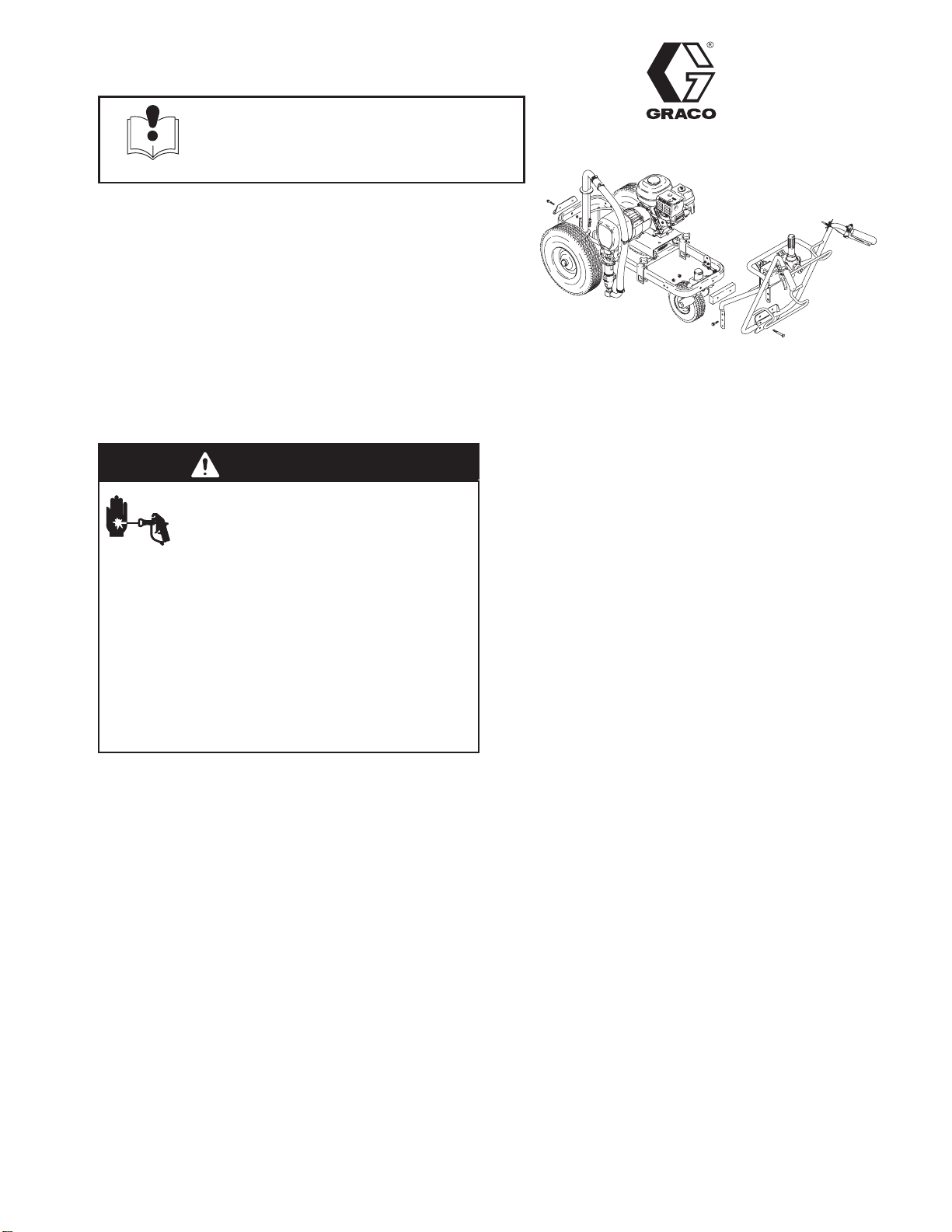
Remove Cables, Hoses, Wir-
ing, and Handle Assembly
Fig. 1. Remove cables, hoses, wiring, and handle from
LineLazer cart as outlined in the following steps.
8. Unfasten paint gun cable (58) from linestriper
trigger (19). Remove spring clips (130) to free
cable from linestriper handle (24). Move cable and
clips aside for reassembly later.
9. Unfasten swivel wheel cable (102) from actuator
lever (101). Remove spring clips (130) to free
cable from linestriper handle (24). Move cable and
clips aside for reassembly later.
10. Separate gun hose (17) from coupled hose (11).
Move gun hose aside for rerouting during reas-
sembly.
11. Unfasten coupled hose (25) from pressure
control (2). Move aside for rerouting later.
12. Disconnect power cable (62) from pressure
control (2). Move aside for rerouting later.
13. Remove mounting bracket (103), brake rod (105),
attaching hardware: two flange screws (54) and
two lock nuts (55).
GRACO INC. P.O. BOX 1441 MINNEAPOLIS, MN 55440–1441
ECOPYRIGHT 1999, GRACO INC.
Graco Inc. is registered to I.S. EN ISO 9001
2308944
Reversible Handle Kit
14. Remove linestriper handle (24), four cap
screws (69), four lock nuts (68), and tie
straps (129). Carefully set aside assembled line–
striper handle (24) and pressure control (2).
15. Loosen two knobs (127) and slide out assembled
gun hose (17), flex gun (40), and support
bracket (128).
Note: Raise the LineLazer and place a support under
and near the front end of the cart frame (126) before
removing the caster wheel assembly(118) in the follow-
ing steps.
16. Free detent arm (118ac) from cable (102) by
loosening and removing wire stop (117) from
cable.
17. Loosen and remove two cap screws (143) and two
lock nuts (68)
18. Remove caster wheel assembly (118) and front
caster bracket (124).
Fig. 1
58
24
130 55
17
102
8897A
130
130
A
A
B
B
19
101
25
2
129
69
68
62
105 103 54
127
68
102(Ref)
118
117,118ac
143
124
126
128
40
11
308944 3
Reversible Handle Kit
Reposition Adjuster Disk
Reposition the adjuster disk (118af) to allow proper
release of swivel wheel when the reversible handle kit
is installed.
1. Fig. 2. Remove cap screw (118as) and hardened
washer (118ar) from caster wheel assembly (118).
2. Rotate adjuster disk (118at) 180and install cap
screw (118as) and hardened washer (118ar)
through the second hole on the adjuster disk.
Fig. 2 8838A
AA
A–A
Top View
118as 118ar
118ac
118(Ref)
118at
Re–install Cables, Hoses,
Wiring, and Handle Assy
Fig. 1. and Fig. 3. Assemble the swivel wheel kit
according to the following steps.
Note: Make sure the LineLazer has a support under
and near the front end of the cart frame (126) before
starting the assembly.
1. Carefully line up caster wheel assembly (118),
spacer plate (201), assembled linestriper
handle (24) and pressure control (2) with front of
cart.
Note: Remove one screw and nut from front of cable
bracket (37) before proceeding with step 2.
2. On both sides of cart, loosely install one cap
screw (204) and one lock nut (203) through the
middle hole of front support on handle (24) and the
cart frame.
3. Loosely install and two flange screws (202) and
two lock nuts (203) through middle holes of bottom
bracket on handle (24), spacer plate (201), and
front of cart.
Note: For higher or lower handle height use either the
top or bottom hole on front support and bottom bracket
of handle (24).
4. Tighten screws (202) and lock nuts (203).
5. Install caster bracket (124) on rear of linestriper
frame (126) with two cap screws (143) and two
lock nuts (68).
6. Fig. 4. Install compression spring (116) and wire
from cable (102) to detent arm (118ac). Insert wire
into wire stop (117) and tighten. See Cable Adjust-
ment on page 4.
7. Fig. 3. Rotate assembled gun hose (17), flex gun
(40), and support bracket (128) 180. Install on
right side, looking toward back of linestriper. Tight-
en two knobs (127).
8. Fig. 1. Install mounting bracket (103), brake rod
(105) with attaching hardware two flange screws
(54) and two lock nuts (55).
9. Fig. 3. Reroute power cable (62) and connect to
pressure control (2).
10. Loosen displacement pump (80), swivel union
(27c) and rotate coupled hose (25) to front. Attach
to pressure control (2). Tighten swivel union and
displacement pump.
11. Fig. 1. Reroute gun hose (17) and attach to
coupled hose (11).
12. Reroute swivel wheel cable (102) and attach to
actuator lever (101). Secure cable to linestriper
handle (24) using spring clips (130).
13. Reroute paint gun cable (58) and attach to line–
striper trigger (19). Secure cable to linestriper
handle (24) using spring clips (130).
4308944
Reversible Handle Kit
Fig. 3
201
203
202
204 Ref
No. Part No. Description Qty
240714 KITASSY, reversible handle Ref
201 194412 . PLATE, spacer 1
202 110837 . SCREW, flange, hex 2
203 111040 . NUT, lock, nylock 4
204 100454 . SCREW, cap, hex hd 2
Kit Parts List 8922A
40
118
24
2
143 124
68
27c80 25
127
126
128
37
17
62
101,102,130
19
58,130
Cable Adjustment
Adjust the cable as follows:
1. Fig. 4. Make sure cable is routed between the top
of sprayer frame and underneath the motor mount
plate
2. Check that cable is snug and cable nut (A) under
spring is tight. Extend cable wire and draw tight in
wire stop (7). Tighten wire stop screw.
3. Check that release lever frees wheel to turn.
Readjust cable if necessary.
Fig. 4
117
A
8835A
102 116 118ac
Graco Phone Number
TO PLACE AN ORDER
, contact your Graco distributor, or call this number to identify the distributor closest to you:
1–800–690–2894 Toll Free.
All written and visual data contained in this document reflects the latest product information available at the time of publication.
Graco reserves the right to make changes at any time without notice.
Sales Offices: Minneapolis, Detroit
Foreign Offices: Belgium, England, Korea, France, Germany, Hong Kong, Japan
GRACO INC. P.O. BOX 1441 MINNEAPOLIS, MN 55440–1441
http://www.graco.com
PRINTEDIN USA 308944 March 1999

Other manuals for LineLazer 3900

1

This manual suits for next models

2

Other Graco Industrial Equipment manuals

Graco SERIES F User manual

Graco

Graco SERIES F User manual

Graco C27130 Operation manual

Graco

Graco C27130 Operation manual

Graco PR70 Series User manual

Graco

Graco PR70 Series User manual

Graco Reactor 2 E-30 Instruction Manual

Graco

Graco Reactor 2 E-30 Instruction Manual

Graco Road Lazer 241880 User manual

Graco

Graco Road Lazer 241880 User manual

Graco 24E656 User manual

Graco

Graco 24E656 User manual

Graco 236-931 Operation manual

Graco

Graco 236-931 Operation manual

Graco Viscount I Parts list manual

Graco

Graco Viscount I Parts list manual

Graco 24W159 User manual

Graco

Graco 24W159 User manual

Graco LineLazer III 200HS Instruction Manual

Graco

Graco LineLazer III 200HS Instruction Manual

Graco 244632 Operation manual

Graco

Graco 244632 Operation manual

Graco Fire-Ball 222073 User manual

Graco

Graco Fire-Ball 222073 User manual

Graco Xtreme Mix 185 Instruction Manual

Graco

Graco Xtreme Mix 185 Instruction Manual

Graco 223627 Operation manual

Graco

Graco 223627 Operation manual

Graco HydroShield WABH00 Parts list manual

Graco

Graco HydroShield WABH00 Parts list manual

Graco ProMix PD3K Plus Instruction Manual

Graco

Graco ProMix PD3K Plus Instruction Manual

Graco 240209 Operation manual

Graco

Graco 240209 Operation manual

Graco XP 26C051 Parts list manual

Graco

Graco XP 26C051 Parts list manual

Graco 234413 User manual

Graco

Graco 234413 User manual

Graco President K Series Operation manual

Graco

Graco President K Series Operation manual

Graco LineLazer III 200HS Instruction Manual

Graco

Graco LineLazer III 200HS Instruction Manual

Graco 238-024 Operation manual

Graco

Graco 238-024 Operation manual

Graco Compact Twin Flow User manual

Graco

Graco Compact Twin Flow User manual

Graco ProMix 239738 User manual

Graco

Graco ProMix 239738 User manual

Popular Industrial Equipment manuals by other brands

ABB SCK operating instructions

ABB

ABB SCK operating instructions

XINDA WYJ140 Series operating manual

XINDA

XINDA WYJ140 Series operating manual

emmeti SFERA GAS installation manual

emmeti

emmeti SFERA GAS installation manual

WAGNER Basic 8000 Translation of the original operating manual

WAGNER

WAGNER Basic 8000 Translation of the original operating manual

nord SK CI5-230/006-C datasheet

nord

nord SK CI5-230/006-C datasheet

POWERTEX PGT-S2 user manual

POWERTEX

POWERTEX PGT-S2 user manual

elco Wire Wizard installation instructions

elco

elco Wire Wizard installation instructions

Eaton Cooper Power VFI SF6 Installation, operation and maintenance instructions

Eaton

Eaton Cooper Power VFI SF6 Installation, operation and maintenance instructions

Shini SG-24N manual

Shini

Shini SG-24N manual

HALDER EH 22350 instructions

HALDER

HALDER EH 22350 instructions

ABB HT563146 Operation manual

ABB

ABB HT563146 Operation manual

LOFTNESS Battle Ax 50 Series Owner's manual and parts book

LOFTNESS

LOFTNESS Battle Ax 50 Series Owner's manual and parts book

Regulus HSK 350 K P-B Installation and operation manual

Regulus

Regulus HSK 350 K P-B Installation and operation manual

Aventics LU6 operating instructions

Aventics

Aventics LU6 operating instructions

Sealey RE97XS05 instructions

Sealey

Sealey RE97XS05 instructions

ABB HT593556 Operation manual

ABB

ABB HT593556 Operation manual

PCB Piezotronics IMI SENSORS 080A130 Installation and operating manual

PCB Piezotronics

PCB Piezotronics IMI SENSORS 080A130 Installation and operating manual

IEMCA MASTER 880-VERSO P Manual for use and maintenance

IEMCA

IEMCA MASTER 880-VERSO P Manual for use and maintenance

manuals.online logo
manuals.online logoBrands
  • About & Mission
  • Contact us
  • Privacy Policy
  • Terms and Conditions

Copyright 2025 Manuals.Online. All Rights Reserved.