6
© 2020 Pressure Systems International, Inc.
All rights reserved worldwide.
T010-01 Rev 10-20
TireView LIVE™ Installation Manual
Mounting Options
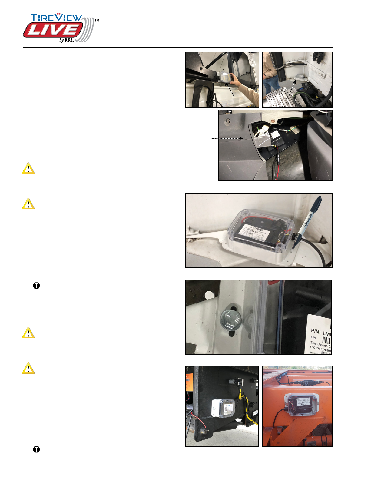
TireView Live Mounting Locations
The TireView LIVE sending unit can be mounted on
the tractor/truck or trailer.
Tractor/Truck Mounting
1. Identify a suitable mounting location for the
TireView LIVE sending unit on the Tractor/Truck.
See Figure 1.
Option 1: External mounting requires TireView
LIVE sending unit to be in weatherproof enclosure.
Option 2: In-cab mounting does not require
weatherproof enclosure. TireView LIVE sending
unit may be secured with 2-sided foam tape or
hook and loop fastener.
CAUTION
Do not mount TireView LIVE sending unit where tires
can throw debris onto enclosure as this could cause
damage.
CAUTION
Make sure location is suitable to route power supply
cable to the TireView LIVE sending unit.
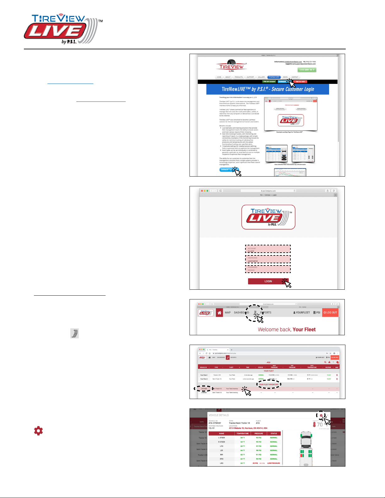
2. Use the TireView LIVE weatherproof enclosure as
a template to mark for drilling the mounting holes
and use a 3/8” drill bit to drill two holes (6 5/8”
apart). See Figure 2.
3. Use the supplied bolts, washers and locknuts to
attach the TireView LIVE weatherproof enclosure
to the tractor/truck.
Torque to 8-10 ft.-lbs. See Figure 3.
Trailer Mounting
1. Identify a suitable mounting location for the
TireView LIVE weatherproof enclosure on the
Trailer. See Figure 4.
CAUTION
Do not mount TireView LIVE weatherproof enclosure
where tire can throw debris onto enclosure as this
could cause damage.
CAUTION
Make sure location is suitable to route power supply
cable to the unit.
2. Use the TireView LIVE weatherproof enclosure as
a template to mark for drilling the mounting holes
and use a 3/8” drill bit to drill two holes (6 5/8”
apart). See Figure 2.
3. Use the supplied bolts, washers and locknuts to
attach the TireView LIVE weatherproof enclosure
to the trailer.
Torque to 8-10 ft.-lbs. See Figure 3.
Figure 1: Suitable mounting locations (Tractor/Truck)
Figure 4: Suitable mounting locations (Trailer)
Option 1: Cross-brace Option 1: Cross-brace
behind cabbehind cab
Eg: Rear side of lift gateEg: Rear side of lift gate
housing with access tohousing with access to
battery boxbattery box
Eg: ChassisEg: Chassis
or frameor frame
crossmembercrossmember
Option 1: Lower gusset Option 1: Lower gusset
for side deectorfor side deector
Option 2 : behind center Option 2 : behind center
console in truck cabconsole in truck cab
Figure 2: Mark drilling template
Figure 3: Mount using supplied hardware
Access
below center
console
cover