PA PR-4 User manual

PALLETIZER
Model PR-4
Model PR-5
Model PR-6
Model PR-8
Model PR-10
INSTALLATION
&OPERATING
INSTRUCTION
MANUAL
Form No. 1114 3-08
®

2
P/A INDUSTRIES INC.
SAFETY INSTRUCTIONS . . . . . . . . . . . . . . . . . . . . . . . . 3
PALLET REEL DESCRIPTION . . . . . . . . . . . . . . . . . . . 3
BASE........................................ 3
CONTROLARM .............................. 3
DRIVE ............. ......................... 3
DIMENSIONS & SPECIFICATIONS . . . . . . . . . . . . . . . 4
UNITINSTALLATION........................... 5
Receiving................................. 5
Assembly.................................. 5
Base Arm Position Drawing. . . . . . . . . . . . . . . . . . 5
ElectricalPower............................5
Safety Interlock Circuit . . . . . . . . . . . . . . . . . . . . . . 6
ControlHeadPosition.......................6
TablePosition ............................. 6
Distance from Forming Equipment . . . . . . . . . . . 6
OPERATIONSSTART-UP........................6
Positioning................................ 6
Clockwise/Counter-Clockwise
(CW/CCW) Rotation . . . . . . . . . . . . . . . . . . . . . 6
Loading...................................7
Base Arm Adjustment . . . . . . . . . . . . . . . . . . . . . . . 7
Control Head Height Adjustment . . . . . . . . . . . . . . 7
PALLETIZER
Pre-Test...................................7
Counter-Weight Tension System . . . . . . . . . . . . . 8
OptionalCoil-lock.......................... 8
Trial fit the Coil-Lock . . . . . . . . . . . . . . . . . . . . . . . 8
MAINTENANCE................................8
Cleaning.................................. 8
Lubrication................................ 8
ElectricMotor..............................8
TROUBLESHOOTING...........................8
Table Does Not Rotate or Tight Loop . . . . . . . . . . 8
TableDoesNotStop........................ 9
Table Does Not Rotate Fast Enough . . . . . . . . . . 9
Erratic Motion in Drum Roller . . . . . . . . . . . . . . . . 9
Drum Roller Hitting Tight Loop . . . . . . . . . . . . . . 9
PALLETIZER PR-4 and PR-5 . . . ................ 10
PALLETIZERPR-6............................ 11
PALLETIZER PR-8 and PR-10 . . . . . . . . . . . . . . . . . . 12
CONTROL ARM ASSEMBLY . . . . . . . . . . . . . . . . . . . . 13
GUIDE DRUM ASSEMBLY . . . . . . . . . . . . . . . . . . . . . . 14
PALLET REEL STRAIGHTENER . . . . . . . . . . . . . . . . . 15

3
SAFETY INSTRUCTIONS
Throughout this manual, each section will emphasize
certain safety precautions that should be adhered to by all
personnel who are setting up, operating, maintaining, and
repairing your P/A Pallet Reel.
It is impossible to mention all the precautions that should
be taken in a working environment, therefore, it is YOUR
responsibility to “BE ALERT” while working on, or
operating this equipment.
1) DO NOT OPERATE THE MACHINE UNTIL THE
MANUAL HAS BEEN READ.
2) STAY CLEAR OF ALL MOVING PARTS.
3) STOP MACHINE BEFORE CLEANING.
4) DISCONNECT MACHINE BEFORE OILING OR
PERFORMING MAINTENANCE.
5) MAKE SURE MACHINE IS PROPERLY GROUNDED.
6) BE AWARE THAT ONLY QUALIFIED PERSONNEL
SHALL OPEN ELECTRICAL CABINET.
7) DO NOT PUT HANDS UNDER PLATFORM TO
ROTATE MANUALLY.
PALLET REEL DESCRIPTION
The Pallet Reel pallet decoiler is specifically designed to
automatically feed strip stock directly from a palletized stack
of coils. The Pallet Reel series are designed and built to
PALLETIZER
CAUTION - PERSONAL INJURY MAY RESULT IF THE FOLLOWING
SAFETY PRECAUTIONS ARE NOT OBSERVED
handle a variety of stock widths, thickness and stacked
weights. This is accomplished by three major components
of the Pallet Reel system: Base, Control Arm, and Drive.
BASE
The BASE of the Pallet Reel is a series of urethane cast-
ers equally spaced. These casters are positioned on the
outside edge of the rotating top to insure the unit will rotate
smoothly under great loads. This design is the reason your
Pallet Reel can effectively handle up to 10,000 Lbs.
(depending on model) and still be easily positioned on line.
This low profile design also saves on valuable shop floor
space.
CONTROL ARM ASSEMBLY--
The CONTROL ARM is the most important and critical
element to your horizontal Pallet Reel. It guides the
material, controls the turntable speed, and provides
consistent and constant material tension to your press or
forming equipment. This unique design to the Pallet Reel
is the most effective available to the industry.
It has a hollow,lightweight feed pulley that slides
horizontally on linear bearings so that the weight of the
drum is supported. Weights are attached to the drum to
minimize their inertia affect and to give constant tension to
the material being controlled. With this system, it is
possible to achieve very accurate tensioning of thin and
thick stock without bending or distortion by adding or
subtracting weights.
DRIVE
A high torque, AC motor, with a right angle worm gear
reducer,drives a solid rubber wheel against the inside rim
of the table.
Linear Drum
Assembly
Table
Table Rim
Drive Wheel
Motor
Base
Mounting
Bracket
Control
Assembly
Tension/LC
Arm Assembly
Extra Weights

4
PALLETIZER
Model PR4 PR5 PR6 PR8 PR10
Pallet Coil Weight 4000 Lbs. 5000 Lbs. 6000 Lbs. 8000 Lbs. 10000 Lbs.
Table Diameter 42” 52”
Overall Width Range 46–63” 56–73”
Coil Stacking Height 36”
Table RPM - Standard 0–12
-Optional 0–24
Stock Width - Standard 0–6”
-Optional 0–9” 0–12” 0–15” 0–18” 0–24”
Stock Thickness Range .004–.065”
ACDrive Motor, HP 3/4 1 1-1/2 (High Speed 2) 2 3
Electrical Input 120 VAC, 1 Phase, 60 Hz 240 VAC, 1 Phase, 50/60 Hz
(Optional Voltage Available) 230 VAC, 1 Phase, 50/60 Hz 400V, 50 Hz and 460V, 60 Hz
SPECIFICATIONS
DIMENSIONS
64” Max. 6” Std.
20”
Table Diameter
6 – 36” Adjustment
24.5–41.5” Max. Extension
Overall Width Range

5
UNIT INSTALLATION
Receiving
Inspect the Pallet Reel for shipping damage immediately
upon receipt. If damage is observed, make a note of the
damage on the carrier’s delivery receipt before signing.
Then notify your local carrier terminal and P/A Industries.
The Pallet Reel is shipped disassembled and packaged for
protection during transit. Care should be taken during
unpacking so that all paper work and parts are collected
and accidental damage is avoided. The stretch wrap
around the head assembly should be removed after
assembly, not before.
Assembly
The Control Head Assembly Base Arm must be inserted
into one of the two holes provided in the leg (Figure 1). For
shipment, a rubber band is placed around the Base Arm
Tightening Assembly. Remove this rubber band. Select
which mounting hole to use by identifying the job to be run.
General guidelines are as follows:
The following drawing displays Control Head capacity
dimensions:
Use Lower Mounting Hole (Figure 2) for:
•Very narrow strip stock less then 2” where parallel
pull-off is preferred.
•Coil stack height does not exceed 30”.
Use Upper Mounting Hole (Figure 3) for:
•Tall coil stacks where maximum elevation of Guide
Drum Assembly is required.
•Wider strip materials where near parallel
UN-winding is not a concern.
Lift the Control Head Assembly from the tabletop, leave
wrapped until inserted, and slide the base arm into the
selected mounting hole. The Base Arm slides in and out of
the leg to allow adjustable clearance for different size
pallets rotating on the tabletop.
Position Base Arm to desired location and tighten the one
hex head bolt to wedge the base arm in a fixed position.
If using the upper mounting hole, simply unthread the
wedge-tightening bolt and reinstall the assembly at the
upper hole.
Base arm position drawing
Remove stretch wrap protecting the Control Head
Assembly and remove corrugated retainers located in
Weight Channels.
Electrical Power
The electrical power requirement of your Pallet Reel is
clearly marked on the Control Box and on the tag attached
to the end of the power cord.
Models requiring 220V (and up) power are shipped without
asupply power connection.
Please ensure the Pallet Reel is connected to the correct
power source and that all wire, cable, etc. are installed in
accordance with all prevailing codes. Refer to schematic
for proper fuse or circuit breaker size.
PALLETIZER
Lower Mounting Hole
Table
Arm
Figure 2
Upper Mounting Hole
Upper Position
Lower Position
Figure 3
Figure 1
Table
Arm
Safety InterlockCircuit
Each Pallet Reel is equipped with a pre-wired Safety
Interlock Circuit.
NOTE: FAILURE TO ENSURE OPERATIVE INTERLOCK CIRCUIT
CAN RESULT IN PERSONNEL INJURY TO PRODUCTION
EQUIPMENT, AND VOIDING OF THE PALLET REEL WARRANTY.

6
You may estimate this distance before positioning the
Pallet Reel by pulling off a strip from the coil to be used,
manually twist to 1/4 turn and measure the distance
needed to achieve an easy transition. Place the Control
Head of the Pallet Reel at this approximate measured
distance from the forming equipment.
OPERATIONS START-UP
Before beginning production with the Pallet Reel, complete
the following steps to ensure a safe and successful start-up.
Positioning (Refer to Figure 4))
Make sure the Pallet Reel is oriented so that the Control
Head Mast is aligned with the feed entry to the forming
equipment. Also, make sure that the table is placed to
accommodate the wind direction of the coils to be fed.
It is best to check positioning at this stage rather than later
when the pallet load is on the turntable.
Clockwise/Counter-Clockwise (CW/CCW) Rotation
Examine the coils to be fed to determine the unwind
direction. Determine if the coil will rotate in a CW direction
or a CCW direction.
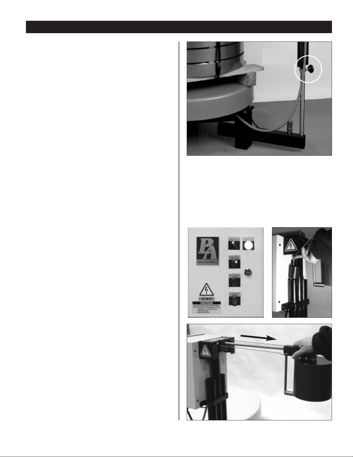
Set the CW/CCW Switch on the Motor Control Box to the
appropriate setting. Change setting of this switch only
when table rotation has stopped.
Loading
Load the pallet of coiled materials, being careful not to
strike the Control Head Assembly. The top portion of the
Control Head can be swiveled to the left or right to position
it away from the loading side.
Center these coils on the turntable with eyesight accuracy.
The Pallet Reel can tolerate a small amount of off-center
loading, however too great a miss-alignment will create an
oscillating rotation of the coils which will cause uneven
feeding and uneven loading on the Pallet Reel frame and
tabletop.
Be aware of the difference between centering the coil and
centering the pallet. Coils are not always centered on the
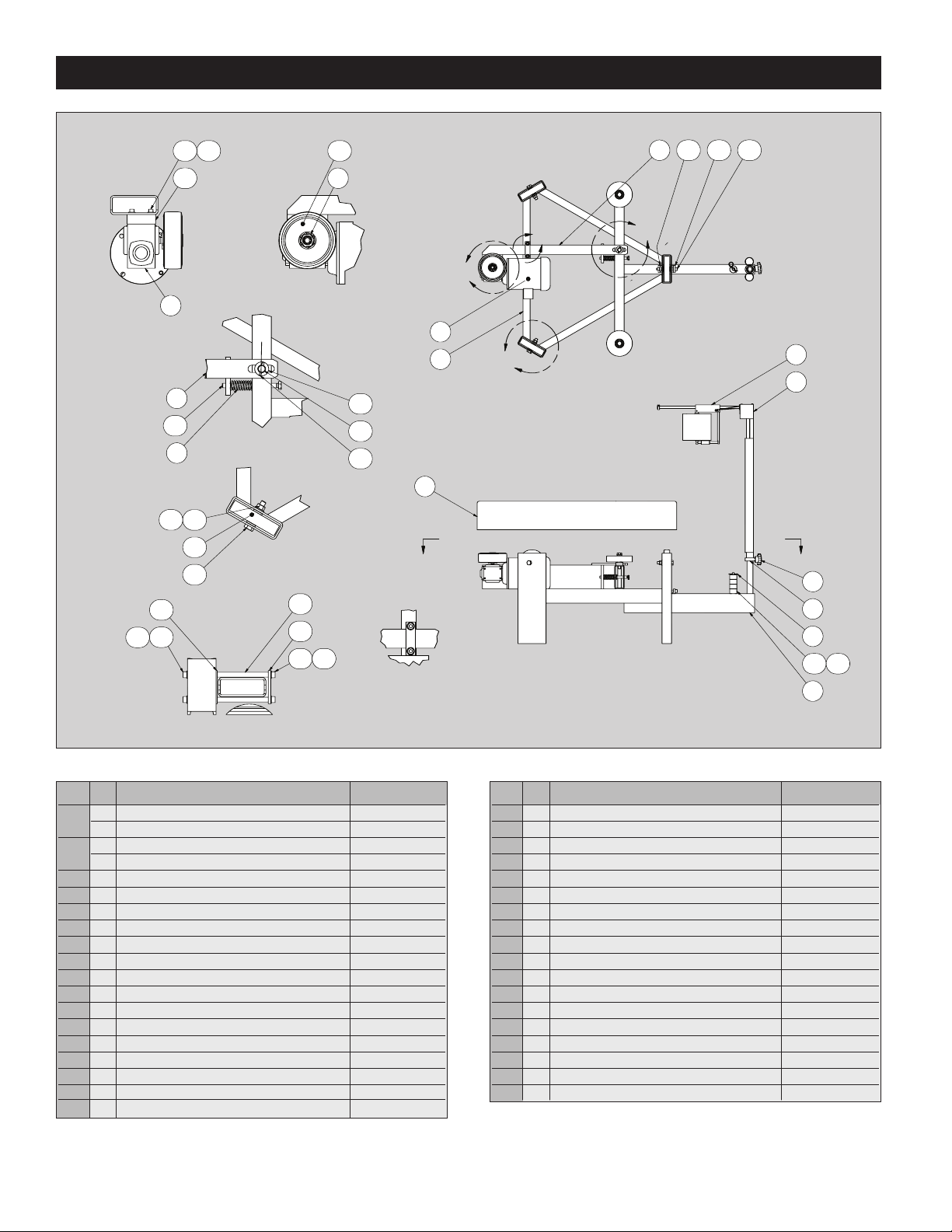
PALLETIZER
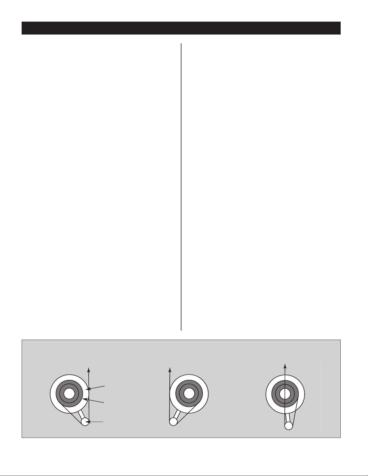
Position 1 – Right Position 2 – Left Position 3 – Center
Figure 4
Control Head
Material
Table
Material Feed
Direction
The Safety Interlock Circuit will allow you to shut down the
production equipment used in conjunction with the Pallet
Reel if the Pallet Reel detects a Drive Fault or a material
tight loop condition. There is a pre-wired circuit in the
Pallet Reel that requires connection to associated
production equipment.
Control Head Position (Figure 4)
The Control Head should always be aligned with the
production equipment feed entry so that the strip loop will
follow a straight run from the Pallet Reel Guide Drum
directly to the forming equipment entry. This alignment can
be done by visual line of sight from Control Head Mast to
feed entry.
Table Position (Figure 4)
The diagrams demonstrate the various material flow
options available. Although feeding the coil strip directly
back over the coil stack (Position 3) is a feasible option, it
is not highly recommended. Unwinding off to either side is
preferred since this reduces the opportunity for tangling
the strip on the coil stack and damaging the strip edge.
Also, offcenter feeding will allow a more parallel pull of
the strip from the coil.
Distance from Forming Equipment
The distance required between the Pallet Reel and the
forming equipment will depend on the characteristics of the
coil strip being used. There is no specific rule or formula
for this determination.
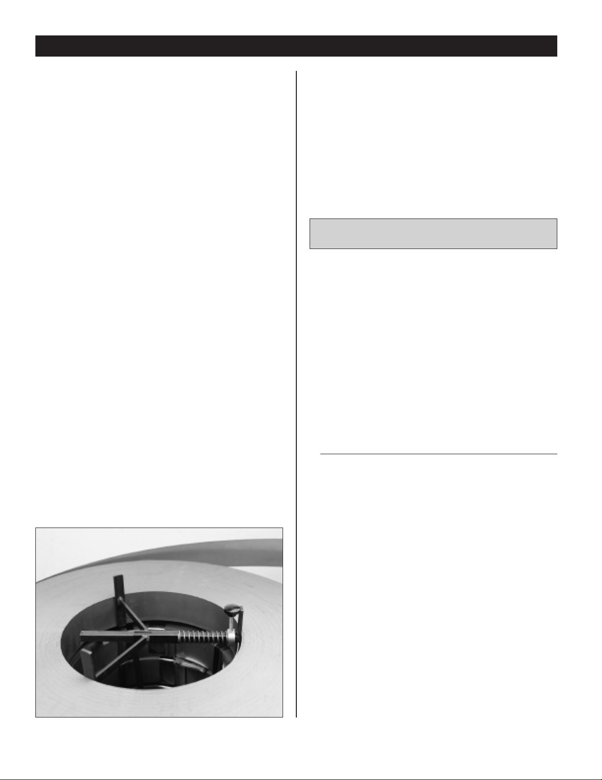
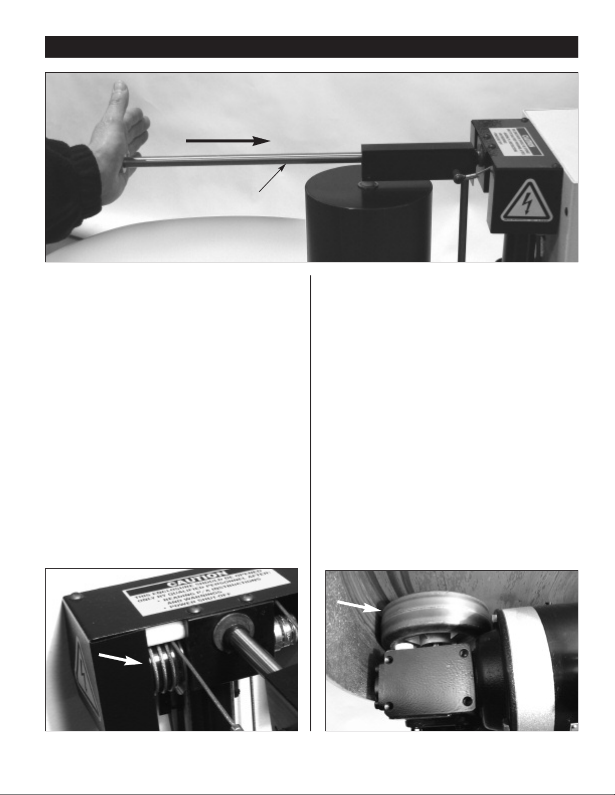
The strip material passes around the Pallet Reel Guide
Drum in a vertical position. As it feeds to the forming
equipment it will transition to a horizontal plane requiring
a1/4 turn or twist either to the left or right. The distance
required to achieve this twist easily,without kinking or
bending, will determine the position for the Pallet Reel.
Lighter, thinner materials will transition very easily and will
require little more than the 42" footprint of the Pallet Reel
itself. Heavier, thicker materials will require more loop
length to achieve the 1/4 twist and more set back will be
required.
You may estimate this distance before positioning the

7
PALLETIZER
pallets. When loading the Pallet Reel, it is best to look at
the coils first and then the pallet for centering purposes.
The load should be checked on all sides for centering and
to ensure no strapping or wrapping materials are hanging
down off the turntable.
Base Arm Adjustment
As described under Unit Installation (Page 5), the Control
Head Base Arm slides in and out of the leg, closer or
farther away from the table top, for the purpose of clearing
overhanging pallet corners.
This adjustment is made by loosening the two 3/8" nuts
at the Base Arm, positioning the arm as needed, and
retightening the two nuts. See BASE ARM POSITION
DRAWING on page 5.
Ensure that the Control Head Mast is sufficiently away from
the turntable to allow pallet corners to rotate past with
generous free clearance.
Control Head Height Adjustment (Figure 5)
The height of the Control Head is manually adjusted to
accommodate the decreasing height of the coil stack as
coils are fed into the forming equipment.
Loosen the black knob on the Control Head Mast and slide
the Control Head and Support Ring up or down as needed.
When in position, tighten the black knob to secure the
height position.
The Control Head should be adjusted so that the bottom of
the Guide Drum is parallel or somewhat higher than the
bottom edge of the top coil. This setting will allow the strip
to separate from the coil cleanly without hitting the wood
spacers under the coil.
As the coils are expended, the Control Head should be
manually lowered with the start of each new coil. For
narrower width strips, the Control Head may need to be
lowered only for every second or third coil. Experience will
be your best guide.
Pre-Test
Pre-Test operation of the Pallet Reel in the following manner:
1) Apply power to the control. Check “Power On” light is
illuminated.
2) Place Selector Switch Man/Auto in the Man position.
Depress the Jog button for table rotation.
3) Select CW/CCW switch and Motor Arm position for
proper directional setting.
4) Place Selector Switch Man/Auto in the Auto position.
5) Manually slide Guide Drum on Linear Rod. Observe
normal rotation of table (Figure 6)
6) Manipulate Guide Drum to different positions on Linear
Rod. Observe variable rotation speed of table.
Height
Adjustment
Knob
Figure 5
7) Release Guide Drum and allow it to fall back to off
position. Observe stopping of table rotation.
8) Extend the Guide Drum to the end of the Linear Rod
travel (Figure 7). Pull the Guide Drum further to activate
the Tight Loop fault. Check that the red Reset pushbutton
is illuminated indicating the Tight Loop fault. Reset the
Tight Loop fault by pushing inward on end of Linear Rod
then pushing the Reset pushbutton to distinguish the red
Reset pushbutton light (Figure 9 on page 9).
Figure 7
Figure 6

8
PALLETIZER
WARNING - DO NOT PERFORM ANY MAINTENANCE FUNCTIONS
WITHOUT FIRST DISCONNECTING POWER.
Figure 8
Counter-Weight Tension System
Begin operation with two weights on each cable. Pull cable
upwards through top of Weight Channel. Weights are easily
added or removed by positioning the Cable Toggle to slip
weights on or off.
Extra weights are stored on the Base Arm.
The weight on the cables should be sufficient to draw the
Guide Drum back to the off position when material demand
stops. Weight/tension should not be so great as to cause
undue stress on the stock or erratic motion of the Guide
Drum.
There is no formula or specific rule regarding how much
tension weight is needed. The goal is to balance the
weight of the strip loop with the back tension created by
the weights. Variables of strip width, thickness, loop
weight, feed length and press speed in a wide range of
combinations preclude a specific guiding rule.
Proper weight/tension balance is a matter of beginning with
two weights on each cable, running the forming equipment,
observing results at guide drum, and then adjusting
weights.
Optional Coil-lock(Figure 8)
The Coil-Lock will prevent the top coil from shifting off
center or pulling offthe coil stack as its weight diminishes
toward the inside diameter of the coil. The Coil-Lock fits
inside the open space at the core of the coil stack.
Trial fit the Coil-Lock.
Adjust the length and tension of the Coil-Lock by
positioning the Stop Collar at the appropriate location. The
Stop Collar is secured with the black knob. Set the Stop
Collar in a position that results in a Coil-Lock length slightly
longer than the I.D. dimension.
The Coil-Lock is compressed and placed in the open I.D.
space, then released to snugly press outward against the
coil.
The vertical legs of the Coil-Lock should connect with the
top coil and however many of the lower coils as strip width
will allow.
MAINTENANCE
Proper care and maintenance of the Pallet Reel will ensure
efficient operation and will extend service life of the
machine.
We recommend that upon receipt of your Pallet Reel,
arrangements be made to have your Pallet Reel added to
the plant maintenance schedule to ensure regular and con-
sistent maintenance attention.
Cleaning
Periodically wipe clean the surface areas of the Pallet Reel
including the tabletop, Control Box and Guide Drum.
Frequency of cleaning will be dictated by shop conditions
of dirt, dust, oil, etc.
Lubrication
•Edge Guide Roller - At 30-day intervals apply a thin
coat of light machine oil.
•Reduction Gear- Manufacturer’s product information
contains detail on this maintenance procedure. The
following summarizes lubrication change schedules.
Petroleum Synthetic
Lubricant Lubricant
Initial Change: 250 hours 1500 hours
Regular Change: 2500 hours 5000 hours
or six months
•Linear Shaft – At thirty-day intervals wipe polished rod
and spray with DTE Light Oil or other light machine oil.
Electric Motor
Manufacturer’sproduct information contains detail on care
of the motor.
TROUBLE SHOOTING
Table Does Not Rotate or Tight Loop
•Check Supply Power and Line Voltage.
•Check Circuit Breaker inside the motor control.
•Check if Reset Light on Control is illuminated. Reset by
either pushing Reset Button and/or pressing Linear Shaft
towards Motor Control (Figure 9).

9
PALLETIZER
Erratic Motion in Drum Roller
•Check that Drive Wheel is touching inside of table rim.
•Review number of Tension Weights placed on Tension
Cables. If Drum Roller is moving erratically back and
forth, this usually indicates too much weight. Remove
weights one at a time, from one side then the other until
balance in the Drum movement is achieved.
•Inspect cable windings on Pulley Cable Guide to be sure
that each winding is laying flat and that full rotation of
capstan is operative.
Drum Roller Hitting Tight Loop
•Machine Feed demands material faster than Pallet Reel
acceleration.
•Review speed requirements of job and speed capability
of the Pallet Reel to ensure compatibility.
•Review number of tension Weights placed on Tension
Cables. If Drum Roller is moving erratically back and
forth, this usually indicates too much weight. Remove
weights one at a time, from one side then the other until
balance in the Drum movement is achieved.
Figure 9
Linear Shaft
Figure 10
Figure 11
Table Does Not Stop
•Inspect cable windings on Pulley Cable Guide to be sure
that each winding is laying flat and that full rotation is
operative (Figure 10).
•Add more weight one at a time; from one side to the
other until weight is sufficient to pull Drum Roller back to
off position.
Table Does Not Rotate Fast Enough
•Check for stable Supply Power and correct line voltage.
•Visually check that Drive Wheel is touching inside of
table rim (Figure 11).
•Inspect cable windings on Pulley Cable to be sure that
each winding is laying flat and that full rotation of
Pulley Cable is operative.
•With power disconnected,inspect and feel inside
surface of tableside rim for grease or lubricant. Presence
of such material will cause Drive Wheel to slip, clean
both rim and Drive Wheel with a suitable cleaner.
Review speed requirements of job and speed capability
of the Pallet Reel to ensure compatibility.

10
PALLETIZER PR-4 and PR-5
SCALE 1 / 8
SECTION A-A
SCALE 1 / 8
DETAIL C
SCALE 1 / 4
DETAIL A
SCALE 1 / 4
DETAIL B
SCALE 1 / 4
DETAIL D
SCALE 1 / 4
A
A
C
A
B
D
5.22
5.14
5.235.25
5.13
5.1
5.20
5.21 5.24
1
2
5.26
5.12
5.27
5.3
5.31
5.8
3
4
5.7
5.30 5.28
5.18
5.17
5.19
5.295.28
5.8
5.9
5.15 5.16
5.5
5.2
5.6
5.11
5.10 5.29
5.4
Item Qty Description PartNumber
11 PR-4 Motor, 230/460 VAC 12125-111
1 PR-5 Motor, 230/460 VAC 12125-126
21 PR-4 Table, 42 in. 17934-01
1 PR-5 Table, 42 in. 17934-03
31Guide Drum Assembly,PR Refer to pg.14
41 Tension/LC Arm Assy, PR, 12 in. Travel 17962-20
5.1 1Trantorque, 1.5 OD x .625 ID 12028-55
5.2 1 Set Collar, 1.25 ID x 2.0 OD x 11/16 12441-108
5.3 1 Spring, Compression. 1 OD x .5 ID x 3 12442-77
5.4 1Reducer, Worm Gear, 15:1, 133, 56C 12445-143
5.5 1 Hairpin Cotter Pin, 1/8 Dia x 2.30 Long 12466-69
5.6 1Knob, 2.38 Dia x 3/8-16 Thd x .50 Long 14977-02
5.7 1 Base Weldment, Fixed Arm, PR, 42 in. 17920-03-04
5.8 1 Motor Arm, Fixed, PR, 42 in. (25.16) 17921-07
5.9 1 Arm Weldment, Outrigger, PR, 42 in. 17923-01
5.10 1Clamp, Outrigger,Threaded, Metric 17925-02
5.11 1 Clamp, Outrigger, Thru Hole 17926
5.12 1 Pin, Motor Arm 17927
5.13 1 Wheel, Drive, 6 in. Dia x 2 in. 17930-01
Item Qty Description PartNumber
5.14 5 Wheel Assembly, Idler, 5.415 Dia 17931-01
5.15 4 Collar, Counter Weight 17955-01
5.16 1 Rod, Counter Weight Storage 17964
5.17 2 Spacer, 1.0 OD x .56 ID x 5.24 Long 18233-04
5.18 1Strap, Hold Down, 3.5 x 1.0 x .25 Thick 18234-03
5.19 1 Wear Strip, 3.5 x 1.0 x .125 18234-04
5.20 1Spacer, Reducer, 1 in. Tigear 13Q Series 18783-01
5.21 4 5/16-18x2” Lg. SHCS Black 900031-16
5.22 5 1/2-13x3.0 Lg, Hex Hd, Cap Screw 908050-24
5.23 31/2-13, Hex Nut, Nylon Insert Locknut, Stain 942050SS
5.24 4 5/16, Flat Washer, SAE 958031
5.25 51/2, Flat Washer, SAE 958050
5.26 1 3/4, Flat Washer, SAE, ZP 959075
5.27 2 .187 Diax1 1/2 Lg, Roll Pin 972P18-12
5.28 4 M10, Washer, Flat, Reg, Zinc Plated Steel Din-125-M10
5.29 3M10x110mm Lg, SHCS, Black Din-912-M10x100
5.30 2 M10x25mm Lg, SHCS, Black Din-912-M10x25
5.31 1 M12x150mm Lg, Hex Hd SCR, Black Din-933-M12x150

11
PALLETIZER PR-6
SECTION A-A
SCALE 1 / 8
DETAIL A
SCALE 1 / 4
DETAIL B
SCALE 1 / 4
DETAIL C
SCALE 1 / 4
AA
A
B
C
3
2
8.25
8.14
8.13
8.27
8.17
8.20
8.10
8.188.20
8.4
6
7
8.3
8.1
8.11 8.12
8.6
8.28
8.2
8.21
8.9
8.22
8.8
8.24
8.7
41
9
10
8.15
8.29 8.23
8.16
8.26
1.21 8.20 8.108.5
5
Item Qty Description Part Number
11 Trantorque, 2.0 OD x 1.125 ID 12028-72
21PR-6 Motor,230/460 VAC 12125-125
1 PR-6HS Motor, 230/460 VAC 12125-128
31PR-6 Reducer, Worm Gear 12445-76
1 PR-6HS Reducer, Worm Gear 12445-154
41 Wheel, Drive, 10 Dia x 2.5 W x 2 in. Bore 17930-06
51Table, 52 in. 17934-02
61 Guide Drum Assembly, PR Refer to pg.14
71Tension/LC Arm Assy, PR 12 in. Travel 17962-20
8.1 1 Set Collar, 1.25 ID x 2.0 OD x 11/16 12441-108
8.2 1 Spring, Compression. 1 OD x .5 ID x 3 12442-77
8.3 1 Knob, 2.38 Dia x 3/8-16 Thd x .50 Long 14977-02
8.4 1Base Weldment, Fixed Arm, 52 in. Table 17920-02
8.5 1 Motor Arm, 42 in, Stationary 17921-09
8.6 1 Arm Weldment, Outrigger, PR 52 in. 17923-02
8.7 1 Clamp, Outrigger, Threaded, Metric 17925-02
8.8 1 Clamp, Outrigger, Thru Hole 17926
8.9 1 Pin, Motor Arm 17927
8.10 6 Wheel Assembly, Idler, 5.415 Dia 17931-01
8.11 4 Collar,Counter Weight 17955-01
Item Qty Description Part Number
8.12 1 Rod, Counter Weight Storage 17964
8.13 1Spacer,1in. Square x 4.25 18233-06
8.14 2 Spacer, 1.0 OD x .56 ID x 5.25 Long, mm 18233-07
8.15 1Wear Strip, 4.25 x 1.0 x .125 18234-05
8.16 1 Spacer, 1.0 OD x .56 ID x 5.24 Long 18234-06
1.21 2 1/2-13x2 1/2 Lg, Hex Hd, Cap Screw 908050-20
8.17 41/2-13x3 Lg, Hex Hd, Cap Screw 908050-24
8.18 4 1/2-13, Hex Nut, Nylon Insert Locknut, ZP 942050ZP
8.20 10 1/2, Flat Washer, SAE 958050
8.21 1 3/4, Flat Washer, SAE, ZP 959075
8.22 2 .187 Dia x 1 1/2 Lg, Roll Pin 972P18-12
8.23 2 M12, Washer, Flat, Reg, Zinc Plated Steel Din-125-M12
8.24 1M10x110mm Lg, SHCS, Black Din-912-M10x100
8.25 2 M10x20mm Lg, SHCS, Black Din-912-M10x20
8.26 2 M10x40mm Lg, SHCS, Black Din-912-M10x40
8.27 2 M12x120mm Lg, SHCS, Black Din-912-M12x120
8.28 1 M12x150mm Lg, Hex Hd Scr, Black Din-933-M12x150
8.29 2 M12, Hex Nut, Nylon Insert Lock Nut, ZP Din-985-M12
94 3/8-16 x 2 1/2 Lg, SHCS, Black 900038-20
10 43/8, Flat Washer 958038

12
PALLETIZER PR-8 and PR-10
SECTION A-A
SCALE 1 / 8
DETAIL A
SCALE 1 / 4
DETAIL B
SCALE 1 / 4
DETAIL C
SCALE 1 / 4
A A
A
B
C
41
3
2
8.1
8.4
7
6
8.11
8.19
8.21
8.20 8.21
8.9
8.28
8.8
8.26
8.17
8.15
8.16
8.27
8.25
8.14
8.30 8.24
8.22
8.23
8.10
8.29
8.2
8.6
910
8.13 8.13 8.3
5
8.5
Item Qty Description Part Number
11Trantorque, 2.0 OD x 1.125 ID 12028-72
21 PR-8 Motor 12125-128
1PR-8HS Motor 12125-128
1 PR-10 Motor 12125-106
1 PR-10HS Motor 12125-106
31PR-8 Reducer 12445-76
1 PR-8HS Reducer 12445-154
1PR-10 Reducer 12445-85
1 PR-10HS Reducer 12445-156
41Wheel, Drive, 10 Dia x 2.5 W x 2 in. Bore 17930-06
51 Table, 52 in. 17934-02
61 Guide Drum Assembly, PR Refer to pg.14
71Tension/LC Arm Assy, PR 12 in. Travel 17962-20
8.1 1 Set Collar, 1.25 ID x 2.0 OD x 11/16 12441-108
8.2 1Spring, Compression. 1 OD x .5 ID x 3 12442-77
8.3 1 Hairpin Cotter Pin, 1/8 Dia x 2.30 Long 12466-69
8.4 1 Knob, 2.38 Dia x 3/8-16 Thd x .50 Long 14977-02
8.5 1Base Weldment, PR-8/10 17920-04
8.6 1 Motor Arm, 42 in, Stationary 17921-09
8.7 1 Arm Weldment, Outrigger, PR 52 in. 17923-02
8.8 1 Clamp, Outrigger, Threaded, Metric 17925-02
8.9 1 Clamp, Outrigger, Thru Hole 17926
8.10 1 Pin, Motor Arm 17927
Item Qty Description Part Number
8.11 10 Wheel Assembly, Idler, 5.415 Dia 17931-01
8.12 4 Collar, Counter Weight 17955-01
8.13 1 Rod, Counter Weight Storage 17964
8.14 1 Spacer, 1 in. Square x 4.25 18233-06
8.15 2 Spacer, 1.0 OD x .56 ID x 5.25 Long, mm 18233-07
8.16 1 Wear Strip, 4.25 x 1.0 x .125 18234-05
8.17 1Spacer,1.0 OD x .56 ID x 5.25 Long 18234-06
8.18 21/2-13x2 1/2 Lg, Hex Hd, Cap Screw 908050-20
8.19 4 1/2-13x5.0 Lg, Hex Hd, Cap Screw, GR5, ZP 908050-40GR5ZP
8.20 4 1/2-13, Hex Nut, Nylon Insert Locknut, ZP 942050ZP
8.21 14 1/2, Flat Washer, SAE 958050
8.22 1 3/4, Flat Washer, SAE, ZP 959075
8.23 2.187 Diax1 1/2 Lg, Roll Pin 972P18-12
8.24 2M12, Washer,Flat, Reg, Zinc Plated Steel Din-125-M12
8.25 2 M12x120mm Lg, SHCS, Black Din-912-M12x120
8.26 2 M12x20mm Lg, SHCS, Black Din-912-M12x20
8.27 2 M12x40mm Lg, SHCS, Black Din-912-M12x40
8.28 1M10x150mm Lg, Hex Hd SHCS, Black Din-933-M10x150
8.29 1M12x150mm Lg, Hex Hd Scr,Black Din-933-M12x150
8.30 2 M12, Hex Nut, Nylon Insert Lock Nut, ZP Din-985-M12
943/8-16 x 2 1/2 Lg, SHCS, Black 900038-20
10 4 3/8, Flat Washer 958038

13
CONTROL ARM ASSEMBLY
21
19
3
14
6
1
4
16
15
10
8
25
5
18
20
27
26
4
2
13
7
23
9
24
12
11
17
22
Item Qty Description Part Number
11Coupling, .25 Bore, Adj Slip 12028-77
21 Limit Switch, Micro, 10A @ 240 VAC 12031-23
31 Washer, Rubber, .5 ID x 1.062 OD x .093 12434-59
42 Washer, Thrust, .255 ID x .437 OD x 1/16 12434-60
51Plunger,Ball, M8 x 22mm Long 13379-70
61Potentiometer,3-Turn, 10K 14946-16
71 Sheave, 1.0 Dia x 1/8 Rope Dia 14963-60
81 Wire Rope Guide 17945
91 Wire Rope Guide 17945-03
10 1 Pulley, Cable Guide, Metric 17946-03
11 1Shaft, Pulley, Cable Guide 17947-01
12 1 Mast, Tubular Weldment 17948-02
13 1 Mounting Block, Upper, Control Mast, Metric 17950-05
14 1 Cable, 30 in Long, w/Loop Ends 17954-01
Item Qty Description Part Number
15 1Cable, 42 in Long, w/Loop Ends 17954-02
16 2 Collar, Counter Weight, 1 in 17955-01
17 1 Pin, Cable Pulley Guide 17957
18 2 Pin, Cable Counter Weight 17959
19 1Linear Shaft, 1/2 OD x 20 in 17961-01
20 1Cover,Tension/Loop Control Arm 17963-04
21 2 Collar, Modified, .501 ID 18305-03
22 2 M2x8mm Lg, Cheesehdscr, Raised, Steel-Plat Din-7985-M2x8
23 1 M4x20mm Lg, FHSCS, Black Din-7991-10-M4x20
24 1 M5x25mm Lg, FHSCS, Zinc Plated Din-7991-M5x25
25 1M5x30mm Lg, FHSCS Din-7991-M5x30
26 1M5x10mm Lg, Sock Set Scr,Cup Pt, Black Din-916-M5x8
27 4 M5x10mm Lg, BHCS, Black Din-9427-M5x10

14
GUIDE DRUM ASSEMBLY
2
14
13
4
9
3
3
6
3
8
1
5
1
10.2
10.1
10.2
711
12
Item Qty Description Part Number
12Retaining Ring, External, 3/8 Shaft 12013-61
22 Linear Ball Bearing, .500 Dia 15433-24
31 Drum, Roller Guide Assy, 6 in. Drum 17935-01
1Drum, Roller Guide Assy, 9 in. Drum 17935-02
1 Drum, Roller Guide Assy, 12 in. Drum 17935-03
1 Drum, Roller Guide Assy, 15 in. Drum 17935-06
1 Drum, Roller Guide Assy, 18 in. Drum 17935-04
1 Drum, Roller Guide Assy, 24 in. Drum 17935-05
1 Drum, Roller Guide Assy, 6 in. Drum, Urethane 17935-11
1 Drum, Roller Guide Assy, 9 in. Drum, Urethane 17935-12
1Drum, Roller Guide Assy, 12 in. Drum, Urethane 17935-13
1 Drum, Roller Guide Assy, 15 in. Drum, Urethane 17935-16
1 Drum, Roller Guide Assy, 18 in. Drum, Urethane 17935-14
1 Drum, Roller Guide Assy, 24 in. Drum, Urethane 17935-15
41 Bearing Block, Linear Guide 17938
51 Axle, Roller, Edge Guide 17939-01
61 Spacer, Roller 17940-01
71Support Bar, Axle, 6 in Drum 17941-01
1 Support Bar, Axle, 9 in Drum 17941-02
1 Support Bar,Axle, 12 in Drum 17941-03
1 Support Bar, Axle, 15 in Drum 17941-06
1 Support Bar, Axle, 18 in Drum 17941-04
1 Support Bar,Axle, 24 in Drum 17941-05
1 Support Bar, Axle, 6 in Drum Urethane 17941-01
1 Support Bar, Axle, 9 in Drum Urethane 17941-02
1 Support Bar,Axle, 12 in Drum Urethane 17941-03
1 Support Bar, Axle, 15 in Drum Urethane 17941-06
1 Support Bar, Axle, 18 in Drum Urethane 17941-04
1 Support Bar, Axle, 24 in Drum Urethane 17941-05
81 Axle, Drum Roller, 6 in Drum 17942-01
1 Axle, Drum Roller, 9 in Drum 17942-02
1 Axle, Drum Roller, 12 in Drum 17942-03
1 Axle, Drum Roller, 15 in Drum 17942-06
1 Axle, Drum Roller, 18 in Drum 17942-04
1 Axle, Drum Roller, 24 in Drum 17942-05
1 Axle, Drum Roller, 6 in Drum, Urethane 17942-01
1Axle, Drum Roller,9in Drum, Urethane 17942-02
1 Axle, Drum Roller, 12 in Drum, Urethane 17942-03
1 Axle, Drum Roller, 15 in Drum, Urethane 17942-06
1 Axle, Drum Roller, 18 in Drum, Urethane 17942-04
1 Axle, Drum Roller, 24 in Drum, Urethane 17942-05
91 Pin, Cable Anchor 17944-03
10 1Roller Assembly,Edge Guide 17960-02
10.1 1 Roller, Edge Guide 17943-02
10.2 2 Bearing Sleeve, .3765 IDx.503 ODx.500 Long 12128-87
11 1 10-32x1/2 Lg, SHCS, Black 901010-04
12 110-24x3/8 Lg, Sock Set Scr,Cup Pt, Blk 931010-03
13 2 M5, Washer, Flat, Reg, Zinc Plated Yellow Din-125-ZY-M5
14 2M5x10mm Lg, SHCS, Black Din-912-M5x10
Guide Drum Assembly
Description Part Number
Linear Drum Assembly, PR, 6 in. 20029-01
Linear Drum Assembly, PR, 9 in. 20029-02
Linear Drum Assembly, PR, 12 in. 20029-03
Linear Drum Assembly, PR, 15 in. 20029-04
Linear Drum Assembly,PR, 18 in. 20029-05
Linear Drum Assembly, PR, 24 in. 20029-06
Linear Drum Assembly, Wire Guide 20029-21
Linear Drum Assembly, Break Away Wire Guide 20029-22
Linear Drum Assembly,PR 8 Dia x 2.12 with Pulley 20029-23
Linear Drum Assembly, PR, 6 in, Urethane 20029-31
Linear Drum Assembly,PR, 9 in, Urethane 20029-32
Linear Drum Assembly, PR, 12 in, Urethane 20029-33
Linear Drum Assembly, PR, 15 in, Urethane 20029-34
Linear Drum Assembly, PR, 18 in, Urethane 20029-35
Linear Drum Assembly,PR, 24 in, Urethane 20029-36

15
PALLET REEL STRAIGHTENER
The Pallet Reel Straightener incorporates all the
features of the Palletizer and provides the additional
function of straightening the material in a reduced floor
space footprint. Separate Drive Motors and Loop
Controls provide pallet reel rotation and material speed.
This assembly provides larger material stock loop and no
back tension.
Max. Pallet Max. Stock Stock Max. Table Table Table Drive Input
Weight Width Thickness Stacking Speed Dia. Motor Power
Model (Lbs.) (In.) Range (In.) Height (In.) Range (RPM) (In.) (HP) VAC/Phase/Hz
PR4/SS49LC3 4.015 – .065 42 1/2
PR4/SS89LC3 6.018 – .065 42 1/2
PR4/SSP29LC3 4000 2 .005 – .040 42 1
PR4/SSP49LC3 4.005 – .040 42 1
PR4/SSP69LC3 6.005 – .030 36
0–12 52 1 220 / 1 / 60
PR6/SS49LC3 4.015 – .065 or 52 1.5
PR6/SS89LC3 8.018 – .065
0–24
52 1.5
PR6/SSP29LC3 6000 4 .005 – .040 52 2
PR6/SSP49LC3 2.005 – .040 52 2
PR6/SSP69LC3 6.003 – .030 52 2
Guide Drum Assemblies up to 22" are available. Wire Guides available. Coil weights up to 10,000 lbs. are available.
PR6 with SSP49 Straightener Head

®
P/A INDUSTRIES INC.
P/A Technology Park Toll Free: 1-800-243-8306
522 Cottage Grove Rd. Worldwide: 1-860-243-8306
Bloomfield, Connecticut Fax: 1-860-242-4870
Warning
This equipment offers various means of operating or controlling
machines. The operator must not be in or near the point-of-
operation of the machine, or the operating parts of any
equipment installed on the machine, or bodily injury could result.
The EMPLOYER must post adequate warning signs onto the
machine with proper warnings for his machine and the specific
application to which the machine and equipment are being
applied.
Occupational Safety and Health Act (OSHA) Sections 1910.211,
1910.212, and 1910.217 contain installation information on the
distance between danger points and point-of-operation guards
and devices. No specific references have been made to which
paragraph of OSHA 1910.211, 1910.212, 1910.217 or any other
applicable sections because the paragraphs may change with
each edition of the publication of OSHA provisions.
All equipment manufactured by us is designed to meet the
construction standards of OSHA in effect at the time of sale,
but the EMPLOYER installs the equipment so the EMPLOYER
is responsible for installation, use, application, training, and
maintenance, as well as adequate signs on the machine onto
which this equipment will be installed.
Remember, OSHA says that the EMPLOYER must use
operating methods designed to control or eliminate hazards to
operating personnel.
It shall be the responsibility of the EMPLOYER to establish and
follow a program of periodic and regular inspections of his
machine to insure that all their parts, auxiliary equipment, and
safeguards are in a safe operating condition and adjustment.
Each machine should be inspected and tested no less than
weekly to determine the condition of the machine. Necessary
maintenance or repair of both shall be performed and completed
before the machine is operated. The EMPLOYER shall maintain
records of these inspections and the maintenance work
performed.
Our Company is not responsible to notify the user of this
equipment of future changes in State or Federal laws, or
construction standards.
Safety Program
Accident free operation will result from a well developed,
management sponsored and enforced safety program.
Of vital importance to any successful program is the proper
selection of guards and devices. However, there is no safety
device that will bring “automatic” safety to your operation.
Of equal importance to this proper selection of the guard and the
device is the training of your personnel. Each person must be
trained as to the operation of the guard or safety device,
highlighting why they have been provided on the equipment.
Rules for safe operating should be written and enforced at all
times. A final major concern of an effective safety program is
regularly scheduled inspection and maintenance of all of the
equipment.
To ensure continued safety at all times, top management, line
supervision, safety engineers and all employees must assume
their proper share of the responsibility in the program. Only as a
group, one that knows your own operation and its problems, can
you carry out an effective safety program.
To assist you in the development of and continued use of safety
programs, many safety minded groups have made guidelines
available to you. However, you must know when and how to
apply these guidelines. The manufacturer provides information
to assist you in properly adjusting and maintaining your
equipment. There is no short cut to proper safety; therefore, it
is recommended that you comply with their recommendations at
all times.
Warranty
We warrant our new parts against defects under normal use and
service for a period of 12 months after date of shipment. Our
obligation under this warranty is limited to replacing or repairing
(at our option) the defective part without charge, F.O.B. our plant
in Bloomfield, Connecticut. The defective part must be forward-
ed or repair. EXCEPT AS EXPRESSLY PROVIDED HEREIN,
THIS WARRANTY IS IN LIEU OF ALL OTHER WARRANTIES,
EXPRESS OR IMPLIED, INCLUDING A WARRANTY OF
MERCHANTABILITY OR FITNESS FOR A PARTICULAR
PURPOSE. Furthermore, the seller does not warrant or
represent that the equipment complies with the provisions of any
law, particularly including the Occupational Safety and Health Act
of 1970, and regulations promulgated thereunder. In no event
shall we be liable for special, indirect incidental or consequential
damages, however rising.
WARRANTY AND SAFETY PROGRAM
This manual suits for next models
4
Table of contents
Popular Laboratory Equipment manuals by other brands

Drummond
Drummond Pipet-Aid XL 4-000-105 Operation manual

BTX
BTX Gemini X2 quick start guide

bioMerieux
bioMerieux Air IDEAL 3P user manual

PolyScience
PolyScience 4100 Series Operator's manual

Drucker Diagnostics
Drucker Diagnostics DASH APEX 12 Operator's manual

VWR
VWR avantor Premium Balance Analytic PBA operating instructions