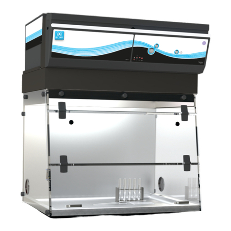
erlab Captair Store Midcap AVPD 804 User manual

Midcap AVPD 804 - AVPS D 804
AVPD 804 - AVPS D 804
AVPD R - AVPS D R
Assembly Instructions
Montage Beschreibung
Notice de Montage
Instrucciones de Montaje
Istruzioni per il Montaggio
1
04/2004
R


Table of contents
Inhaltsverzeichnis
Table de matières
Tabla de contenido
Indice del materiale
Midcap AVPD 804 - AVPS D 804
AVP D 804 - AVPS D 804
AVP D R - AVPS D R
1- Specifications of Store AVPD - AVPS D 804
Store AVPD - AVPS D 804
Store AVPD - AVPS D 804
los armarios AVPD - AVPS D 804
Specificazioni delle Store AVPD - AVPS D 804
Store AVPD R - AVPS D R
Store AVPD R - AVPS D R
Store AVPD R - AVPS D R
los armarios AVPD R - AVPS D R
Specificazioni delle Store AVPD R - AVPS D R
Lock instructions
Türöffnung nach rechts oder links
Serrure ouverture à droite ou à gauche
Cerradura de apertura a la derecha o a la izquierda
page 5
- Kenndaten des Seite 5
- Spécifications des page 5
- Especificaciones pagina 5
- pag. 5
2- Specifications of page 5
- Kenndaten des Seite 5
- Spécifications des page 5
- Especificaciones pagina 5
- pag. 5
3- Assembly instructions page 16
- Montageanleitung Seite 16
- Notice de Montage page 16
- Instrucciones de montaje pagina 16
- Istruzioni per il Montaggio pag. 16
4- page 19
- Seite 19
- page 19
- pagina 20
- Chiusura a destra o a sinistra pag. 20
3
R


Midcap™ AVP D 804 - AVPS D
&
AVPD 804 - AVPS D 804
R
2150 mm 84 2/3”
2420 mm 95 1/4”
505 mm
950 mm
1245 mm
Midcap™ AVP D 804 - AVPS D
&
AVPD 804 - AVPS D 804
R
2150 mm 84 2/3”
2420 mm 95 1/4”
505 mm
950 mm
1245 mm
5
20”
1
09 1997 600009 1997 6000
RR
Midcap™ AVP D 804 - AVPS D
&
AVPD 804 - AVPS D 804
R
2150 mm 84 2/3”
2420 mm 95 1/4”
505 mm
950 mm
1245 mm
5
20”
1
09 1997 600009 1997 6000
RR
Midcap™ AVP D 804 - AVPS D
&
AVPD 804 - AVPS D 804
R
2150 mm 84 2/3”
2420 mm 95 1/4”
505 mm
950 mm
1245 mm
5
20”
1
09 1997 600009 1997 6000
RR
1600 mm 71”

R
2213 mm 87”
R
2213 mm 87”
6
2283 mm
AVPD R - AVPS D R
505 mm
20”
2
R
2213 mm 87”
6
2283 mm
AVPD R - AVPS D R
505 mm
20”
2
R
2213 mm 87”
6
2283 mm
AVPD R - AVPS D R
505 mm
20”
2
R
2213 mm 87”
6
2283 mm
AVPD R - AVPS D R
505 mm
20”
2
RR
950 mm
1245 mm
1600 mm 71”

7
3
Back panel
Panneau arrière
Panel traverso
Panello indietro
Supporting leg
Pied porteur
Apoyo
Piede portante
Base
Plancher
Panel base
Base
Filter housing
Caisson de ventilation
Campana de ventilación
Cassone di ventilazione
Spill tray
Bac de rétention
Bandeja de retenci nó
Vasca di ritenzione
Absorbing material
Tapis absorbant
Afombra absorbente
Tappeto assorbente
Shelf
Étagère
Estanteria
Ripiano
Hinge - Hinge bolt
Charnière - Axe de charnière
Bisagra - Eje de Bisagra
Cerniera - Asse di cerniere
Lockable door
Porte avec serrure et clé
Puerta con cierra
Porta con cerrratura
Filter
Filtre
Filtro
Middle connector
Jonction arrière
Junci n de medio
Congiunzione del centro
ó
Middle panel
Panneau de milieu
Panel de medio
Pannello del centro
Connector piece
Pièce de jonction
Pieza de reuni n
Pezzo de congiunzione
ó
Electrical cord
Cordon électrique
Cord n de alimentaci n
Cordone d’alimentazione
óó
Shelf tapping screw
Vis à tôle
Tornillos de chapa
Vita a lamiera
Stud M5x16 - Washer
Vis à métaux M5x16
Tornillos de metal
Viti a metallo M5x16
Taquet
Taqué
Zeppa
Midcap™ AVP 804
AVP 804
Midcap™ AVPS 804
AVPS 804 AVP R AVPS R
1 1 11
4 4 44
22 22
1 1 11
1 1 11
2 2 44
888
8
66 66
2222
1 - -1
11 11
- - 22
11 11
1 1 11
46 46 4646
4 4 4
4
50 50 6465
Materials list
Liste du matériel
Listino del materiale

Mettreunmoyendeprotectionsuffisammentgrandsurlesolpourrecevoirl'armoires.
Poser sur celui-ci une base C, l'ouverture du bac de rétention Fau-dessus, les ouïes
perforéesverslehaut. FixerunpiedporteurBàlabaseC(Fig.1)àl'aidede4visàtôle
S,d'une cléemmanchée en tube N°7oumieux d'untournevis électrique équipéd'une
douille N°7 (fig.2). Fixer de la même manière le deuxième pied porteur B’ de
l’autre côté de la base C(fig3).
C
8
3.1
Legen Sie auf die Erde einen Schutz, der breit genug ist, um darauf 2 Schränke
nebeneinander zu stellen. Darauf legen Sie flach ein Boden C, mit der Öffnung des
Auffangbeckens Fund der perforierten Fläche nach oben zeigend. befestigen Sie
einen Seitenwand Bam Boden C(Bild 1) mit Hilfe von 4 Schrauben Sund eines
Schraubenschlüssels N°7 oder noch besser mit Hilfe eines Schraubenziehers mit
Schlüsselgroße N°7 (Bild 2). Befestigen Sie auf der selben Art den zweiten Seitenwand
B’ an der anderen Seite des Bodens C(Bild 3).
Cover the floor with enough lining to protect the storage cabinet. Place base Con the
lined floor with retaining tray opening and air inlets on top. Attach the supporting leg
BtothebaseCusingthe4sheetmetalscrewsprovidedandacordlessscrewdriverwith
No. 7 socket (fig.2). Attach second supporting leg B’ to the other side of base Cin
the same manner (fig.3).
F
GB
D
B’ B
BB
C
RR<
>=
SP Dejar una tela de protección suficientemente grande sobre el sol para recibir los dos
armarios al lado uno de otro. Colocar un panel de base Csobre él, la apertura de la
bandejaderetenciónFpor encima,lasbocasdeventilaciónenlaparte superior.Fija
unapoyoBalpaneldebaseC(ver figura1).Conlaayudade4tornillosdechapaS,
deunallaveenmangadaentuvonº7omejordeundestornilladoreléctricoequipado
de un tornillo nº7 (ver figura 2). Colocar de la misma manera el segundo
apoyo B’ del otro lado del panel de base C(ver figura 3).
Mettere una protezione sufficientemente grande per potere posare due armadi
affiancati. Posare su questo una base C, l'apertura della vasca di ritenzione F al
disopra, le feritoie perforate verso l' alto. Fissare un piede portanteBalla base C(fig
1) con l'aiuto di 4 viti a lamiera S, con una chiave immanicata in tubo n°7 o con un
cacciavite equipaggiato di un bossolo n°7 (fig 2 ). Fissare della stessa maniera
secondo piede portante B’ del altro lato della base C(fig 3 ).
I
F
S
F

Assembler la deuxième armoire de la même façon juste à côté de la première.
Emboiter la pièce de jonction Qaux deux pieds porteurs centraux puis la fixer à
l'aide de 4 vis à tôle S . (Fig. 5)
9
3.2
Setzen Sie den zweiten Schrank auf der selben Art ganz neben dem ertsen zusammen.
Stecken Sie das VerbindungsteilQauf den beiden zentralen Füßen der Seitenwände
Auf und dann befestigen Sie es mit Hilfe von 4 Schrauben S .
Assemblethesecondstoragecabinetinthesamemannernexttothefirstone.Slidethe
connector piece Qover the two center supporting legs and attach it wth the 4 sheet
Metal screws S provided (fig.5).
F
GB
D
RR
SP Juntarelsegundoarmariodelamismamaneraalladodelaprimera.Encajarlapieza
de reunión Qa los pies de los apoyos central después colocarla con 4 tornillos de
Chapa S . (ver figura 5).
Assemblare della stessa maniera il secondo armadio giusto al lato del primo.
Incastrare il pezzo di congiunzione Qai due piedi portante centrali ; poi fissarla con
L'aiuto di 4 viti a lamiera S . (fig 5)
I
B
Q
C
C’
B’
?@
S

10
3.3
F
GB
DFür die folgende Aktion sind zwei Personen notwendig. Zusammengeschraubten
Doppeltschrank aufstellen, am besten mit dem Rücken zur Wand, wo er seinen Platz finden soll (Bild 7).
Lassen Sie genug Platz hinter dem Schrank, um die folgenden Aktionen
durchzuführen:
StellenSieundbefestigenSieeineRückwandAoderA'zwischendenbeidenSeitenwändenB-B1oderB'-
B1' mit Hilfe von acht Schrauben S. Machen Sie auch so für den zweiten Schrank
(Bild 8)..
Deux personnes sont nécessaires pour cette opération. Mettre debout l' armoire double ainsi
assemblée, de préférence le dos de l'armoire face au mur où elle devra être placée (fig.7) tout en
laissant assez de place derrière pour effectuer les opérations suivantes:
Placer et fixer un panneau arrière A ouA' entre les deux pieds porteurs B - B1 ou B'- B'1 à l'aide de
huit vis à tôle S . Répéter l'opération pour l'autre armoire.(fig.8)
Placer la jonction M sur lesdeux pieds porteurs centraux B et B et la fixer'à l'aide de deux vis à tôle
S aux deux panneaux arrières a - a'. (fig. 8)
Two people are needed for this operation. Move the two cabinets upright against the wall where they
will be placed (fig.6) while leaving enough space to perform the next operations:
Place and attach a rear panel Aor A' between the two supporting legs B B1 or B' B'1 with 8
sheet metal screws Sprovided. Repeat for the other storage cabinet (fig.7).
Place junction M over the two center supporting legs Band B’ and attach it to the two rear
panels Aand A' with two sheet metal screws Sprovided (fig.7).
SP Dos persones sean necesarias para hacer esta manipulación. Levantar el armario doble, de
preferencia el panel trasero del armario colocado a la pared a donde se instalará.(ver figura 7)
dejando un espacio detrás del armario para hacer las manipulaciones siguientes :
Colocar y fijar el panel trasero A o A' entre los dos apoyos B B1 o B' B'1 con 8 tornillos de
autoscado S. Volver la manipulación para el otro armario. (ver figura 8).
Colocar la pieza de reunión M sobre los dos apoyos centrales B y B' y fijarla con 2 tornillo de
chapa S al panel trasero A A'. (ver figura 8).
Due persone sono necessarie per questa operazione. Mettere in piedi l'armadio doppio cosi
assemblato, di preferenza il tergo del'armadio in faccia al muro dove sarà messa per effettuare le
seguenti operazioni : Mettere e fissare un pannello indietro A o A' tra i due piedi portanti B - B1 o
B' - B'1 con l'aiuto di otto viti a lamiera S. Ripetere l'operazione per l'altro armadio (fig 8).
Mettere la congiunzione M sui i piedi portanti centrali B e B1 e fissarla con l'aiuto di due viti a
lamiera S ai due pannelli indietro A A'. (fig 8)
I
B
B’
A
C
RR
A
B
C’
A’
M

11
3.4
F
GB
DlenSiedieZwischenwändePindiePositionsschiltzeinderMittederBodenCundindie
entsprechenden Öffnungen in der Mitte der Rückwände A.
Placer et Cliper le panneau de milieu Pdans les fentes de positionnement au centre
des plancher Cet dans les ouvertures correspondantes au centre des panneaux
arrières A.
Placeand clip themiddle panel Pin the positioningslots at the center offloor C and in
the coresponding openings in the middle of the rear panels A.
SP Encajar los paneles del medio Pdentro de las abertura de posicionamiento al central
de los pisos Cy dentro de las aberturas correspondiente al centro de los paneles
traseros A.
Mettere e clipper i pannelli di centro Pnelle fessure di posizionamento al centro dei
pavimenti Ce nelle aperture corrispondenti al centro dei pannelli indietro A.
I
A
P
B1
B
C
RR
C
a
C
CStore Midcap™ AVP D 804 - AVP D 804 - AVP D R
a
CStore Midcap™ AVPS D 804 - AVPS D 804 - AVPS D R
B’
P’
C’
B’1
A
A’

F
GB
DLegen Sie das Decken des Doppeltschrankes N(Bild 9).
Befestigen Sie den zentralen Teil des Deckens Nan den beiden zentralen Seitenwänden Bmit Hilfe
von 4 Schrauben M5x16 und von Scheiben (Bild 9a).
Befestigen Sie das Decken Nan den beiden Außenseitenwänden B1 - B’1 vorne und hinten mit
Hilfe der 4 mitgelieferten Schrauben M5x16 und Scheiben (Bild 9b).
Poser le plafond de l'armoire double N. (fig. 9)
Fixer la partie centrale du plafond Naux deux pieds porteurs centraux B - B' à l'aide de 4 vis à
métaux M5x 16 et rondelles. (fig. 9a)
Fixer le plafond N aux deux pieds porteurs extérieurs B1 - B’1 à l'avant et à l'arrière à l'aide de 4
vis M5x16 et rondelles. (Fig.9b)
Place the ceiling of the double Captair store N. (fig. 9)
Attach the center of the ceiling N to the middle supporting legs B - B' with the 4 M5 x 16 sheet metal
screws and washers provided. (fig.9a)
Attach the ceiling Nto the two outside supporting legs B1 - B’1 at the front and at the rear using the 4
screws M5 x 16 and washers provided. (fig. 9b)
SP Poner el techo del armario doble N.
Colocar la parte central del techo Na los apoyos centrales B - B' con 4 tornillos de metal M 5X
16 y discos. (ver figura 9a).
Colocar el techo N a los apoyos exteriores B1 - B’1 en la parte frontal y trasera con 4 tornillos M
5X 16 y discos. (ver figura 9b).
Posare il soffitto dell'armadio doppio N. (fig 9).
Fissare la parte centrale del soffitto Nai due piedi portanti centrali B - B' con l'aiuto di 4 viti a
metallo M5x 16 e rondelle. (fig.9a)
Fissare el soffitto Nai due piedi portanti centrali B1 - B’1 con l'aiuto di 4 viti a
metallo M5x 16 e rondelle. (Fig.9b)
I
3.5
RR
12
D
DaDb
N
B’1 BB1
A
A’
N
B’
B
B’ B’1
N

RR
F
GB
D
PoserlecaissondeventilationDversl'avantduplafondNauniveaudel'ouverture.Glisserlecaissonde
Ventilation Dvers l'arrière sur le plafond Nafin de le clippé. (Fig. 10 - 10a)
Ouvrir le caisson de ventilation en le levant à fond les compas rouges le maintiendront ouvert.
Fixer ensuite le caisson de ventilationDà l'avant du plafond Nà l'aide des 2 vis à métaux M 5x16 et
Des 2 rondelles (fig. 10b).
Place the ventilation housing Dat the front of the ceiling N over the opening in the ceiling. Slide the
ventilation housing Dtowards the rear of the ceiling Nin order to clip it (fig. 10 - 10a).
Open the ventilation housing, the red swivel arm will keep it open.
ThenfixtheventilationhousingDatthefrontoftheceilingNusingthe2sheetmetalscrewsM5x16and
the 2 washers provided (fig. 10b).
SP Colocar la campana de ventilación Dhacia el frente del techo en la apertura. Deslizar el cajón de
ventilación hacia la parte sobre el límite máximo con el fin de encajarlo. (ver figura 10 - 10a)
Abrir la campana de ventilación al aumentarlo con profundidad los compases rojos los mantendrán
abierto.
Fijar a continuación le campana de ventilación delante del techo con ayuda de los 2 tornillos en metal
M 5x16 y de los 2 discos. (ver figura 10b)
I
RR
<;
D
<;
B’
D
B
Store Midcap™ AVPD 804 - AVPD 804 - Midcap™ AVPS D804 - AVPS D 804
3.6
Posare il cassone di ventilazione Dverso l'avanti del soffitto Nal livello dell'apertura. Scivolare il
cassone di ventilazione Dverso l'indietro sul soffitto Na fin de clipperlo (fig 10 - 10a) .
Aprire il cassone di ventilazione rialzandolo al massimo, i compassi rossi lo mantenerenno aperto.
Fissare in seguito il cassone di ventilazione Da l'avanti del soffitto Ncon l'aiuto di due viti a metallo
M5x16 e due rondelle. (Fig 10b)
SetzenSie den VentilationsaufsatzDoben auf, in der Richtung der Vorderseite des DeckensN,auf dem
Niveau von der Öffnung. Rutschen Sie den Aufsatz nach hinten auf dem Decken, um ihn
einzufügen (Bild 10 - 10a).
Öffnen Sie den Aufsatz Dmit Hilfe der roten Kalterungen.
Befestigen Sie dann den Ventilationsaufsatz Dauf die Vorderseite des Deckens Nmit Hilfe der 2
Schrauben und der 2 Unterlegscheiben (Bild 10b).
<;a
<;b
D
N
N
D
13

14
3.7
RR
F
D
Poser le caisson de ventilation Dvers l'avant du plafond N au niveau de l'ouverture.
Glisser le caisson de ventilation Dvers l'arrière sur le plafond N afin de le clippé. (fig. 11
- 11a)
Fixer ensuite le caisson de ventilation Dà l'avant du plafond N à l'aide des 2 vis à
métaux M 5x16 et des 2 rondelles (fig. 11b).
Place the ventilation housing Dat the front of the ceiling Nover the opening in the ceiling.
Slide the ventilation housing Dtowards the rear of the ceiling Nin order to clip it (Fig. 11 -
11a).
Then fix the ventilation housing Dto the front of the ceiling Nusing the 2 sheet metal
screws M5 x 16 and the 2 washers provided (Fig. 11b).
SP Colocar la campana de ventilación Dhacia el frente del techo en la apertura. Deslizar el
cajón de ventilación hacia la parte sobre el límite máximo con el fin de encajarlo. (ver
figura 10 -10a).
Fijar a continuación le campana de ventilación delante del techo con ayuda de los 2
tornillos en metal M 5x16 y de los 2 discos.(ver figura 11b)
Posare il cassone di ventilazione Dverso l'avanti del soffitto Nal livello dell'apertura.
Scivolare il cassone di ventilazione Dverso l'indietro sul soffitto a fin de clipperlo. (fig 11
11a).
Fissare in seguito il cassone di ventilazione Dnel avanti del soffitto Ncon l'aiuto di due
viti a metallo M5x16 e due rondelle. (Fig 11b)
I
Store AVPD R - AVPSD R
GB
Setzen Sie den Ventilationsaufsatz Doben auf, in der Richtung der Vorderseite des Deckens
N, auf dem Niveau der Öffnung. Rutschen Sie den VentilationsaufsatzDnach hinten auf
dem Decken, um ihn einzufügen (Bild 11 -11a).
Befestigen Sie dann den Ventilationsaufsatz Dauf die Vorderseite des Deckens Nmit Hilfe
der 2 Schrauben M5x16 und von 2 Unterlegscheiben (Bild 11b).
<b
<
D
<a
<
B’
D
B
N
<<
N
D

15
3.8
RR
Store Midcap™ AVPD 804 - AVPD 804 - Midcap™ AVPSD 804 - AVPSD 804
F
GB
D
SortirlefiltreLdesonemballage,retirerl'enveloppeplastique,puisleglisseràfonddu
cadre butée filtre en s'assurant du bon positionnement des lettres d'identification (vers
l'avant gauche de l'armoire).
Relever au maximum le caisson de ventilation Det le laisser descendre en le
maintenant afin de le refermer.
Ces opérations sont également valables lors du changement de filtre (voir la notice technique).
Take the filter Lout of its packing and plastic bag and slide it fully inward in the
ventilation housing. The identification letters must show on the left front side of the
cabinet.
To close the ventilation housing D, fully open it at first and then hold it while it goes
down,until it is closed.
This operation is the same when you replace a filter (see technical instructions).
SP Sacar el filtro L de su bolsa de plástico y deslizarlo hacia adentro. La letra de
identificación debe aparecer en la parte frontal izquierda del armario. Destacar como
máximo la campana de ventilación D y dejarlo descender manteniéndole con el fin de
volverloacerrar.
Esta operación es la misma que cuando se coloca un filtro nuevo (ver Instrucciones técnicas).
Tirar fuori il filtro L dal'imballaggio, sfilare la busta di plastica, poi scivolarle al
massimo nel ricetta colo, assicurandosi della buona posizione delle lettere
d'identificazione(versol'avantisinistrodell'armadio).Rialzarealmassimoilcassonedi
ventilazioneDelasciarloscenderemantenendoloafinde chiuderlo.
Queste operazioni sono ugualmente validi anche quando si cambia il filtro.
(vedere la notizia tecnica).
I
Nehmen Sie den Filter aus der Verpackung und Plastikhülle und schieben Sie ihn ganz
nach hinten ein. Vergewissern Sie sich, daß die Beschriftung stimmt (vorne links im
Schrank). Erhöhen Sie höchstmöglich den Ventilationsaufsatz Dund lassen Sie ihn
niedergehen, indem Sie ihn halten, um ihn zu schließen.
Dasgleiche gilt bei Filterwechsel (siehe Bedienungsanleitung).
RR
D
L
<=

16
3.9
F
GB
DSchieben Sie das Auffangbecken Fauf den 2 Schienen unter den Boden C.
Legen Sie nun die mitgelieferte Adsorbtionsmasse Gin das Auffangbecken Fein (Bild
14).
Legen Sie nun die mitgelieferte Adsorbtionsmasse Gund G’ in das Auffangbecken
Fein (Bild 15).
Placer le bac de rétention Fsous le plancher C en le glissant sur les 2 cornières
du plancher C.
Placer le tapis absorbant fourni Gà l'intérieur du bac de rétention F. (fig. 14)
Placer les tapis absorbant fournis G et G’ à l'intérieur du bac de rétention F. (fig.
15)
Place the spill tray Funder the base panel Cby sliding it on the 2 sliding tracks.
Place the absorbing material Gin the spill tray F. (fig. 14)
Place the absorbing material G and G’ in the spill tray F. (fig. 15)
SP Ccolocar la bandeja deretención Fdebajo del panel base Cdestizándolasobre las2
guias deslizantes.
Colocar le material absorbente Gen la bandeja de retención F. (Ver figuras 14)
Colocar los materiales absorbentes Gy G’ en la bandeja de retención F. (Ver figuras
15)
Mettere la vasca di ritenzione Fsotto il pavimento C facendolo scivolare sulle 2
angolaridelpavimentoC.
MettereiltappetoabsorbentefornitoGalinternodellavascadiritenzioneF.(Fig14)
Mettere le tappeti absorbente forniti Ge G’ al interno della vasca di ritenzione F. (Fig
15)
I
RR
<> <?
F
BB’ B
F
B’ GG
G’
<? Store Midcap™ AVPD 804 - AVPD 804 - AVPD R
<@ Store Midcap™ AVPSD 804 - AVPSD 804 - AVPSD R
CC

17
3.10
F
GB
DStellen Sie 6 Zapfen Tpro Regal auf die von Ihnen gewünschte Höhe in die
entsprechenden Schlitze : einen Zapfen pro Seitenwand Bund B’, 4 Zapfen auf die
Rückwand A. Stellen Sie dann das Regal auf die 6 so gestellten Zapfen. Wiederholen
Sie dieAktion für die anderen Regale.
Placer 6 taquets Tpar étagères à la hauteur souhaitée dans les fentes prévues à cet
effet. Un taquet par pied porteur B et B’ , 4 taquets sur le panneau arrière A. Puis
placer l'étagère sur l'ensemble des 6 taquets ainsi positionnés. Répéter l'opération
pour les autres étagères.
Use 6 clips T per shelf and place them at the desired level in the matching slots in the
cabinet. Use 1 per supporting leg, 4 on the rear panel A. Fit the shelf on the 6 clips.
Repeat the operation for the other shelves.
SP Colocar 6 bloques T por estanterías a la altura deseada en las rajas previstas en este
efecto. Un bloque por apoyo B yB’, 4 bloques sobre el panel posterior A. Luego
colocar la estantería sobre el conjunto de los 6 bloques así colocados. Repetir la
operaciónParalasotrasestanterías.
Mettere 6 zeppe Tper ripiano all'altezza desiderata nelle fessure previste a questo
effetto. Una zeppa per piede portante Be B’, 4 zeppe sul pannello indietro A. Dopo,
mettere il ripiano sul'insieme dei 6 zeppe cosi posizionate. Ricominciare l'operazione
perialtriripiani.
I
RR
<A Store Midcap™ AVPD 804 - AVPD 804 - AVPD R
B’ A
HB
<=>?@
T
<@

18
3.11
RR
<B Store Midcap™ AVPSD 804 - AVPSD 804 - AVPSD R
<A
B’ A
HB
<=>?@
T
P
H
F
GB
DStellen Sie 6 Zapfen Tpro Regal auf die von Ihnen gewünschte Höhe in die
entsprechenden Schlitze : einen Zapfen pro Seitenwand Bund B’, 4 Zapfen auf die
Rückwand A. Stellen Sie dann das Regal auf die 6 so gestellten Zapfen. Wiederholen
Sie dieAktion für die anderen Regale.
Placer 6 taquets Tpar étagères à la hauteur souhaitée dans les fentes prévues à cet
effet.Untaquetparpied porteur B etB’ , 4 taquetssur lepanneau arrière A, milieuP.
Puisplacerl'étagèresurl'ensembledes6taquetsainsipositionnés.Répéterl'opération
pour les autres étagères.
Use 6 clips T per shelf and place them at the desired level in the matching slots in the
cabinet. Use1persupportingleg,4ontherearpanelA,middleP . Fittheshelfonthe
6 clips.
Repeat the operation for the other shelves.
SP Colocar 6 bloques T por estanterías a la altura deseada en las rajas previstas en este
efecto. Un bloque por apoyo B yB’, 4 bloques sobre el panel posterior A, medio P.
Luego colocar la estantería sobre el conjunto de los 6 bloques así colocados. Repetir
laoperaciónParalasotrasestanterías.
Mettere 6 zeppe Tper ripiano all'altezza desiderata nelle fessure previste a questo
effetto. Una zeppa per piede portante Be B’, 4 zeppe sul pannello indietro A,centro
P. Dopo, mettere il ripiano sul'insieme dei 6 zeppe cosi posizionate. Ricominciare
l'operazioneperialtriripiani.
I

19
3.12
F
GB
DBefestigen Sie ohne anzuziehen - das Scharnier Imit Hilfe der 3 Schrauben auf einer
der Seitenwände Bnach der gewählten Türöffnung J.WiederholenSie diesesmit dem
unteren Scharnier (nur eine Schraube für das mittlere Scharnier) (Bild 18).
Setzen Sie die 3 vormontierten Scharniere auf der Tür Jmit denen, die Sie auf der
Seitenwand Bmontiert haben mit den 3 Mittelstücken zusammen I’ (Bild19). Ziehen
Sie die Schrauben der auf der Seitenwand montierten Scharniere an.
Fixer sans serrer la charnière Ià l'aide de 3 vis tôle sur un des pieds porteurs Ben
fonction du sensd'ouverture choisi de la porte J.Répéter l'opération pourla charnière
dubas(uneseulevispourlacharnièredumilieu).(Fig18)
Assembler les 3 charnières prémontées sur la porte Jà celles que vous avez fixées sur
le pied porteur Bà l'aide des 3 axes I’ de charnière inclus (fig. 19). Serrer les vis des
charnières montées sur le pied porteur.
Fix the hinge Iwith 3 self tapping screws on one of the supporting legs B, the right
or the left one, depending on the opening side of the door J. Repeat the same
operation with the 2 other hinges (a single screw for the middle hinge). (fig. 16)
Assemble the 3 hinges that are already mounted on the door Jto those you have
fixed on the supporting leg Bwith the 3 hinge bolts (fig. 17). …Tighten the screws
of the hinges mounted on the supporting leg.
SP Fijarsinapretarlabisagralconayudade3tornilloschapasobreunodelosapoyosen
función del sentido de apertura elegido de la puerta J. Repetir el operador para la
bisagra e la parte baja (un único tornillo para la bisagra del medio).
Juntarlas3bisagrasprefabricadassobreelapoyoBconayudadelos3pasadoresde
charnela I’incluidos. Apretar los tornillos de las bisagras subidas sobre el apoyo.
Fissare senza serrare la cerniera Icon l'aiuto di 3 viti a lamiera su uno dei piedi
portanti Binfunzione del senso dell'apertura scelta della porta J. Ricominciare
l'operazioneperlacernieradelbasso(unasolaviteperlacernieradelcentro)(fig18).
Assemblarele 3 cerniere premontate sulla portaJ aquelle cheavete fissatosul piede
portante Bcon l'aiuto di 3 assi di cerniera inclusi (fig 19). Serrare i viti delle cerniere
montate sul piede portante.
I
RR
<B <C
B’
I
J
B’
I
I’
S

20
3.13
F
GB
DSchreibenSiedieNummerdesSchlüsselsindemoberenKästchen.
UmdieTüröffnungzuändern,nehmenSiedieDruckschraubeausdemErlaßkamholz.
Nehmen Sie den Erlaßkamholz heraus und überprüfen Sie die Position des
Erlaßkamholzs 90°. Stellen Sie den Erlaßkamholz 90°auf die Position 1 bei einer
Öffnung nach rechts oder auf die Position 2 bei einer Öffnung nach links. Platzieren
Sie den Erlaßkamholz wieder undBesfestigen Sie das Gesamt mit der Druckschraube(
Bild21).
Releverlenumérodelacléetnoterledanslacaseci-dessus.
Pour modifier le sens d'ouverture de la porte. Enlever la vis de serrage de la Cam.
RetirerlaCametvérifierlapositiondelaCamd'arrêt90°.PlacerlaCamd'arrêtdansla
position 1 pour une ouverture à droite ou dans la position 2 pour un ouverture à
gauche.ReplacerlaCametfixerl'ensembleaveclavisdeserrage.(Fig.21)
Check the key number and write it down in the square above.
To change the opening side of the door: remove the tightening screw of the Cam.
Removethe Camand check thepositioning ofthe90° Camstop. Place theCamstop
inposition1foranopeningtotherightorinposition2foranopeningtotheleft.Place
back the Cam and ure with the tightening screw (fig.21).
SP Destacar el numero de la llave y escribirlo en la casilla si arriba.
Para modificar el sentido de apertura de la puerta. Retirar el tornillo de la Cam. y
comprobar la posición de la Cam. de paro 90º. Colocar la Cam. de paro en la
posición 1 para una apertura a la derecha o en la posición 2 para una apertura a la
Izquierda. Poner de nuevo la Cam. y fijar el conjunto con el tornillo.
Notare il numero della chiave e notarlo nella casella qui sopra.
Per modificare il senso d'apertura della porta. Levare la vite di serraggio della cam.
Levare la cam e verificare la posizione della cam di fermata 90°. Mettere la cam di
fermata nella posizione 1 per una apertura a destra o nella posizione 2 per una
aperturaa sinistra.Rimetterela camefissare l'insiemeconla vitediserraggio. (fig19)
I
RR
<D
Key number
Nummer des Schlüssels
Numéro de la clé
Numero de la llave
numero della chiave
This manual suits for next models
5
Other erlab Laboratory Equipment manuals
