Charging the Battery/Palm and Top Straps
4
Charging the Nickel Metal Hydride Battery
Before using a battery for the first time, be
sure to charge and drain the battery at least
three times. This will enable the battery to
achieve maximum life.
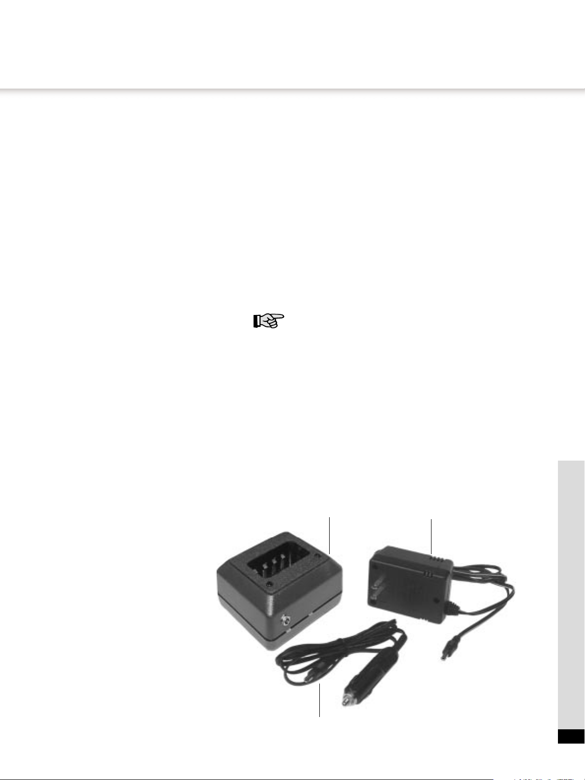
Using the Battery Charger
The battery should be charged in the battery charger,
using either the AC or DC adapter provided (Figure 2).
To charge battery, simply insert battery into charger so
that the metal connectors on the battery are aligned
with the metal connectors in the charger. A red light will
illuminate on the charger to indicate that the battery is
charging. When the light on the charger turns to green
your battery will be fully charged. You may leave the
battery in the charger indefinitely. You cannot
overcharge the battery.
Using the Direct Charge System
The direct charge system will allow the battery of the
Bullard Thermal Imager to be charged inside the
camera. The standard battery charger should be
connected to a power supply using either the AC or DC
adapter provided. Connect the charger to the camera by
using the gray connector cord provided. Insert one end
of the cord into the charger using the outlet provided on
the front of the charger and the other end into the direct
charge plug located on the handle of the thermal imager.
A red light will illuminate on the charger to indicate that
the battery is charging. When the light on the charger
turns to green your battery will be fully charged. You
may leave the direct charge system in place indefinitely.
You cannot overcharge the battery.
Using the Direct Charge System/Battery
Charger
A battery can be charged in the charger at the same
time as the battery in the camera is being charged by
using the directions previously mentioned. Charging
both batteries at the same time will not lengthen the
charge time or cause any damage to the batteries or
charging unit.
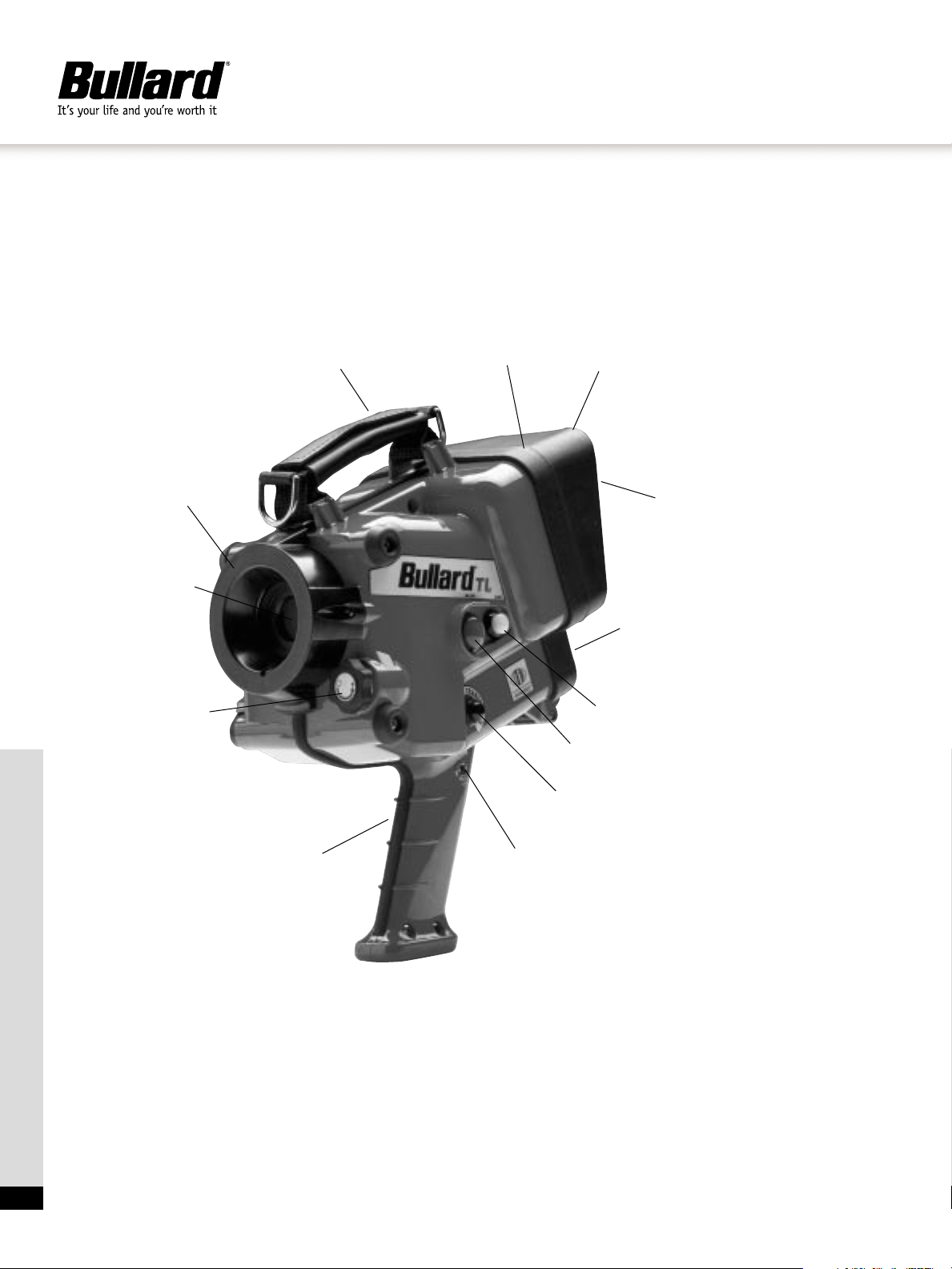
Loading the Battery
To open the battery compartment (Item 4, Figure 1),
turn the two thumb knobs outward and pull the door
open. Remove battery. Now insert a fully charged
battery making sure the Bullard decal is facing away
from the camera and the type is right side up. If the
battery has not been inserted correctly the door will not
shut and the thumb knobs can not be secured. If the
door will not shut please remove the battery and review
the instructions above. The battery can easily be
replaced in the dark.To do so, simply locate the notched
bottom of the battery. Make sure the notch is pointing
away from you and is on the left-hand side. If the door
will not shut please remove the battery and try again.
Additionally, as with all batteries, your Bullard
rechargeable battery will experience a slow drain of its
charge during storage. The amount of drain varies
widely based on storage conditions. For best
performance, charge each of your batteries every two
weeks.
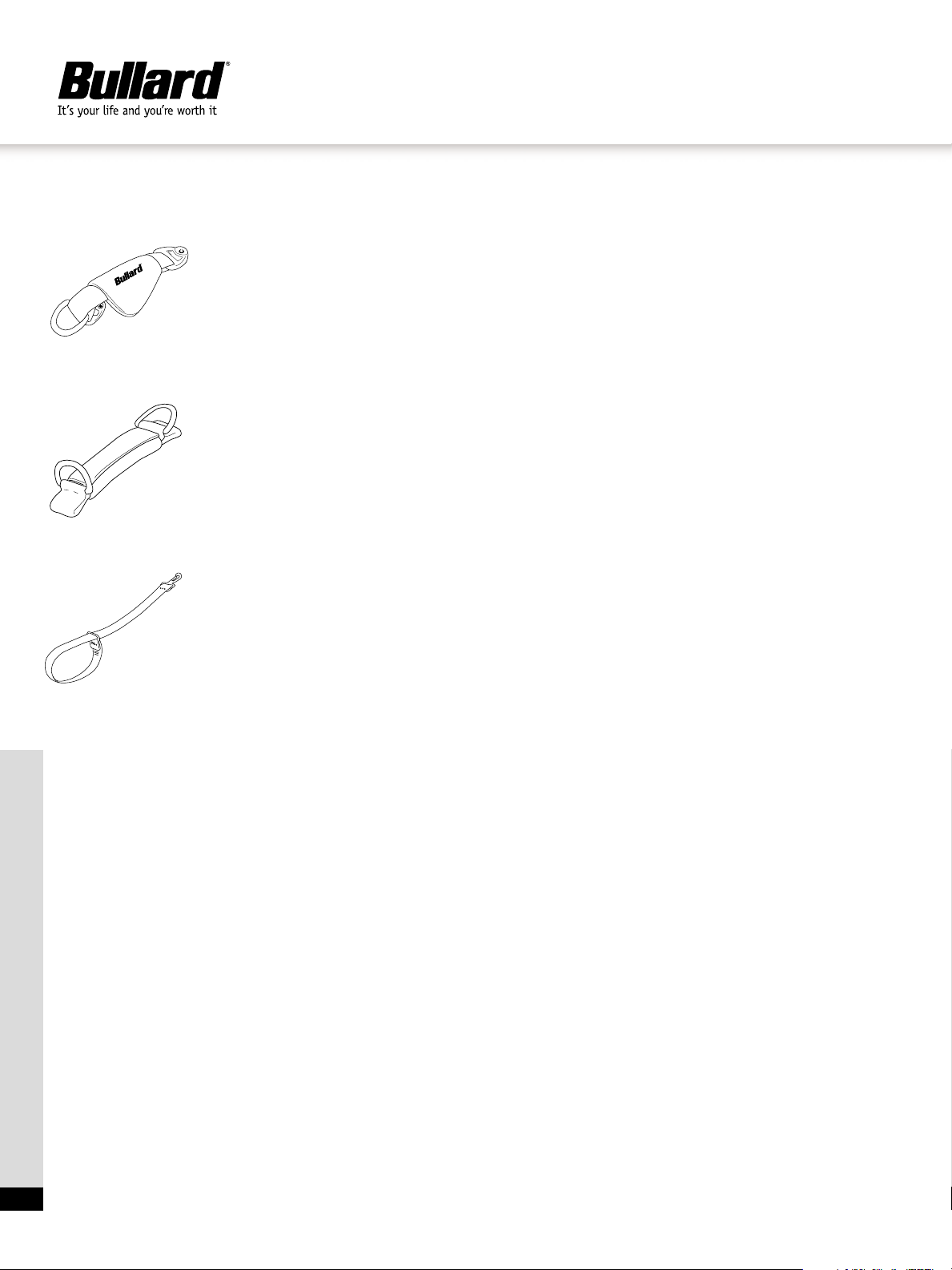
Palm and Top Straps
The palm and top straps are designed to allow the user
to field replace the top and side strap without having to
return the imager to the factory.
Replacing the Palm Strap
Using a 3/8" wrench, remove the nut on the right side of
the strap. Remove the strap from the screw by lifting
away from the camera. Remove the left side of the strap
by removing the screw with a Phillips screwdriver. The
new strap should be attached by first securing the left
bracket to the camera using the existing screw.The right
bracket should then be secured by placing the bracket
on the screw and tightening the nut. The strap is
correctly attached when the Bullard logo is facing
outward.
Adjusting the Palm Strap
To adjust the palm strap on the side of the unit, pull open
the leather hand guard and readjust the strap. Once
adjusted to comfortable length, close the leather hand
guard.
Adjusting the Shoulder Strap
To attach the shoulder strap, clip the hooks to any of the
three D-rings on the unit. Adjust the strap to a
comfortable length.
Replacing the Top Strap
Unwrap leather pad from strap to expose the ends of
the strap. Remove right side of strap from Velcro®, wrap
the end around the anchor on the top of the camera and
re-attach to the Velcro. Remove the left side of the strap
from the Velcro, wrap the end around the anchor on the
top of the camera and re-attach to the Velcro. Wrap
leather pad around the strap ends.
Wrist Strap
This strap can be used as a backup to keep the imager
from falling if it should slip from your hand. The
adjustable strap fits over the sleeve of your turnout
gear and can adjust to any size wrist. The wrist strap
can be easily attached to any D-ring located on the
camera.
Top Strap
Palm Strap
Wrist Strap