Single Channel Wireless Air Spring Controls L6557
3
KIT DIAGRAM: 10470
Please make sure all the items shown in the kit contents on Page 2 are provided in your kit before starting the installation.
UNAUTHORIZED DISCLOSURE, USE OR MANUFACTURE IN WHOLE OR IN PART IS PROHIBITED ELECTRONIC
DESIGN AND OTHER DISCLOSURES PROPERTY OF PACBRAKE CO. SURREY,
UNLESS OTHERWI SE SPECIFIED:
UPDA TED CONTROLLER PA RT NUMBER
ASSEMBLY, 325 SERIES SINGLE CHANNEL WIRELESS
D.M.Y. 12.10.2021 ENG: Snider B.
MOUNT AIR INLET FILTER IN CLEAN AND
DRY AREA WHERE IT IS PROTECTED
FROM ROAD SPRAY AND DEBRIS
HP10451 ASSEMBLY, 325 WIRELESS COMPRESSOR 1
HP10454 HARNESS, SINGLE CHANNEL WIRELESS 1
C20648 CONTROLLER, WIRELESS AIR CONTROLS 1
P60100 SCREW, #10 x 3/4" SELF TAPPING 1
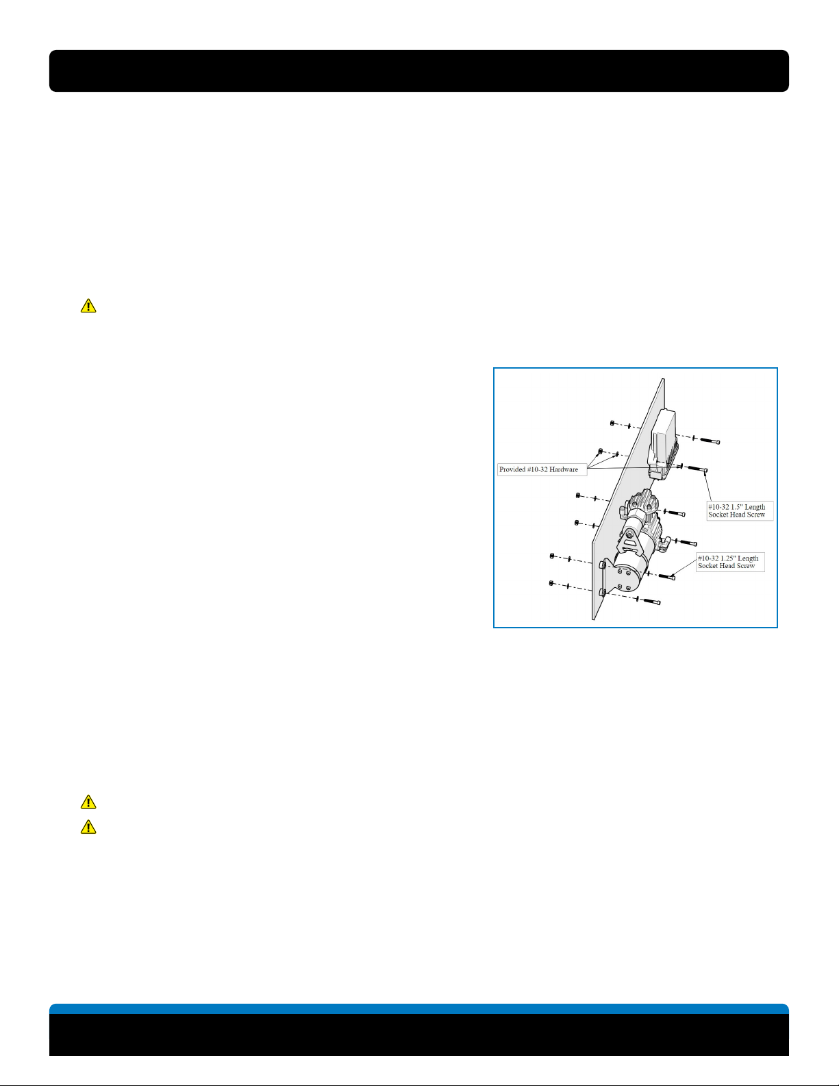
C10848 SCREW, #10-32 x 1.25" SOCKET HEAD 4
HP1521 SCREW, #10-32 x 1.5" SOCKET HEAD 2
C10406 WASHER, #10 FLAT 12
C10843 NUT, #10-32 NYLON LOCK 6
HP1176 FITTING, TEE, 1/4" OD TUBE 1
M8280 NYLON TUBE, 1/4" OD, BLACK
M8685 NYLON TUBE, 1/4" OD, BLUE
M6083 FUSE HOLDER, 15 AMP MAX 1
M8170 FUSE HOLDER, 30 AMP MAX 1
M8115 TERMINAL, BLADE, 14-16 AWG 1
M8262 TERMINAL, RING, 3/8", 10-12 AWG 2
M8159 CONNECTOR, BUTT, 10-12 AWG 1
M8028 CONNECTOR, BUTT, 14-16 AWG 1
COMPRESSOR ASSEMBLY AND CONTROLLER MUST BE
24"] OF EACH OTHER DUE TO
IF REQUIRED, HARNESS CAN BE EXTENDED. ENSURE TO USE
MATCHING WIRE TYPE, WIRE SIZE AND SEALED CONNECTIONS
SELF TAPPING SCREW OR TIE
CUT HARNESS TO REQUIRED LENGTH FOR
33% @ 689.5 kPa [100 psi]
MAXIMUM CONTINUOUS RUN TIME
20 Minutes ON / 40 Minutes OFF
AMBI ENT TEMPERATURE RANGE
-40°C to +70°C [-40°F TO +158°F]
I P5 4 Compres s or As s embl y
PERFORMANCE CHARACTERISTICS
ALL CONNECTORS MUST BE FULLY SECURED AND LATCHED
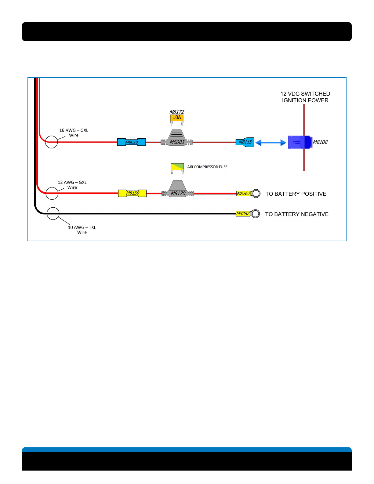
12 VDC SWITCHED IGNITION POWER T-TAP CAN BE CRIMPED TO A CONSTANT 12 VDC POWER SOURCE, GIVING USER THE ABILITY TO CONTROL SYSTEM WHILE
VEHICLE IS OFF. CONTROLLER CONSUMES APPROXIMATELY 35-80 mA IN STANDBY MODE, WHICH WILL SLOWLY DISCHARGE THE BATTERY
REMOVE PINS FROM HARNESS CONNECTORS TO PASS HARNESS THROUGH SMALL SIZED HOLES
MOUNT COMPRESSOR ASSEMBLY OR CONTROLLER DIRECTLY ON ENGINE OR OTHER COMPONENTS EXHIBITING HARSH VIBRATION
MOUNT COMPRESSOR ASSEMBLY OR CONTROLLER IN AREAS WITH AMBIENT TEMPERATURES ABOVE 70°C [158°F]
MOUNT CONTROLLER IN ENCLOSED METAL AREA TO ENSURE BLUETOOTH SIGNAL CAN CONNECT WITH MOBILE DEVICE
IF EXTENDING WIRE LENGTHS, INDIVIDUAL RUNS MUST NOT EXTEND BEYOND 10 METERS [30 FEET] FROM CONTROLLER
ASSEMBLY IS CONTROLLED VIA BLUETOOTH CONNECTION WITH MOBILE DEVICE AND PACBRAKE’S WIRELESS AIR SPRING CONTROLS APP
UNAUTHORIZED DISCLOSURE, USE OR MANUFACTURE IN WHOLE OR IN PART IS PROHIBITED ELECTRONIC
DESIGN AND OTHER DISCLOSURES PROPERTY OF PACBRAKE CO. SURREY,
UNLESS OTHERWISE SPECIFIED:
UPDATED CONTROLL ER PART NUM BER
ASSEMBLY, 325 SERIES SINGLE CHANNEL WIRELESS
D.M.Y. 12.10.2021 ENG: Snider B.
MOUNT AIR INLET FILTER IN CLEAN AND
DRY AREA WHERE IT IS PROTECTED
FROM ROAD SPRAY AND DEBRIS
HP10451 ASSEMBLY, 325 WIRELESS COMPRESSOR 1
HP10454 HARNESS, SINGLE CHANNEL WIRELESS 1
C20648 CONTROLLER, WIRELESS AIR CONTROLS 1
P60100 SCREW, #10 x 3/4" SELF TAPPING 1
C10848 SCREW, #10-32 x 1.25" SOCKET HEAD 4
HP1521 SCREW, #10-32 x 1.5" SOCKET HEAD 2
C10406 WASHER, #10 FLAT 12
C10843 NUT, #10-32 NYLON LOCK 6
HP1176 FITTING, TEE, 1/4" OD TUBE 1
M8280 NYLON TUBE, 1/4" OD, BLACK
M8685 NYLON TUBE, 1/4" OD, BLUE
M6083 FUSE HOLDER, 15 AMP MAX 1
M8170 FUSE HOLDER, 30 AMP MAX 1
M8115 TERMINAL, BLADE, 14-16 AWG 1
M8262 TERMINAL, RING, 3/8", 10-12 AWG 2
M8159 CONNECTOR, BUTT, 10-12 AWG 1
M8028 CONNECTOR, BUTT, 14-16 AWG 1
COMPRESSOR ASSEMBLY AND CONTROLLER MUST BE
24"] OF EACH OTHER DUE TO
IF REQUIRED, HARNESS CAN BE EXTENDED. ENSURE TO USE
MATCHING WIRE TYPE, WIRE SIZE AND SEALED CONNECTIONS
SELF TAPPING SCREW OR TIE
CUT HARNESS TO REQUIRED LENGTH FOR
33% @ 689.5 kPa [100 psi]
MAXIMUM CONTINUOUS RUN TIME
20 Minutes ON / 40 Minutes OFF
AMBI ENT TEMPERATURE RANGE
-40°C to +70°C [-40°F TO +158°F]
I P54 Compres s or As s embl y
PERFORMANCE CHARACTERISTICS
ALL CONNECTORS MUST BE FULLY SECURED AND LATCHED
12 VDC SWITCHED IGNITION POWER T-TAP CAN BE CRIMPED TO A CONSTANT 12 VDC POWER SOURCE, GIVING USER THE ABILITY TO CONTROL SYSTEM WHILE
VEHICLE IS OFF. CONTROLLER CONSUMES APPROXIMATELY 35-80 mA IN STANDBY MODE, WHICH WILL SLOWLY DISCHARGE THE BATTERY
REMOVE PINS FROM HARNESS CONNECTORS TO PASS HARNESS THROUGH SMALL SIZED HOLES
MOUNT COMPRESSOR ASSEMBLY OR CONTROLLER DIRECTLY ON ENGINE OR OTHER COMPONENTS EXHIBITING HARSH VIBRATION
MOUNT COMPRESSOR ASSEMBLY OR CONTROLLER IN AREAS WITH AMBIENT TEMPERATURES ABOVE 70°C [158°F]
MOUNT CONTROLLER IN ENCLOSED METAL AREA TO ENSURE BLUETOOTH SIGNAL CAN CONNECT WITH MOBILE DEVICE
IF EXTENDING WIRE LENGTHS, INDIVIDUAL RUNS MUST NOT EXTEND BEYOND 10 METERS [30 FEET] FROM CONTROLLER
ASSEMBLY IS CONTROLLED VIA BLUETOOTH CONNECTION WITH MOBILE DEVICE AND PACBRAKE’S WIRELESS AIR SPRING CONTROLS APP