INSTALLATION MANUAL - PACBRAKE ONBOARD AIR SYSTEMS, L6127
INSTALLATION MANUAL - INSERT TITLE HERE, L1234
PG 3
INSTALLATION MANUAL - AIR SPRING CONTROL KITS, L5904
PG 3
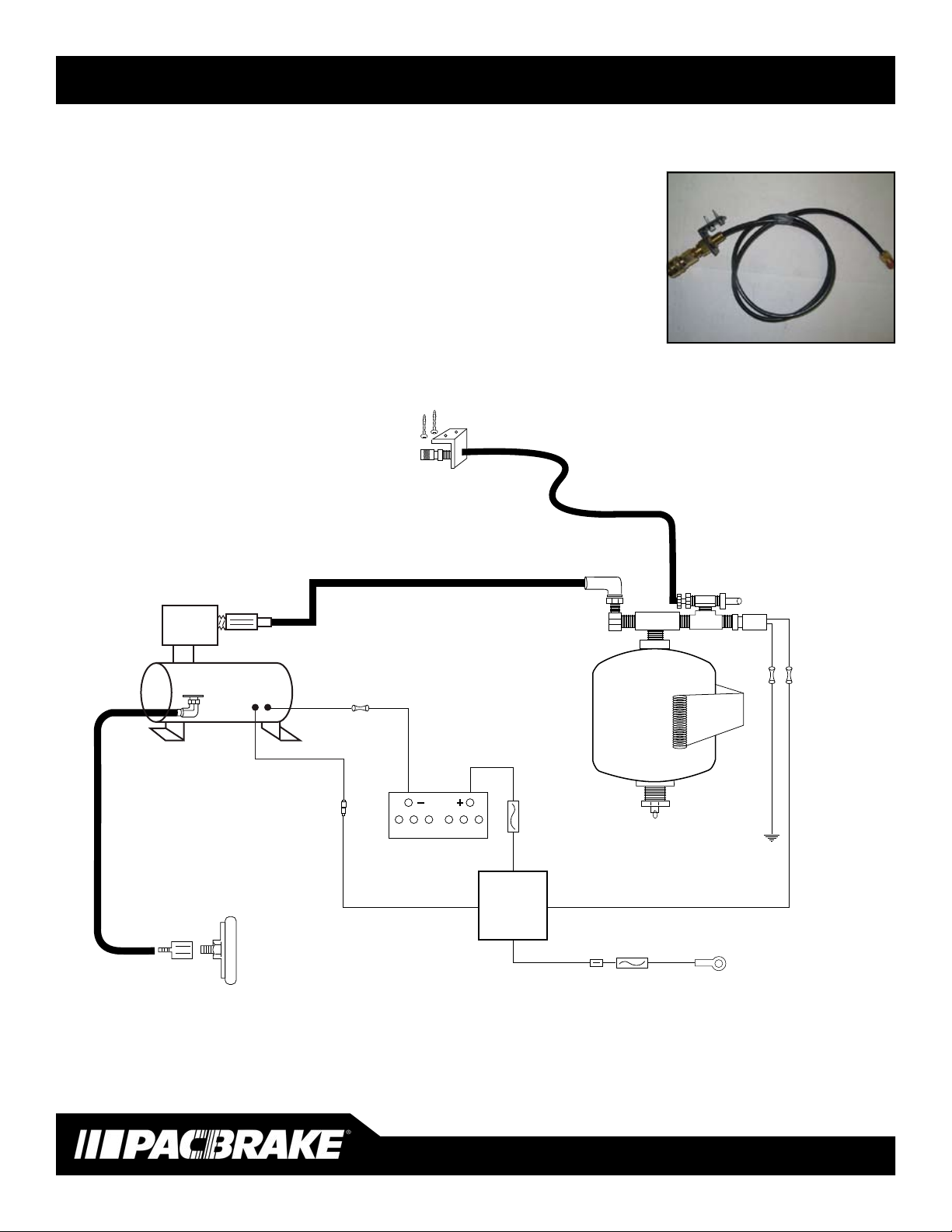
COMPRESSOR AIR INTAKE FILTER
4 Locate the air intake lter housing, barbed tting and 6’ length
of blue nylon hose provided in kit. Choose a location to mount
the lter housing within 6” of the compressor, the housing re-
quires a 1/2” hole for mounting, the location must also provide
clean dry air. Secure the barbed tting to the lter housing,
connect the nylon hose to the barbed tting, install the housing
into the mounting hole. Route the nylon hose to the inlet tting at
the compressor, secure the hose with tie-straps provided.
ELECTRICAL CONNECTIONS
5 Provided in the kit is a pre-wired relay receptacle to make this
part of the installation easy. Find a convenient location close to
the positive battery terminal to mount the relay receptacle. Using
the self tapping screw provided, secure the relay receptacle and
install the relay provided.
6 Locate either one of the two red 12 gage wires of the relay
harness. Cut to length and connect the 30 amp fused link.
Connect the 30 amp fused link to the positive terminal of the
battery. Locate the second red 12 gage wire and route to the
compressor. Cut to length and crimp on the supplied blue butt
connector, then connect to the red compressor wire. Locate the
black wire of the compressor and connect to a good chassis
ground or the negative battery terminal. Heat the
connector’s to provide a water tight seal.
7 Locate the 16 gage red with white strip and the white wire of the
relay harness. Route these two wires into the cab through the
rewall boot. Connect the red with white strip wire to the 5 amp
inline fuse provided, then to a 12 volt ignition power source using
the “T” tap connector provided. Test the ignition power source
with a volt meter prior to attaching the “T” tap. Some ignition
circuits are less than 12 volts which may not be enough to acti-
vate the relay coil. This wire can be connected through an ON/
OFF switch to override the compressor activation, should the
customer prefer this option. (Switch not provided in the kit,
available separately)
Heat the butt connector’s to provide a water tight seal.
4
5
6
7
INSTALLATION MANUAL - INSERT TITLE HERE, L1234
PG 3
INSTALLATION MANUAL - PACBRAKE ONBOARD AIR SYSTEMS, L5856
PG 3
7
8
7 Locate the red 12 gauge wire of the relay harness, route
this wire to the compressor mounting location. Connect to
the red wire at the compressor. Connect the black wire of
the compressor to a good chassis ground. Using the
convoluted loom provided cover the exposed wires and
secure with tie-straps provided.
8 Install the air compressors air intake lter, using the nylon
hose marked air intake connect one end to the barbed tting
below the compressor head. Install the lter housing in the
other end of the nylon hose. Install the lter housing in a dry
clean area below the level of the air intake port to ensure
maximum compressor life.
CONNECTING AIR ACCESSORIES TO THE AIR TANK
9 Do not source air from the bottom port of the air tank. Install
the drain valve provided in the bottom port of the air tank,
periodic draining of the tank will be necessary.
NOTE: The pressure switch included in this kit has a
maximum pressure of 130 PSI and a minimum pressure
of 110 PSI, please ensure your accessories are capable of
this pressure, a regulator maybe necessary for some
accessories. Pacbrake can supply lower pressure switches
upon request. Also, Pacbrake offers dual needle gauge kits
to monitor system pressure. This gauge kit can also be used
to monitor air spring pressure.
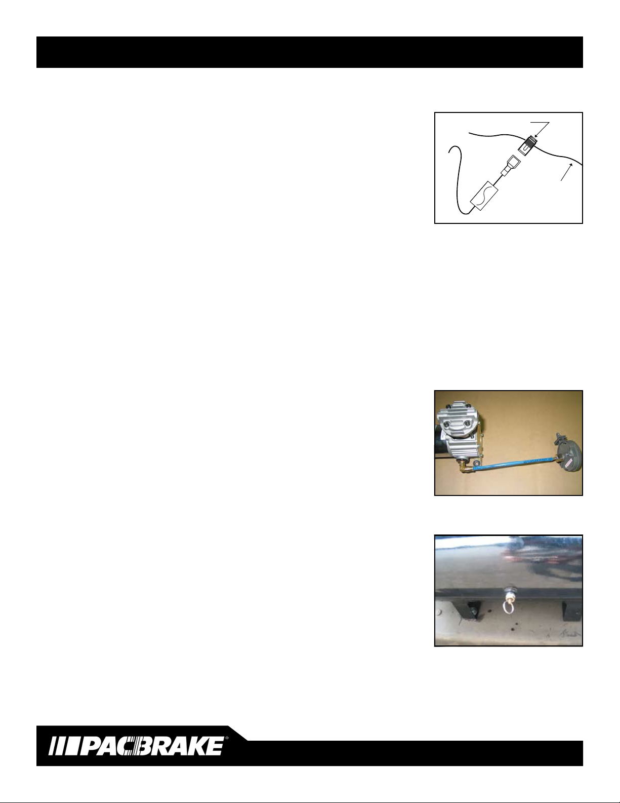
10 Locate the quick disconnect tting provided. Consult with the
vehicle operator for their preference on the mounting
location with easy access. This location should be away
from dirt and moisture which could contaminate the tting.
Using the mounting bracket, self tapping screws, nylon air
line and ttings provided, connect it to the air tank. Use
thread sealant on all ttings installed.
9
10
PG. 3
STEP 5
5Locate the white wire of the relay harness. Connect it to an ignition power
source through the 5 amp inline fuse provided. This wire can be connected
through an ON/OFF switch to override the compressor activation should the
customer prefer this option.
6 Locate the red 12 gauge wire of the relay harness, route this wire to the
compressor mounting location. Connect to the red wire at the compressor.
Connect the black wire of the compressor to a good chassis ground. Using
the convoluted loom provided cover the exposed wires and secure with tie-
straps provided.
7 Install the air compressors air intake lter using the blue nylon hose provided.
Connect one end to the barbed tting below the compressor head. Install the
lter housing in the other end of the nylon hose. Install the lter housing in a
dry clean area below the level of the air intake port to ensure maximum com-
pressor life.
CONNECTING AIR ACCESSORIES TO THE AIR TANK
8Do not source air from the bottom port of the air tank. Install the pressure
relief valve provided in the bottom port of the air tank. Periodic draining of
the tank will be necessary.
NOTE: The pressure switch included in this kit has a maximum pressure
of 130 PSI and a minimum pressure of 110 PSI. Please ensure your
accessories are capable of this pressure - a regulator may be necessary
for some accessories. Pacbrake can supply lower pressure switches upon
request. Also, Pacbrake offers dual needle gauge kits to monitor system
pressure. This gauge kit can also be used to monitor air spring pressure.
STEP 7
STEP 8
INSTALLATION MANUAL - INSERT TITLE HERE, L1234
PG 2
INSTALLATION MANUAL - PACBRAKE ONBOARD AIR SYSTEMS, L5856
PG 2
3
4
5
3 Locate the inline air dryer provided. The dryer should be
mounted vertically between the compressor and the air
tank. The needle valve must be accessible to the operator
for periodic draining. A clamp and fastener is provided to
remote mount the air dryer if desired. Use thread sealant on
all ttings to ensure no air leaks exist.
ELECTRICAL CONNECTIONS
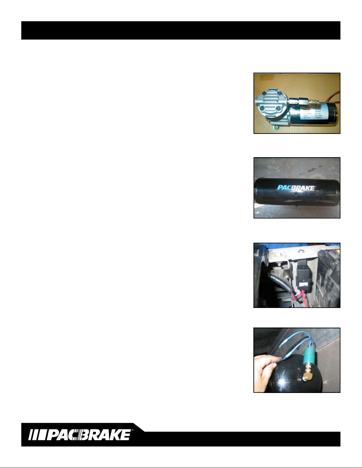
4 Provided in the kit is a pre-wired relay receptacle to make
this part of the installation easy. Find a convenient location
to mount the relay receptacle within 12" of the positive
battery terminal. Using the self tapping screw provided,
secure the relay receptacle and install the relay.
5 Locate the black wire of the relay harness, route it to the
air tank location. Using the ttings provided, install the pres
sure switch into one of the ports in the air tank (DO NOT
INSTALL IN THE BOTTOM PORT) Using the ttings
provided, install the pressure switch in a location for it to
sense air tank pressure. Connect the black wire of the relay
harness to one of the two wires of the pressure switch using
the heat shrink butt connector. Using the loose piece of
black wire and another heat shrink butt connector, connect
to the remaining wire of the pressure switch, heat the
connectors to provide a water tight seal. Then connect the
end with an eye terminal to a good chassis ground.
6 Locate the white wire of the relay harness. Connect it to
an ignition power source through the 5 amp inline fuse
provided. This wire can be connected through an ON/OFF
switch to over-ride the compressor activation should the
customer prefer this option.
If a HP10062 or HP10022 kit is being installed,
a compressor ON/OFF switch is included in these kits
White
5 Amp
Fuse
12v +
Ignition
Switched
14 to 16
gage wire
3M®T-tap connector