Pacbrake PH5 Powerhalt Owner's manual

L6533 •ECN 1-2408
ProgrammingManual

PROGRAMMING MANUAL • PH5 - Mk II AIR INTAKE EMERGENCY SHUT-OFF VALVE
L6533
ECN 1-2408
L6533_Rev1
2
1Operation
•When the controller is unprogrammed, red light will exhibit continuous rapid flash
•When the controller is programmed and in normal operating mode, light will remain off
•When emergency condition arises and engine shutdown is needed, press toggle switch and valve will close
•In overspeed runaway condition, controller will automatically close the valve and shut down the engine
•When the valve is activated, red light will become solidly lit and remain lit until removal of shut-down
signal and a minimum of 15 seconds has elapsed.
•Once shut-down signal is removed and 15 seconds have elapsed, red light will exhibit continuous slow
flash and valve can be reset (continuous slow flash is a reminder that the valve has closed and needs to be
reset)
•Red light will extinguish when engine is restarted and constant RPM is read for 10 seconds (if engine can
be run for 10 seconds, the valve must already be reset - the continuous flash warning will turn itself off)
Use your discretion to reset valve and restart engine after a shut-down event. Do NOT reset the valve until
it is safe to do so. In most cases, it is recommended to wait until the cause is understood and shared with
the necessary safety parties before restarting.
Do NOT activate toggle switch for more than 5 seconds as system may enter Test Mode. Valve will still
close and require manual reset if this occurs.
2Maintenance
To ensure a trouble-free long life of your PowerHalt Shut-Off Valve, a scheduled monthly maintenance procedure
is mandatory:
Seizing due to lack of use is the #1 failure mode of any shut-off valve in the market. As this is a safety
device, activation testing must be employed at a minimum of once per month to ensure system remains
functional and valve is free moving. Daily activations are recommended to ensure proper function of the
system.
•Inspect all fasteners, clamps, and support brackets for tightness and the required torque
•Inspect all wiring / cable runs for corrosion, vibration wear, and loose connections
•Inspect all hoses for cracks, damage, and leaks
•Inspect the controller for damage, dirt, and poor connections
•Activate the valve to ensure it remains functional and free moving

PROGRAMMING MANUAL • PH5 - Mk II AIR INTAKE EMERGENCY SHUT-OFF VALVE
L6533
ECN 1-2408
L6533_Rev1
3
3System Basics
Controller settings are accessed and configured using
the toggle switch and Mode Selection Box.
•Mode Selection Box is located within the speed
sensing harness. See Figure 3-A for summary of
fuse positions.
•Fuse F1 is inserted or removed to access
system programming mode.
Mode Selection Box cap must be re-installed after
use.
Fuse F1 is used only for configuring modes and
is not connected to main system power.
3-A

PROGRAMMING MANUAL • PH5 - Mk II AIR INTAKE EMERGENCY SHUT-OFF VALVE
L6533
ECN 1-2408
L6533_Rev1
4
4Quick Functions
4.1 Manual Trip
Manual Trip closes valve and causes engine (if running) to shut down. To perform Manual Trip:
•Push and release toggle switch. Red light will illuminate to indicate valve has closed.
4.2 Manual Valve Reset
Before resetting valve, ensure indicator light on toggle switch is extinguished. To reset the valve, rotate the RESET
knob clockwise until it latches with the activation solenoid. The indicator line should be parallel with the piping as
shown below in Figure 4-A.
4-A
4.3 Secondary Trip Speed
System can force engine shutdown at 2 different engine speeds. Secondary Trip Speed can be used for protection
of auxiliary equipment powered by Power Take-Off (PTO) system or as anti-theft mechanism when set near idle
speed. To Activate, Program, or Test Secondary Trip Speed,
•Provide 6 to 36 VDC to Pink Wire (Pin 7 on Connector B). This can be done via existing PTO activation
device or via latching switch (not provided).
NOTE: To prevent accidental shut down while enabling/disabling Secondary Trip Speed, a 5 second grace period is
applied when switching to a lower trip speed, to allow for engine speed to reduce. Change is applied immediately
when switching to a higher trip speed.
5Trip Speed Programming Procedure
Set-up is required for emergency shut-off system to function. Controller uses input engine speed and user defined
safety margin to program system trip speed.
Before Programming:
oIF Secondary Trip Speed Input is connected:
Ensure power is NOT supplied to Secondary Trip Speed Input
oIF valve is synchronized with shut-off system on same engine:
Leave all controllers connected to ensure engine shuts down
oIF valve is synchronized with shut off system on secondary engine:
Disconnect secondary controller to prevent accidental shut-down of secondary engine

PROGRAMMING MANUAL • PH5 - Mk II AIR INTAKE EMERGENCY SHUT-OFF VALVE
L6533
ECN 1-2408
L6533_Rev1
5
5.1 For On-Highway Vehicles with Variable Engine Speed
1. Determine desired Trip Speed
•Pacbrake recommends 30% above Rated Engine RPM
2. Insert fuse into F1 in Mode Selection Box. Light will exhibit constant rapid flash interrupted by single pulse*
3. Start engine and raise engine speed to Input Speed –half of desired trip speed –hold constant
4. Push and release switch to shut down engine†and save Input Speed. Light will become solidly lit.
5. When light extinguishes, push and release switch 4 times to set Trip Speed to double Input Speed
6. Light will indicate programming has been saved correctly by flashing 4 times.
7. Remove fuse from F1 in Mode Selection Box to exit Programming Mode. Document Trip Speed for future
reference.
Secondary Trip Speed (If applicable):
Provide power to Secondary Trip Speed Input and repeat above procedure to Program Secondary Trip Speed.
For use as an anti-theft device, it is recommended to set the Trip speed to idle RPM + 10%. In Step 5, press the
switch 1 time to set the Trip Speed to Input Speed +10%. Light will flash 1 time as confirmation in Step 6.
5.2 For Stationary Engines with Constant Operating Speed
1. Determine desired Trip Speed
2. Insert fuse into F1 in Mode Selection Box. Light will exhibit constant rapid flash interrupted by single pulse*
3. Start engine and allow it to run at constant operating speed
4. Push and release switch to shut down engine†and save Input Speed. Light will become solidly lit
5. When light extinguishes, choose desired Overspeed Margin from below to set your Trip Speed:
•Push & release switch 1 time –Operating Speed + 10%
•Push & release switch 2 times –Operating Speed + 20%
•Push & release switch 3 times –Operating Speed + 30%
6. Light will indicate programming has been saved correctly by flashing the same number of times the switch was
pressed
7. Remove fuse from F1 on Mode Selection Box to exit Programming Mode. Document Trip Speed for future
reference.
Secondary Trip Speed (If applicable):
Provide power to Secondary Trip Speed Input and repeat above procedure to program Secondary Trip Speed
NOTE: Table below demonstrates a simple example of programming your system.
Input Speed
Switch Presses
Overspeed Margin
Trip Speed
Margin
RPM
1000
1
+ 10%
+ 100
1100
1000
2
+ 20%
+ 200
1200
1000
3
+ 30%
+ 300
1300
1000
4
Double
+ 1000
2000
*Light will exhibit ‘double pulse’ if Secondary Trip Speed is active
†Automatic overspeed protection is disabled during Programming Mode therefore engine shut down is forced on switch push as precautionary measure to
guard against possible emergency situation.

PROGRAMMING MANUAL • PH5 - Mk II AIR INTAKE EMERGENCY SHUT-OFF VALVE
L6533
ECN 1-2408
L6533_Rev1
6
6Trip Speed Test Procedure
After following Trip Speed Programming Procedure, system must be tested to ensure Trip Speed was programmed
correctly. Entering TEST Mode causes system to trip at ‘Input Speed’ from Programming Procedure –raising engine
speed to actual ‘Trip Speed’ is unsafe and unnecessary.
Before Testing:
oIF Secondary Trip Speed Input is connected and Secondary Trip Speed has been Programmed:
Ensure power is NOT supplied Secondary Trip Speed Input before beginning Test Procedure
oIF valve is synchronized with shut-off system on same engine:
Leave all controllers connected to ensure engine shuts down
oIF valve is synchronized with shut off system on secondary engine:
Disconnect secondary controller to prevent accidental shut-down of secondary engine
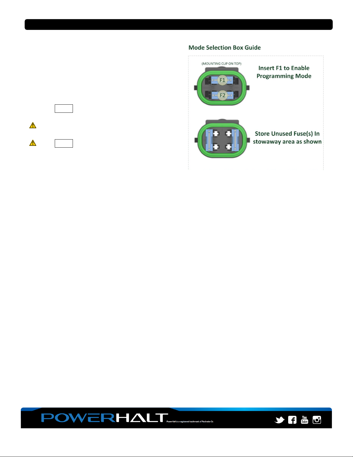
1. Ensure fuse is removed from F1 in Mode Selection Box
2. With engine off, push switch to close valve and hold switch for 5 seconds until light begins flashing rapidly
3. Release switch to re-open valve. Light will exhibit continuous rapid flash interrupted by single pulse*
4. Start engine and slowly raise engine speed to ‘Input Speed’ as previously recorded
5. Valve will close and red light will illuminate until 0 RPM is detected and 15 seconds have elapsed. When
red light extinguishes valve will be safe to re-open manually.
6. If valve did not close when expected, trip speed may not be correctly programmed. Confirm installation
and re-follow Trip Speed Programming Procedure on previous page.
Secondary Trip Speed (If applicable):
•Provide power to Secondary Trip Speed Input and repeat above procedure to test Secondary Trip Speed
*Light will exhibit ‘double pulse’ if Secondary Trip Speed is active
Table of contents
Other Pacbrake Control Unit manuals